
Subscribe to Our Youtube Channel
Related Manuals for Intellijel Shifty


Summary of Contents for Intellijel Shifty
- Page 1 Shifty Manual v 1.00 Shifty Voice Allocator / Hocketing Controller / Analog Shift Register...
- Page 2 Shifty Manual v 1.00 Table of Contents Table of Contents Overview Features Installation Before Your Start Installing Your Module Front Panel Controls Inputs and Outputs Instructions Voice Allocation Mode Shift Register Mode Track & Hold / Sample & Hold Sampling Delay Compensation...
- Page 3 Allocation Mode . Another term for this is h ocketing Shifty can also function as a digital emulation of an A nalog Shift Register . An Analog Shift Register is essentially a little 4-slot voltage recorder and sequencer. When the first clock is received, Shifty passes the corresponding CV value to the first output.
-
Page 4: Installation
Shifty Manual v 1.00 Installation Intellijel Eurorack modules are designed to be used with a Eurorack-compatible case and power supply. Before Your Start Before installing a new module in your case you must ensure your case’s power supply has sufficient available capacity to power the module: ●... - Page 5 Eurorack case. Ensure the red stripe on the cable lines up with the -12V pins on the bus board. On Intellijel power supplies the pins are labelled with the label “-12V” and a thick white stripe: If you are using another manufacturer’s power supply, check their documentation for instructions.
- Page 6 Shifty Manual v 1.00 Once connected, the cabling between the module and power supply should resemble the picture below: Before reconnecting power and turning on your modular system, double check that the ribbon cable is fully seated on both ends and that all the pins are correctly aligned. If the pins are misaligned in any direction or the ribbon is backwards you can cause damage to your module, power supply, or other modules.
-
Page 7: Front Panel
Shifty Manual v 1.00 Front Panel Page 6... -
Page 8: Inputs And Outputs
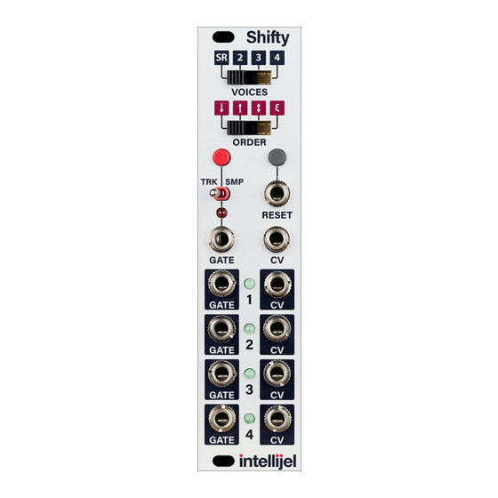
Shifty Manual v 1.00 Controls 1. VOICES - This switch selects the number of voices, or outputs, used by the module. In the first setting, SR, it causes the module to operate as a shift register. 2. ORDER - This switch selects in which order the input is assigned to the outputs. The options are: ascending, descending, ping-pong, and random. - Page 9 4 different oscillators and envelope generators. Simply connect the PITCH and GATE out to the CV and GATE ins of the Shifty, and then connect each pair of CV and GATE outputs to an oscillator pitch input an envelope trigger. Each GATE and CV output pair is considered a “voice”.
- Page 10 Voice Allocation Mode is the primary mode of Shifty which is enabled whenever VOICES is set to 2, 3, or 4. In this mode Shifty will play one of the four voices each time it receives a gate. The order in which the voices are played is determined by the ORDER switch. There are four ORDER settings: ...
-
Page 11: Shift Register Mode
Shifty Manual v 1.00 Shift Register Mode Shift Register mode is a digital emulation of an Analog Shift Register (ASR). It is enabled when the VOICES switch is set to the leftmost position ( S R ) . This mode works differently from the other three VOICE settings: Instead of replacing one of the CV outputs, the other voices are “shifted”... - Page 12 In the case of Shifty if the module is being used in track & hold mode mode this is rarely a problem because this behaviour will simply result in a short and usually inaudible pitch glide at the beginning of the note.
- Page 13 Shifty Manual v 1.00 Calibration Shifty comes calibrated out of the factory and usually there should be no need to perform calibration. 1. Hold the RESET button while powering on your modular system. Shifty will start up in calibration mode.
-
Page 14: Technical Specifications
Shifty Manual v 1.00 Technical Specifications Width 6 hp Maximum Depth 44 mm Current Draw 52 mA @ +12V 5 mA @ -12V Page 13...
Need help?
Do you have a question about the Shifty and is the answer not in the manual?
Questions and answers