
Related Manuals for Intellijel Atlantix


Summary of Contents for Intellijel Atlantix
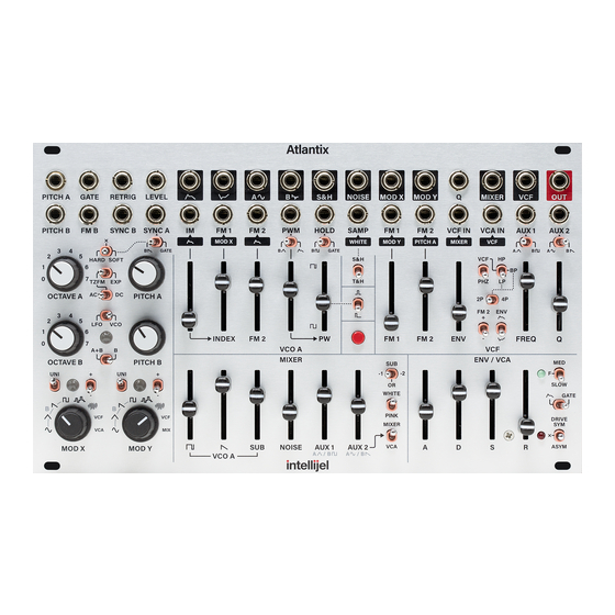
- Page 1 Atlantix Analog Dual-Oscillator Synthesizer Voice & Optional Expander Manual (English) Revision: 2024.06.20...
-
Page 2: Table Of Contents
VCF Jacks ENVELOPE / VCA ENVELOPE / VCA Controls ENVELOPE / VCA Jacks MODS MOD Controls MOD Jacks ATLX EXPANDER MODULE DETAILS DETAILS: Understanding FM Exponential vs. Linear FM Thru-Zero FM (TZFM) DETAILS: Understanding OSC Sync TECHNICAL SPECIFICATIONS Atlantix Manual... -
Page 3: Compliance
(2) this device must accept any interference received, including interference that may cause undesired operation. Changes or modifications not expressly approved by Intellijel Designs, Inc. could void the user’s authority to operate the equipment. Any digital equipment has been tested and found to comply with the limits for a Class A digital device, pursuant to part 15 of the FCC Rules. -
Page 4: Installation
INSTALLATION Intellijel Eurorack modules are designed to be used with a Eurorack-compatible case and power supply. We recommend you use Intellijel cases and power supplies. Before installing a new module in your case, make sure your power supply has a free power header and sufficient available capacity to power the module: ●... -
Page 5: Installing Your Module
Eurorack case. Ensure the red stripe on the cable lines up with the -12V pins on the bus board. On Intellijel power supplies the pins are labeled with “-12V” and/or a thick white stripe, while others have shrouded headers to prevent accidental reversal. -
Page 6: Front Panel
Though sonically rich on its own, Atlantix features 32 individual patch points to enable advanced configurations and to integrate with other eurorack modules. Another 16 patch points are available on the optional ATLX expander module, discussed later. -
Page 7: Vco A
VCO A SECTION 1 VCO A is Atlantix’ primary oscillator and is capable of a wide variety of analog timbres via its extensive sync, FM (frequency modulation) and PWM (pulse width modulation) features. VCO A Controls [1.1] OCTAVE A selector - This 8-position selector knob sets the coarse tuning of VCO A. Each clockwise rotation shifts the tuning up by one octave. - Page 8 (a square wave). With the slider at the top, the resulting pulse has approximately a 95% duty cycle, resulting in a thinner sounding pulse wave. You can reach 100% (silencing the oscillator) using the PWM IN [1.F] control. Atlantix Manual...
- Page 9 ● SOFT (right) – This produces a ‘softer’ sync sound. It flips the VCO A waveform each time the oscillator patched into SYNC A [1.B] crosses zero in the positive direction. Waveforms with sharp edges (like square or saw) work best with SOFT sync. Atlantix Manual...
-
Page 10: Vco A Jacks
PWM IN - This input has a range of +/- 5 V, and is used to modulate VCO A’s pulse width. The amount of PWM is governed by the PWM [1.6] slider, and the resulting voltage is summed with the current Pulse Width (as set with the PW [1.8] amount slider), and together Atlantix Manual... - Page 11 100%, thus silencing the PULSE output, allowing for pulsing/rhythmic pitches. DEFAULT ROUTING: If nothing is patched into this jack, then the PWM SOURCE switch [1.7] selects the input. [1.G] VCO A SINE out - Dedicated Sine wave output for VCO A. Atlantix Manual...
-
Page 12: Vco B
VCO B SECTION 2 VCO B is Atlantix’ secondary oscillator — useful as either a secondary audio rate source or as a modulation source capable of running at either audio or LFO rates. VCO B Controls [2.1] OCTAVE B selector - This 8-position selector knob sets the coarse tuning of VCO B. Each clockwise rotation shifts the tuning up by one octave. -
Page 13: Vco B Jacks
SYNC B IN - VCO B will sync to the waveform received at this input, using hard sync. For more information about oscillator sync (and the meaning of “hard” sync), see DETAILS: Understanding OSC Sync , later in this manual. [2.D] VCO B SPIKE out - Dedicated Spike wave output for VCO B. Atlantix Manual... -
Page 14: Mixer
MIXER [3.C] output, which is also normalled to the VCF input. The SUB OSC is derived from the VCO A pulse wave, with its pitch and shape determined by the SUB TYPE [3.9] selector switch. Atlantix Manual... - Page 15 ● WHITE : White noise is the brightest sounding, since it contains equal energy at every frequency. This gives more emphasis to the higher frequencies. ● PINK : Pink noise is ‘darker’ than white, since it contains equal power per octave — giving more emphasis to the lower frequencies. Atlantix Manual...
-
Page 16: Mixer Jacks
MIXER Jacks [3.A] AUX 1 IN - Use this jack to patch an external signal into Atlantix (or to self patch a signal from within Atlantix). The signal is attenuated in Atlantix’ MIXER section and injected into the input of the MIXER. -
Page 17: Vcf
FM 2 voltage is inverted, allowing for negative modulation. DEFAULT ROUTING: If nothing is patched into the FM 2 IN [4.B] jack, then the PITCH of VCO A is used as the FM 2 source, allowing the filter to track pitch. Atlantix Manual... - Page 18 [4.3] ENV Amount slider - This controls how much Atlantix’ ENVELOPE modulates the filter’s frequency. When the slider is at the top, maximum Frequency Modulation occurs. When the slider is at the bottom, no FM occurs. The ENV Polarity [4.10] switch determines whether the ENVELOPE is inverted, allowing for negative modulation.
- Page 19 4P/2P [4.7] switch. ● HP - Highpass filter. Frequencies lower than the modulated cutoff FREQ [4.4] are attenuated. The 4P/2P [4.7] switch has no effect on the HP filter, which always operates as 4-pole filter. Atlantix Manual...
- Page 20 In the up position, the incoming envelope is not inverted, meaning positive voltages increase the filter frequency and negative voltages decrease it. In the down position, the incoming envelope is inverted, such that positive voltages decrease the filter frequency in a negative voltages increase it. Atlantix Manual...
-
Page 21: Vcf Jacks
[4.9] switch. DEFAULT ROUTING: If nothing is patched into the FM 2 input jack, then FM 2 tracks Atlantix’ pitch input. [4.C] VCF IN - Audio Input to the filter. DEFAULT ROUTING: If nothing is patched into the VCF IN jack, then the output of MIXER feeds the VCF. -
Page 22: Envelope / Vca
ENV Polarity [4.10] switch. It’s also available in both regular [5.D] and inverted [5.E] outputs on the panel. The VCA is a unity-gain linear voltage controlled amplifier that controls the amplitude of any signal passing through it. Atlantix Manual... -
Page 23: Envelope / Vca Controls
Approximate maximum times are: ~19 to 21 s D/R : ~70 to 75 s The switch’s associated LED indicates the voltage of the envelope as it plays through. The brighter the LED, the higher the voltage. Atlantix Manual... - Page 24 [5.6] ENV/GATE switch - Selects whether the VCA (loudness) is controlled by Atlantix’ ADSR envelope or if it’s simply gated (like an organ) by the GATE [5.A] input or MANUAL GATE [5.8] button. Specifically: ● ADSR : In this position, the VCA uses the ADSR envelope settings to control the loudness of a note over time.
-
Page 25: Envelope / Vca Jacks
MIXER section is set to the VCA position, then the signal present at the AUX 2 IN [3.B] jack is attenuated by the AUX 2 amount [3.6] slider and summed with the VCA IN signal. [5.G] OUT - Atlantix’ audio output (maximum of 10V peak-to-peak). Atlantix Manual... -
Page 26: Mods
MODS SECTION 7 Atlantix features a wealth of sophisticated and diverse modulation options for self-patching and/or use with external modules. Besides the built-in sample & hold circuitry, there are two modulation source selectors ( X and Y ), each with eight options from which to choose, and the ability to switch between unipolar &... - Page 27 ● S&H (up): The circuit operates as a traditional sample & hold — sampling the S&H SAMP [6.B] voltage at the rising edge of a signal patched into the S&H HOLD [6.A] input, and holding that sampled voltage steady until the next rising Atlantix Manual...
-
Page 28: Mod Jacks
This creates a new static voltage every “pulse,” which Atlantix sends out the S&H [6.C] OUT jack. ● T&H (down), The circuit samples the S&H SAMP [6.B] voltage at the falling edge of a signal patched into the S&H HOLD [6.A]... -
Page 29: Atlx Expander Module
The optional ATLX expander module provides numerous additional outputs plus two additional inputs for the built-in ring modulator. It connects to the Atlantix module using the included 20-pin ribbon cable. The ATLX expander is passive and does not need a power connection. - Page 30 B SIN out : Dedicated Osc B Sine wave output. [X.N] B TRI out : Dedicated Osc B Triangle wave output. [X.O] B SAW out : Dedicated Osc B Sawtooth wave output. [X.P] B SQUARE out : Dedicated Osc B Square wave output. Atlantix Manual...
-
Page 31: Details
(which is called FM INDEX). Exponential vs. Linear FM In general, there are two distinct types of FM, both of which are supported by Atlantix: ● EXPONENTIAL FM is the type found in many vintage analog mono synths of the 1970’s. When you change the frequency of the modulator, you change the perceived fundamental pitch that emerges from the carrier oscillator. -
Page 32: Thru-Zero Fm (Tzfm)
TZFM oscillators can produce “deeper” and “richer” timbres than standard, positive-only FM’d oscillators, and Atlantix supports two types of TZFM: DC (which is the deepest variant — ideal for slower modulators, such as LFOs); and AC (not as deep, but more accurate at tracking pitch variations). -
Page 33: Details: Understanding Osc Sync
“the sync sound” in classic synths. ● SOFT SYNC – This is an alternate VCO sync method. Atlantix uses a form of soft sync known as “flip” sync, which reverses the direction of the triangle core wave, rather than resetting it. -
Page 34: Technical Specifications
TECHNICAL SPECIFICATIONS Width Atlantix: 42 hp ATLX expander: 6 hp Maximum Depth 25 mm Current Draw 140 mA @ +12V (Atlantix) 138 mA @ -12V Atlantix Manual...
Need help?
Do you have a question about the Atlantix and is the answer not in the manual?
Questions and answers