
Subscribe to Our Youtube Channel
Related Manuals for Intellijel Sealegs


Summary of Contents for Intellijel Sealegs
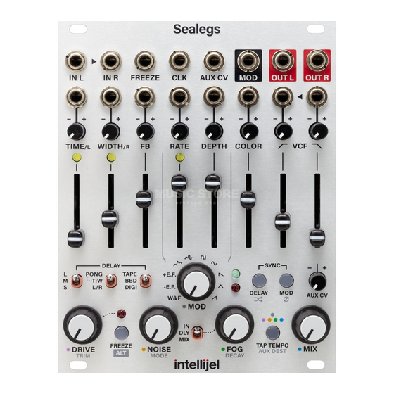
- Page 1 Sealegs Multi-Modeled Stereo Character Delay with Reverb Manual (English) Revision: 2023.08.17...
-
Page 2: Table Of Contents
Delay Function Controls Delay Function Jacks FRONT PANEL : MOD FUNCTIONS Character Function Controls Character Function Jacks FRONT PANEL : CHARACTER FUNCTIONS Character Function Controls Filter Function Jacks Filter Explanation FIRMWARE UPDATES Current Firmware Display Firmware Versions TECHNICAL SPECIFICATIONS Sealegs Manual... -
Page 3: Compliance
(2) this device must accept any interference received, including interference that may cause undesired operation. Changes or modifications not expressly approved by Intellijel Designs, Inc. could void the user’s authority to operate the equipment. Any digital equipment has been tested and found to comply with the limits for a Class A digital device, pursuant to part 15 of the FCC Rules. -
Page 4: Installation
INSTALLATION Intellijel Eurorack modules are designed to be used with a Eurorack-compatible case and power supply. We recommend you use Intellijel cases and power supplies. Before installing a new module in your case, you must ensure your power supply has a free power header and sufficient available capacity to power the module: ●... -
Page 5: Installing Your Module
Eurorack case. Ensure the red stripe on the cable lines up with the -12V pins on the bus board. On Intellijel power supplies the pins are labelled with “-12V” and/or a thick white stripe,... -
Page 6: Overview
OVERVIEW Our design goal for Sealegs was to create the warmest, most musical and organic delay module possible — something that would sweeten and enhance any audio one chose to feed into it. As such, great care has gone into modeling the most characterful sonic characteristics of three different types of delays circuits (tape;... -
Page 7: Front Panel Overview
This section consists of a dedicated COLOR parameter that’s uniquely tuned to each of Sealegs’ three delay models (TAPE, BBD and DIGI), plus Low Pass and High Pass filters, which sit inside the feedback loop (unless frozen), enabling frequency response characteristics that change over time. -
Page 8: Front Panel : Global Functions
DRIVE LED, which (in STANDARD operation) turns red to indicate overdrive is engaged. NOTE: Sealegs taps its DRY signal after the overdrive circuit, so you can also use Sealegs as a drive-only module with the MIX knob turned fully counterclockwise . - Page 9 , the delay buffer is frozen (no additional data is written to it) and loops continuously until unfrozen. NOTE 1: When Sealegs is frozen, the VCF circuit moves outside the feedback loop, where it affects only the delay’s output signal.
- Page 10 ● MIX (bottom) : Fog is positioned at the very end of the signal chain, post MIX — meaning it affects both the wet and the dry signals. The following illustration depicts the Fog location with the STEREO CONFIG [18] switch in the middle position, and the CROSS FB feature turned off. Sealegs Manual...
- Page 11 FOG a depth set by the AUX CV attenuverter [10] Blue (5x flashes): A signal patched into the AUX CV IN jack controls the MIX at a depth set by the AUX CV attenuverter [10] Sealegs Manual...
- Page 12 Turning the knob counterclockwise from the noon position inverts the incoming CV (positive voltages become negative, and vice-versa), with the voltage level steadily increasing until the full (but inverted) range is reached when the knob is fully counter-clockwise. Sealegs Manual...
-
Page 13: Global I/O Jacks
If you’re processing a mono signal, then use this jack as the mono input, and leave IN R unpatched. IN R : Right channel input for the stereo signal you want processed through Sealegs. If nothing is patched into this jack, then the mono signal that’s patched into IN L normalled to it. -
Page 14: Front Panel : Delay Functions
L/R , the TIME slider directly sets the delay time for whichever delay is routed to the LEFT, while WIDTH [13] slider directly sets the delay time for whichever delay is routed to the RIGHT. Sealegs Manual... - Page 15 50ms create chorus or doubling effect, and delays longer than around 50-60ms create discrete echoes, patterns or (at longer times) looping effects. The feedback slider goes up to 160%, meaning it’s possible to create runaway feedback effects, where the volume increases over time. Sealegs Manual...
- Page 16 L/R ). WIDTH [13] slider’s if the STEREO CONFIG [18] The range options are different depending on whether or not the DELAY TIME is being sync’d to a clock, as shown in the illustration below. Sealegs Manual...
- Page 17 (based on an incoming CLOCK of a sixteenth note). This results in a range of delay times that repeat from 4 times the rate of the incoming clock (in other words, faster delays) up to the clock rate. Sealegs Manual...
- Page 18 [18] STEREO CONFIG switch : This switch positions Sealegs’ dual delay lines into one of three different stereo configurations: ● PONG (top) : The Left and Right inputs are summed to mono and sent into the delay loop, which positions the two delays in series. The first delay time is set by the...
- Page 19 (Post Delay) position, and the FB CROSS setting in its default (off) state. FB CROSS is enabled, then crossing the feedback sends the output of the Right delay back into the Left input, and vice versa, creating the following routing: Sealegs Manual...
- Page 20 (Post Delay) position, and the FB CROSS setting in its default (off) state. FB CROSS is enabled, then crossing the feedback sends the output of the Right delay back into the Left input, and vice versa, creating the following routing: Sealegs Manual...
-
Page 21: Delay Function Jacks
[19] MODEL switch : Sets the delay type used by Sealegs: ● TAPE (top) : Replicates the characteristics of tape-based delays, with the additional COLOR [26] slider introducing additional tape-related degradations. ● BBD (mid) : Replicates the characteristics of bucket brigade style delays, with the... -
Page 22: Front Panel : Mod Functions
FRONT PANEL : MOD FUNCTIONS Sealegs features a versatile set of controls for generating complex modulations and additional sonic degradation. By default, the MOD Wave modulates Sealegs’ own TIME [11] at a rate set by the MOD RATE [20] slider, and at an amount set by the... - Page 23 MOD DEPTH slider : Sets the extent to which the selected MOD [24] waveform modulates Sealegs’ Delay Time. NOTE : This slider affects only the depth of internal modulation. It does not affect the amplitude of the modulation sent out the MOD jack.
- Page 24 MOD OUT jack allows you to modulate external modules (or even other Sealegs parameters via self patching). This knob has both a “standard” and an ALT function. ● STANDARD : Turning the MOD knob from fully counterclockwise to fully clockwise, moves through the following wave shapes: The first three waveforms (W&F, EF- and EF+) are...
- Page 25 MOD knob clockwise (unless you hold down the button while turning it, in which case it will jump to the RAMP wave, without morphing into it). RAMP : Creates a cycling waveform that ramps up from -10V to +10V, then immediately resets back to -10V. Sealegs Manual...
-
Page 26: Character Function Jacks
MOD DEPTH CV Attenuverter [23] MOD OUT : Output of the control voltage (CV) generated by Sealegs’ MOD WAVE. The MOD WAVE always affects the internal DELAY TIMES at an amount set by the MOD DEPTH... -
Page 27: Front Panel : Character Functions
But, since the cutoff frequencies of both filters can be modulated, all sorts of harmonic variation can be applied to a feedback loop. If Sealegs is currently in FREEZE mode, then the filter is moved outside the... - Page 28 LOWPASS FREQ. Turning the knob counterclockwise from the noon position inverts the incoming CV (positive voltages become negative, and vice-versa), with the voltage level steadily increasing until the full (but inverted) range is reached when the knob is fully counter-clockwise. Sealegs Manual...
-
Page 29: Filter Function Jacks
Positive voltages increase the cutoff frequency above the value currently set with the LOWPASS FREQ [30] slider; negative voltages decrease it. You can limit (or even invert) the incoming voltage using the LOWPASS FREQ CV Attenuverter [31] Sealegs Manual... -
Page 30: Filter Explanation
Consequently, positioning the HIGHPASS FREQ [28] slider above the LOWPASS FREQ [30] slider will not result in a total cessation of sound, but rather an attenuated reduction of overall level, centered around the midway point between the two sliders. Sealegs Manual... -
Page 31: Firmware Updates
Current Firmware Display For the first 3 seconds after Sealegs turns on, the colored panel buttons indicate the currently installed firmware. Specifically, firmware versions use a w.x.y.z format, where different front panel buttons indicate the values of W, X, Y, and Z. Specifically: W .x.y.z (major) = FREEZE button... -
Page 32: Firmware Versions
Firmware Versions 1.0 (August, 2023) ● Initial release TECHNICAL SPECIFICATIONS Width 20 hp Maximum Depth 29 mm Current Draw 116 mA @ +12V 10 mA @ -12V Sealegs Manual...
Need help?
Do you have a question about the Sealegs and is the answer not in the manual?
Questions and answers