
Related Manuals for Intellijel Planar2


Summary of Contents for Intellijel Planar2
- Page 1 Planar Multi-Axis Vector Controller & Recorder Manual (English) Firmware Version: 1.2 | Revision: 2021.10.04...
-
Page 2: Table Of Contents
TABLE OF CONTENTS COMPLIANCE INSTALLATION Installing Your Module OVERVIEW Features A Cornucopia of Control FRONT PANEL Inputs Outputs Controls X/Y CONTROL GATE GENERATOR QUAD FUNCTIONS Manual Quad Crossfader Crossfading With Fewer Than Four Inputs Quad Panner Quad Router Four Quadrant CV Generator CV GESTURE RECORDER Record &... - Page 3 USING A Gx OR Qx GATE EXPANDER Installing the Gx/Qx Using the Gx/Qx CALIBRATION Automatic Calibration Manual Calibration Calibration Testing FIRMWARE UPDATES TECHNICAL SPECIFICATIONS Planar Manual...
-
Page 4: Compliance
(2) this device must accept any interference received, including interference that may cause undesired operation. Changes or modifications not expressly approved by Intellijel Designs, Inc. could void the user’s authority to operate the equipment. Any digital equipment has been tested and found to comply with the limits for a Class A digital device, pursuant to part 15 of the FCC Rules. -
Page 5: Installation
INSTALLATION Intellijel Eurorack modules are designed to be used with a Eurorack-compatible case and power supply. We recommend you use Intellijel cases and power supplies. Before installing a new module in your case, you must ensure your power supply has a free power header and sufficient available capacity to power the module: ●... -
Page 6: Installing Your Module
Installing Your Module When installing or removing a module from your case always turn off the power to the case and disconnect the power cable. Failure to do so may result in serious injury or equipment damage. Ensure the 10-pin connector on the power cable is connected correctly to the module before proceeding. -
Page 7: Overview
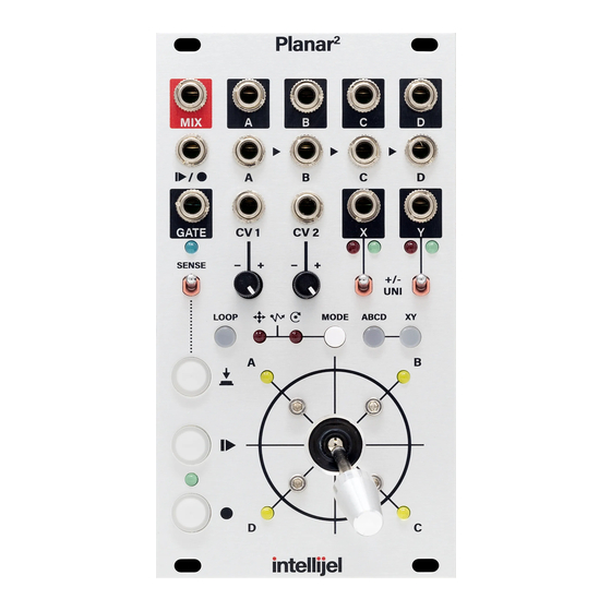
OVERVIEW With its smoothly responsive precision joystick, Planar facilitates hands-on vector control of two entirely independent sets of outputs (quadrants A-D, and axis X/Y), plus the ability to capture and playback your gestures. Recording your joystick movements enables the creation of organic and complex envelopes, wild and wobbly LFOs, or extended sonic evolutions. -
Page 8: A Cornucopia Of Control
CV to modify the four quadrant outputs (A, B, C, and D) or the dual-axis X/Y outputs. ● Using a Gx or Qx gate expander module - You can connect an optional Intellijel Gx or Qx gate expander module to the Planar — increasing its utility as a programmable gate generator, or to trigger gate events that correspond to directional changes in joystick position. -
Page 9: Front Panel
FRONT PANEL Planar Manual... -
Page 10: Inputs
Inputs In the previous illustration, the green numerical labels indicate Planar inputs. [1] A IN, B IN, C IN, D IN Each of these jacks accepts an input signal, which the Planar routes through an internal VCA, attenuates, and passes on to the correspondingly lettered output jacks , or sums to the MIX output jack. -
Page 11: Outputs
Outputs In the previous illustration, the numerical labels indicate Planar outputs. [5] A OUT, B OUT, C OUT, D OUT These are the direct outputs of the four internal VCAs, through which Inputs A-D are routed. Output levels may be adjusted and/or automated by any of the following means: ●... -
Page 12: Controls
[8] X OUT Outputs a voltage corresponding to the X-axis on Planar . The X-axis value is controlled by a number of factors, including: position of joystick along the X-axis; recorded value of joystick; CV input, CV mode; and state of the XY button [B]. - Page 13 [B] XY button This button controls the various ways in which the joystick, internal recording and CV inputs all affect the X and Y control voltage outputs. The button has three states: ● LIT = CV IN + (JOYSTICK or RECORDING) When the XY button is lit, the joystick sends its position to the X and Y outs.
- Page 14 [C] ABCD button This button behaves exactly the same as the XY button , described above, only it governs how outputs A , B, C, D and MIX are affected by the joystick, a recording, or the CV inputs. NOTE: As with the XY button , Planar checks the status of the ABCD button approximately every 30 seconds, and if it’s changed, writes the new state to memory.
- Page 15 [I] MODE button & indicator LEDs Press the MODE button to cycle through the three ways in which the CV 1 and CV 2 inputs may influence the level of outputs A-D , their relative levels in the MIX OUT [6], or the and Y...
- Page 16 [K] GATE out indicator LED This indicator lights blue whenever a high gate signal is being sent out Planar [L] Manual Gate button Pressing this button sends a gate signal to the GATE OUT jack. The gate signal remains high for as long as the Manual Gate button is held down.
- Page 17 This allows you to make small edits to existing recordings or to evolve a recording over the course of a song. NOTE: To erase a recording entirely, press and hold the PLAY button for over one second. For more information about recording, see CV Gesture Recorder , later in this manual.
- Page 18 [P] LOOP Button This button controls whether or not your joystick recording will loop and, if so, how it loops in the presence of external triggers. The button has three states: ● UNLIT : If the LOOP button is unlit, then your recorded joystick movements will play only once when you press the PLAY button to start playback.
- Page 19 Accessing these three states involves either quickly-pressing the LOOP button or pressing-and-holding it for 1 second. Specifically: ● Quick-press the LOOP button to toggle it ‘on’ and ‘off’. If the LOOP button is on (either steadily lit or flashing), quick-pressing the button turns it off.
-
Page 20: X/Y Control
X/Y CONTROL In its most simple operating scenario, the Planar joystick acts as a two-axis CV generator. Moving the joystick along the X-axis generates control voltages from the X OUT jack, while moving the joystick along the Y-axis generates control voltages from the Y OUT jack. - Page 21 modulating. But if the joystick is left of the center point (X) or below it (Y), it will subtract from the baseline value of the parameter you’re modulating. So in this example, setting X’s polarity to +/- would cause the joystick to increase the Polaris’ Cutoff frequency whenever the joystick is right of center, and it would decrease the Polaris’...
-
Page 22: Gate Generator
GATE GENERATOR Tangentially related to the joystick is the gate function. Specifically if the SENSE switch is turned on (up position) and the joystick is in motion, then Planar sends a +5V gate signal to its GATE OUT jack for as long as you’re moving the joystick. In addition, you may use the Manual Gate button to create gates manually. - Page 23 To generate gates without using the joystick: You can always use the Manual Gate button to generate a gate regardless of the SENSE switch position. To do so: Connect the GATE OUT jack to a gate input on some module you wish to control. Press the Manual Gate button to generate a gate.
-
Page 24: Quad Functions
QUAD FUNCTIONS In this section, you’ll learn how to use Planar as a quad crossfader, panner, processing router, and four-quadrant CV generator. You’ll also learn how to automate these functions using the CV 1 and CV 2 inputs. Manual Quad Crossfader Use this technique to dynamically mix and crossfade between as many as four inputs. -
Page 25: Crossfading With Fewer Than Four Inputs
Crossfading With Fewer Than Four Inputs Planar normals its four inputs in a cascading fashion. That is, if if nothing is plugged into IN B , then it’s normalled to IN A ; If nothing is plugged into IN C , then it’s normalled to IN B , and so on down the chain. - Page 26 To create a dual-channel crossfade: Plug one audio source into IN A and the other into IN C . Plug the MIX output into your sound system. If the ABCD button isn’t already lit, press it to turn on the ABCD outputs and light the button (either the flashing or steady lit states will do).
-
Page 27: Quad Panner
Quad Panner If you’re using your eurorack system in a surround sound or quadraphonic system, you can use Planar to move any signal left, right, forward or backward throughout the quadraphonic field. Specifically: Plug an audio source into IN A . Connect OUTS A-D to the four channels of your quadraphonic sound system. -
Page 28: Four Quadrant Cv Generator
Four Quadrant CV Generator With nothing connected to inputs A-D , you can use outputs A-D as individual control voltage sources. Unlike X/Y control, outputs A-D are strictly unipolar (0V to +10V). To use the joystick to generate control voltages from outputs A, B, C and D: Connect the A OUT jack to a CV input on some module you wish to control. -
Page 29: Cv Gesture Recorder
CV GESTURE RECORDER This section discusses how to record your joystick motions (including gates), and play them back either as 1-shot complex envelope-like functions or as looped, LFO-like functions. You can synchronize a recording’s start time and length to an external trigger for metric rigidity, or you can record a capriccio without metric constraint. - Page 30 Planar begins recording immediately after you press and release the RECORD button. The RECORD button glows red to indicate you’re recording. Wiggle the joystick around as desired, and use the Manual Gate button if you wish. When you’re finished, press and release the RECORD button. Recording stops.
- Page 31 Press and release the PLAY button to start playback. Planar begins playing back your recording immediately after you press and release the PLAY button. The PLAY button glows yellow to indicate that it’s playing. If the LOOP button is off (or flashing), the recording will play back once and stop. If the LOOP button is on, you’ll need to press and release the PLAY button to stop playback.
-
Page 32: Syncing Record & Playback To An External Trigger
Syncing Record & Playback to an External Trigger Being able to record your joystick movements without metrical constraint is nice for organically evolving patches, languid drones and ambient compositions. But what if you want metric rigidity? What if your patch or song is all about meter and rhythm? For this, there’s the TRIGGER [ input on Planar When nothing is plugged into the TRIGGER input, Planar places no metric constraint on the start... - Page 33 When you’re finished, press and release the RECORD button. The RECORD button begins to rapidly flash red, indicating that you’re still recording, and are waiting for the next trigger signal for recording to stop. As soon as Planar sees a trigger at its TRIGGER [ ] input, it will stop recording the the RECORD button will extinguish.
- Page 34 Press and release the PLAY button. The PLAY button flashes rapidly indicating playback is waiting for a signal at its TRIGGER input jack. Once Planar sees a trigger input, it plays the recording, lighting the PLAY button solid. ● If the LOOP button is off, your recording plays once and stops (like an envelope), ignoring any subsequent triggers.
-
Page 35: Using Cv Inputs
USING CV INPUTS Use the CV 1 and CV 2 inputs to add external control over the ABCD and XY outputs. This enables you to perform some advanced automation techniques that would otherwise be difficult to achieve. CV control over outputs A-D is possible if the ABCD button is in one of two states: LIT or UNLIT. -
Page 36: Cartesian Automation
Cartesian Automation Press the MODE button repeatedly to cycle through the three CV automation modes. If the left LED is lit, CV 1 and CV 2 operate in cartesian mode, meaning Planar assigns CV 1 to X-axis control and CV 2 to Y-axis control. Because Cartesian mode uses the same X/Y grid pattern as the joystick, this makes it the easiest mode to visualize, and therefore the best mode for using CV to pinpoint precise locations on a grid. -
Page 37: Polar Automation
Polar Automation Press the MODE button repeatedly to cycle through the three CV automation modes. If the right LED is lit, CV 1 and CV 2 operate in polar mode, meaning Planar assigns CV 1 to rotation and CV 2 to radius . Polar mode lets you easily create spinning, circular patterns that would be difficult to achieve with Cartesian mode. -
Page 38: Scan Automation
Scan Automation Press the MODE button repeatedly to cycle through the three CV automation modes.If both LEDs are lit, CV 1 and CV 2 operate in scan mode. Scan mode requires that you first make a recording of your joystick movements (as described in CV Gesture Recorder Once you have a recording, use CV 1 to locate the precise position of the virtual “play head”... -
Page 39: Cv Automation Example
CV Automation Example This example discusses one example of using CV inputs to affect the A , B , C and D outputs, and uses the ABCD button accordingly. The procedure is similar for controlling X and Y outputs if the XY button is used. -
Page 40: Using A Gx Or Qx Gate Expander
USING A Gx OR Qx GATE EXPANDER You can connect an optional Intellijel Gx or Qx gate expander module to the Planar — increasing its utility as a programmable gate generator, or to trigger gate events that correspond to directional changes in joystick position. -
Page 41: Using The Gx/Qx
Using the Gx/Qx The position of the joystick determines which gate outputs are high on the Gx/Qx. Each output’s gate signal is tied to the position of the joystick as follows: ● OUT 1 is high when the joystick is in the A quadrant ●... -
Page 42: Calibration
CALIBRATION Planar is calibrated at the factory prior to shipment. Calibration involves making sure all the default values behave as designed and expected. In the unlikely event you need to recalibrate your Planar , perform the simple automatic calibration procedure, listed below. Should the auto calibration fail to restore your Planar to factory conditions, you may perform a manual calibration. - Page 43 If the voltage reads below 0V, repeatedly press the GATE button to increase it until you reach 0.000V (as close as possible). If the voltage reads above 0V, repeatedly press the REC button to decrease it until you reach 0.000V (as close as possible). NOTE: Voltage changes in very fine increments to facilitate precise calibration.
-
Page 44: Calibration Testing
Calibration Testing Testing X Output: Patch the X output into your voltmeter. If the XY button is illuminated, press it to turn it OFF. Set the X Polarity switch to +/- (bipolar) mode. Verify that the voltage is 0.0xx volts. Press the XY button to illuminate it, turning on the joystick. -
Page 45: Firmware Updates
Firmware updates, if available, are contained within the latest Intellijel Firmware Updater application, which you can download from the product’s page on the Intellijel.com website. The application is available in both Macintosh and Windows formats, and will install firmware into your module over USB. -
Page 46: Technical Specifications
TECHNICAL SPECIFICATIONS Width 14 hp Maximum Depth 40 mm Current Draw 85 mA @ +12V 32 mA @ -12V Planar Manual...
Need help?
Do you have a question about the Planar2 and is the answer not in the manual?
Questions and answers