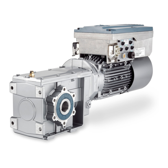
Siemens SINAMICS G110M Operating Instructions Manual
Distributed converter for simogear geared motors
Hide thumbs
Also See for SINAMICS G110M:
- Operating instructions manual (382 pages) ,
- Original instructions manual (344 pages) ,
- Function manual (244 pages)


Need help?
Do you have a question about the SINAMICS G110M and is the answer not in the manual?
Questions and answers