
Related Manuals for gefran GPC


Summary of Contents for gefran GPC
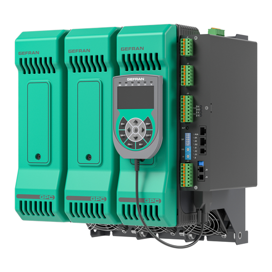
- Page 1 Advanced Power Controller CONFIGURATION AND PROGRAMMING MANUAL Software version 2.1x code: 81901A “MSW_GPC-40/600A”...
-
Page 3: Table Of Contents
TABLE OF CONTENTS Table of Contents ............. 1 3.9.4. Voltage on three-phase load ........28 3.9.5. Lower voltmeter input scale limit .......28 Preface ..............5 3.9.6. Upper voltmeter input scale limit .......28 3.9.7. Voltmeter input offset ..........29 Warnings and safety .................5 3.9.8. - Page 4 3.14.17. ALSTATE alarm status for single-phase loads and 3.20. Analog outputs ..............93 phase 1 of three-phase loads ........71 3.20.1. Types of analog output ..........94 3.14.18. ALSTATE_HB alarm status (phase 2 of two-phase/ 3.20.2. Analog output reference allocation ......95 three-phase loads and phase 3 of three-phase loads) .. 3.20.3.
- Page 5 Alarms ................138 4.4.1. Generic alarms AL1...AL8 ........138 4.4.2. HB alarm ..............139 4.4.3. HB alarm threshold teach-in function ......139 4.4.4. Heuristic power control ..........140 Using the GFW/GPC-OP keypad ....5.1. Description .................141 5.2. Legend ................141 5.3. Operations ................142 5.3.1. HOME screen ............142 5.3.2.
- Page 6 81901 “MSW_GPC-40/600A”_03-2021_ENG_page 4...
-
Page 7: Preface
PREFACE Warnings and safety Gefran always has the latest version of the Instruction Man- ual available for free downloads and in multiple languages Caution! Do not touch the terminals on the device at www.gefran.com. The current manual must be made when it is powered. - Page 8 81901 “MSW_GPC-40/600A”_03-2021_ENG_page 6...
-
Page 9: Liability Disclaimer
Liability disclaimer Although all the information in this document has been Gefran S.p.A. cannot be held in any way liable for damage carefully checked, Gefran S.p.A. cannot be held liable for to persons or property resulting from tampering or use that... - Page 10 81901 “MSW_GPC-40/600A”_03-2021_ENG_page 8...
-
Page 11: General Description
The instrument can be configured and programmed using The Advanced Power Controller is the ideal solution for a keypad (GFW/GPC-OP) or a PC installed with the special applications in heat treatment ovens, autoclaves, glass GF_eXpress application furnaces and dryers. - Page 12 81901 “MSW_GPC-40/600A”_03-2021_ENG_page 10...
-
Page 13: Commissioning
COMMISSIONING 2.1. Commissioning operations The simplest and safest way to commission GPC Advanced Power Controllers, after connecting the 24 Vdc power sup- ply and a PC to the CPU, is to use the GF_eXpress software and its “SMART CONFIGURATION” function. -
Page 14: First Power-On
Connect the analog and/or serial/fieldbus communica- tion signals. Power the GPC-M module via a 24 Vdc power supply. Once the GPC-M is switched on, the LEDs start turning on and off to indicate CPU initialisation. The following sequence is seen: All 8 LEDs on steadily at the same time for approx. -
Page 15: Configuration
Configuration and programming of the Advanced Power to correctly set the parameters needed to con- Controller can be performed with a keypad (GFW/GPC-OP) figure the Advanced Power Controller so that it or preferably with a PC installed with the special GF_eX- meets the application requirements. -
Page 16: Legend For Functional Parameter Diagrams
Single-node, in which GPC behaves as an individual single-phase, two-phase or three-phase controller. • Multi-node, in which GPC behaves as if it were several separate single-phase controllers (max 3). The difference consists in in the way it is used on the appli- cation and the way the parameters are addressed. -
Page 17: Functional Diagram Of Multi-Node Mode
(tens + units). The “2” is the address of the variable Ou.P in Multi-node mode. address is read-only. Up to 99 GPC devices can be installed in a serial network, 3.4.2.1. Custom Modbus memory map with a selection of standard node addresses from ‘01’... -
Page 18: Multi-Node Mode
The value set (Cod) on the rotary switches corresponds to 1026, i.e., the Modbus address of the first parameter to that of GPC-M; that of the other modules, if present, is in be accessed; sequence (Cod+1 for GPC-E1, Cod+2 for GPC-E2). -
Page 19: Connections
MainMenu → Global → Info → Cod 1070 16 bit 02.09 Global Short The parameter shows the identification code of the GPC device, which is set with the hexadecimal rotary switches. 1...99 min...max: 3.6.4. Serial port transmission speed Address GPC-OP... -
Page 20: Communication Error Timeout
MainMenu → E2 → Controls → C.E.m_3 4987 03.04.01 The parameter defines what happens to the power delivered from the output of the GPC device when a communication error occurs. Options: 0 = The power delivered is not changed 1 = The power delivered is forced to the value determined by the parameter C.E.P 3.6.7. -
Page 21: Analog Inputs
Offset Low-pass filter Input Analog input value signal 3 tP.A3 LS.A3, HS.A3 FLt.A3 In.A3 oFS.A3 3.7.2. Types of analog input Address GPC-OP Format Acronym GF_eXpress menu Single- Multi- menu node node Description MainMenu → Global → Inputs → Unsigned ■... -
Page 22: Analog Input Upper Scale Limit
3.7.4. Analog input upper scale limit Address GPC-OP Format Acronym GF_eXpress menu Single- Multi- menu node node Description MainMenu → Global → Inputs → Float ■ 1599 16 bit 04.05.03 HS.A1 Global s.p. 100.0 Analog input 1 → HS.A1 (####.#) MainMenu →... -
Page 23: Analog Input Process Value
The parameter shows the process value of analog input A1 or A2 or A3. min...max: 0.0...100.0 3.8. Measuring load current The Advanced Power Controller is able to measure the GPC model Rated current H.tA current input from the controlled load, whether single-phase GPC 40 40 A 80.0... - Page 24 *) limits depend on the current rating of the device Three-phase load Ammeter input Scale limits * Offset Low-pass filter SCR ON L.tA_1, H.tA_1 o.tA_1 Ft.tA_1 phase 1 (L1) GPC-M Filtered input Control output RMS current I.on_1 Ou.P_1 Ld.A_1 Ammeter input Scale limits * Offset Low-pass filter SCR ON L.tA_2, H.tA_2...
-
Page 25: Ammeter Input Lower Scale Limit
3.8.1. Ammeter input lower scale limit Address GPC-OP Format Acronym GF_eXpress menu Single- Multi- menu node node Description MainMenu → M → Inputs → CT input → 1770 04.08.01 Lt.A_1 MainMenu → E1 → Inputs → CT input → Float L.tA... -
Page 26: Transformation Ratio For External Ct Input
3.8.4. Transformation ratio for external CT input Address GPC-OP Format Acronym GF_eXpress menu Single- Multi- menu node node Description MainMenu → M → Inputs → CT input → 1417 04.08.05 r.tA_1 MainMenu → E1 → Inputs → CT input →... -
Page 27: Power Factor
3.8.8. Power factor Address GPC-OP Format Acronym GF_eXpress menu Single- Multi- menu node node Description MainMenu → M → Status → CoS.F_1 1740 Float CoS.F MainMenu → E1 → Status → CoS.F_2 2764 16 bit (####.#) 4812 MainMenu → E2 → Status → CoS.F_3 The parameter shows the power factor of the device M or E1 or E2. -
Page 28: Measuring Load Voltage
3.9. Measuring load voltage The Advanced Power Controller is able to measure the The following diagrams show the processing sequences for RMS voltage value of the controlled load, whether sin- the initial voltage value. gle-phase or three-phase. It can also measure the voltage of a two-phase load. -
Page 29: Rms Load Voltage
H.tVL_3 Load voltage * Average Ld.V.t *) with BIPHASE command the value Ld.V_3 is obtained as the average of the values Ld.V_1 and Ld.V_2 3.9.1. RMS load voltage Address GPC-OP Format Acronym GF_eXpress menu Single- Multi- menu node node... -
Page 30: Load Voltage With Output Activated
The parameter shows the upper limit of the measurement scale used for the TV_LOAD voltage transformer input. The parameter is present if the VLOAD option exists. The upper limit default value depends on the controller model: GPC model Rated voltage H.tVL... -
Page 31: Voltmeter Input Offset
A voltage presence check is active for each phase, which of the three line voltages. switches off the GPC module if it detects incorrect values. For three-phase loads, unbalance diagnostics is provided The following diagrams show the processing sequences of to switch off the load and indicate the fault with LEDs. - Page 32 Single-phase load Filtered input Voltme- Scale limits Offset Low-pass filter Generic voltage ter input alarms L.tV, H.tV o.tV Ft.tV I.VF Voltmeter input voltage I.tV Mains frequency FrEq Three-phase load Phase Filtered input 1 line Generic Scale limits Offset Low-pass filter voltage voltmeter L.tV_1, H.tV_1...
-
Page 33: Lower Vt Voltmeter Input Scale Limit
3.10.1. Lower VT voltmeter input scale limit Address GPC-OP Format Acronym GF_eXpress menu Single- Multi- menu node node Description MainMenu → M → Inputs → 1477 04.09.01 VT line input → L.tV_1 MainMenu → E1 → Inputs → Float L.tV... -
Page 34: Three-Phase Line Unbalance Threshold
3.10.4. Three-phase line unbalance threshold Address GPC-OP Format Acronym GF_eXpress menu Single- Multi- menu node node Description Unsigned Global MainMenu → Global → Controls → Unb.1 R/W ■ 1280 16 bit 07.01.04 Unb.1 Short Unsigned ■ 1281 16 bit 07.01.05 Unb.2... -
Page 35: Grid Frequency
Address GPC-OP Format Acronym GF_eXpress menu Single- Multi- menu node node Description 1726 16 bit 01.01.07 Global VOLTAGE_STATUS Unsigned The stored bytes contain information about the line voltage status and other operating states of the device. Each bit contains a specific piece of information, as shown in the table. -
Page 36: 3.11. Measuring The Power On The Load And Energy Consumed
3.11. Measuring the power on the load and energy consumed The Advanced Power Controller is able to measure the in- The load impedance value of the individual module is also stantaneous active power value on the load and the energy available;... -
Page 37: Power On Load
3.11.1. Power on load Address GPC-OP Format Acronym GF_eXpress menu Single- Multi- menu node node Description MainMenu → M → Status → Ld.P_1 1904 01.02.07 Float32 Ld.P MainMenu → E1 → Status → Ld.P_2 2928 32 bit 01.03.07 (####.#) 4976 01.04.07... -
Page 38: E2 Energy Consumed
3.11.6. E2 energy consumed Address GPC-OP Format Acronym GF_eXpress menu Single- Multi- menu node node Description MainMenu → M → Status → Ld.E2_1 1534 01.02.10 Unsigned ■ Ld.E2 MainMenu → E1 → Status → Ld.E2_2 2558 32 bit 01.03.10 4606 01.04.10... -
Page 39: E2 Energy Consumption Meter Reset
3.11.10. E2 energy consumption meter reset Address GPC-OP Format Acronym GF_eXpress menu Single- Multi- menu node node Description MainMenu → M → Expert → 1139 Bit → BIT_RESET_LDE2_1 BIT_ MainMenu → E1 → Expert → RESET_ 2163 Bit → BIT_RESET_LDE2_2 LDE2 MainMenu →... - Page 40 Digital input enable Digital Digital input status function selected Input 1 BIT_STATUS_DIG1 dIG.1 function processing flow by selecting PWM with dIG1 PWM input PWM input PWM input value timeout filter In.Pwm1 PWm.t1 Ft.PWm1 Digital input enable Digital Digital input status function selected BIT_STATUS_DIG2...
-
Page 41: Definition Of Digital Input Types
3.12.1. Definition of digital input types Address GPC-OP Format Acronym GF_eXpress menu Single- Multi- menu node node Description MainMenu → Global → Inputs → Unsigned ■ 1409 16 bit 04:17:05 tP.dIG Global Digital inputs → tP.dIG Short The parameter sets the types of all digital inputs. -
Page 42: Digital Input Function
HB alarm threshold calibration On leading edge FUSE_OPEN / SHORT_CIRCUIT_CURRENT alarm reset On state Reference calibration of feedback selected by hd.6 for GPC-M On leading edge Reference calibration of feedback selected by hd.6 for GPC-E1 On leading edge Reference calibration of feedback selected by hd.6 for GPC-E2... -
Page 43: Pwm Input Timeout
3.12.5. PWM input timeout Address GPC-OP Format Acronym GF_eXpress menu Single- Multi- menu node node Description MainMenu → Global → Inputs → Float ■ 1380 16 bit 04:17:09 PWm.t1 Global sec. 0.01 Digital inputs → PWm.t1 (####.#) MainMenu → Global → Inputs →... -
Page 44: Generic Alarms Al1
3.13. Generic alarms AL1 ... AL8 The Advanced Power Controller has 8 alarms (AL1...AL8) Alarms can be configured to be triggered if the reference per module, described as generic, which can take on vari- threshold is exceeded (value read greater than maximum ous functions threshold or less than minimum threshold), or if the thresh- old value is not reached (value read less than maximum... -
Page 45: Enable Alarms
AL7: Maximum current alarm with active output with time delay. • AL8: Alarm disabled. The minimum and maximum values depend on the current and voltage ratings of the device. 3.13.1. Enable alarms Address GPC-OP Format Acronym GF_eXpress menu Single- Multi- menu node node Description MainMenu →... -
Page 46: Generic Alarm Reference Variable Selection
3.13.2. Generic alarm reference variable selection Address GPC-OP Format Acronym GF_eXpress menu Single- Multi- menu node node Description MainMenu → M → Alarms → 1239 05.01.02 AL1...AL8 alarms → AL1 → A1.r_1 MainMenu → E1 → Alarms → Unsigned ■... - Page 47 Description The parameter sets the reference variable for the generic alarms AL1...AL8 of modules GPC-M, GPC-E1 and GPC-E2. The alarm and module concerned depend on the address used. The range of valid values and the position of the decimal point for alarm threshold and hysteresis can vary depending on the reference variable chosen for the alarm.
-
Page 48: Alarm Threshold
3.13.3. Alarm threshold Address GPC-OP Format Acronym GF_eXpress menu Single- Multi- menu node node Description MainMenu → M → Alarms → 1036 05.01.18 AL1...AL8 alarms → AL1 → AL.1_1 MainMenu → E1 → Alarms → ■ AL.1 2060 16 bit 05.02.18... - Page 49 Description The parameter sets the alarm threshold for generic alarms AL1...AL8 of modules GPC-M, GPC-E1 and GPC-E2. The threshold and mod- ule concerned depend on the address used. The default values may depend on the controller model. *) The range of valid values for the threshold and the position of the decimal point may vary according to the reference variable chosen for the alarm Ax.r (with x = 1...8).
-
Page 50: Alarm Hysteresis
05.03.33 AL1...AL8 alarms → AL8 → Hy.8_3 The parameter sets the hysteresis for generic alarms AL1...AL8 of modules GPC-M, GPC-E1 and GPC-E2. The alarm and module con- cerned depend on the address used. *) The range of valid values for the threshold and the position of the decimal point may vary according to the reference variable chosen for the alarm Ax.r (with x = 1...8). -
Page 51: Alarm Type
3.13.5. Alarm type Address GPC-OP Format Acronym GF_eXpress menu Single- Multi- menu node node Description MainMenu → M → Alarms → 1430 05.01.10 AL1...AL8 alarms → AL1 → A1.t_1 MainMenu → E1 → Alarms → Unsigned ■ A1.t 2454 16 bit 05.02.10... - Page 52 Multi- menu node node Description The parameter sets the alarm type for generic alarms AL1...AL8 of modules GPC-M, GPC-E1 and GPC-E2. The alarm and module con- cerned depend on the address used. Options: Direct (maximum) or Normal or Symmetri- Index...
-
Page 53: Direct Setting Of A Direct Or Reverse Alarm
3.13.6. Direct setting of a direct or reverse alarm Address GPC-OP Format Acronym GF_eXpress menu Single- Multi- menu node node Description MainMenu → M → Expert → 1070 Bit → BIT_AL1_DIR_INV_1 BIT_ MainMenu → E1 → Expert → ■ AL1_ 2094 Bit →... -
Page 54: Direct Setting Of An Absolute Or Relative Alarm
3.13.7. Direct setting of an absolute or relative alarm Address GPC-OP Format Acronym GF_eXpress menu Single- Multi- menu node node Description MainMenu → M → Expert → 1071 Bit → BIT_AL1_ABS_REL_1 BIT_ AL1_ MainMenu → E1 → Expert → ■... -
Page 55: Direct Setting Of A Normal Or Symmetrical Alarm
3.13.8. Direct setting of a normal or symmetrical alarm Address GPC-OP Format Acronym GF_eXpress menu Single- Multi- menu node node Description MainMenu → M → Expert → 1072 Bit → BIT_AL1_NOR_SYM_1 BIT_ AL1_ MainMenu → E1 → Expert → ■... -
Page 56: Direct Setting Of Alarm Enabling At Startup
3.13.9. Direct setting of alarm enabling at startup Address GPC-OP Format Acronym GF_eXpress menu Single- Multi- menu node node Description MainMenu → M → Expert → 1073 BIT_ Bit → BIT_AL1_DISABLE_PWON_1 AL1_ MainMenu → E1 → Expert → ■ 2097 DISA- Bit →... -
Page 57: Direct Setting Of Alarm Memory Activation
3.13.10. Direct setting of alarm memory activation Address GPC-OP Format Acronym GF_eXpress menu Single- Multi- menu node node Description MainMenu → M → Expert → 1074 Bit → BIT_AL1_MEM_1 BIT_ MainMenu → E1 → Expert → ■ 2098 AL1_ Bit → BIT_AL1_MEM_2 MainMenu →... -
Page 58: Alarm Validation Power
MainMenu → E2 → Alarms → 4163 05.03.41 AL1...AL8 alarms → AL8 → A8.P_3 The parameter sets the validation power for generic alarms AL1...AL8 of modules GPC-M, GPC-E1 and GPC-E2. The alarm and module concerned depend on the address used. min...max: 0.0...100.0... -
Page 59: Alarm Status Reading
MainMenu → E2 → Expert → 4117 Bit → BIT_STATUS_AL8_3 The parameter shows the status of generic alarms AL1...AL8 of modules GPC-M, GPC-E1 and GPC-E2. The alarm and module con- cerned depend on the address used. Options: OFF = Alarm not active ON = Alarm on 81901A “MSW_GPC-40/600A”_03-2021_ENG_page 57... -
Page 60: Alarm Memory Reset
3.13.13. Alarm memory reset Address GPC-OP Format Acronym GF_eXpress menu Single- Multi- menu node node Description MainMenu → M → Expert → 1103 12.01.03 Bit → BIT_RESET_AL1_AL8_1 BIT_ MainMenu → E1 → Expert → ■ RESET_ 2127 12.02.03 Bit → BIT_RESET_AL1_AL8_2 AL1_AL8 MainMenu →... -
Page 61: 3.14. Hb (Heater Break) Alarms
In standard configuration, the SSR output is associated with the heating control of GPC-M, achieved by modulating the electrical power with the ON/OFF control according to the set cycle time. - Page 62 Functional diagram of HB alarm three-phase load Alarm threshold HB.tr_1 Filtered CT ammeter input value with HB alarm status phase 1 output 1 activated I.on_1 Filtered VT voltmeter input value I.VF_1 Alarm threshold HB.tr_2 HB alarm function Hb.F Filtered CT ammeter input value with HB alarm status output 2 activated...
- Page 63 Functional diagram of HB calibration in ZC - BF - HSC mode Ou.P power in Control output value calibration Ou.P Hb.Pw CT ammeter input CT reading in HB alarm value with output × HB calibration threshold activated Hb.tA A.Hb I.on % HB alarm threshold current read in HB cali-...
- Page 64 Functional diagram of HB calibration for infrared lamps Control output value HB calibration HB calibration Ou.P Ou.P power with IR lamp with IR lamp 100% Ir.tA.0 Ir.tV.0 CT ammeter input value with output activated HB calibration HB calibration I.on Ou.P power with IR lamp with IR lamp Ir.tA.1...
-
Page 65: Enabling Alarms
3.14.1. Enabling alarms See paragraph “3.13.1. Enable alarms”. 3.14.2. HB alarm function Address GPC-OP Format Acronym GF_eXpress menu Single- Multi- menu node node Description MainMenu → M → Alarms → 1081 05.04.01 HB alarm → Hb.F_1 MainMenu → E1 → Alarms →... -
Page 66: Delay Time For Hb Alarm Activation
Bit → BIT_CALIB_HB_3 This bit enables the alarm threshold calibration function for modules GPC-M, GPC-E1 and GPC-E2, depending on the address used. It should be noted that with a three-phase load, a different value can be set for the A.Hb alarm thresholds. In this mode an unbalanced three-phase load can be controlled without problems. -
Page 67: Hb Alarm Threshold Percentage
3.14.6. HB alarm threshold percentage Address GPC-OP Format Acronym GF_eXpress menu Single- Multi- menu node node Description MainMenu → M → Alarms → 1761 05.04.04 HB alarm → Hb.P_1 MainMenu → E1 → Alarms → Float ■ Hb.P 2785 16 bit 05.05.04... -
Page 68: Hb Calibration With Ir Lamp (Current)
3.14.10. HB calibration with IR lamp (current) Address GPC-OP Format Acronym GF_eXpress menu Single- Multi- menu node node Description MainMenu → M → Alarms → 1782 05.04.08 HB alarm → Ir.tA.0_1 MainMenu → E1 → Alarms → Float ■ Ir.tA.0... - Page 69 Address GPC-OP Format Acronym GF_eXpress menu Single- Multi- menu node node Description The parameter sets the HB calibration when using IR lamps. The following table shows the correspondence between acronym and per- centage of conduction current. Acronym Current Ir.tA.0 100 % conduction Ir.tA.1...
-
Page 70: Hb Calibration With Ir Lamp (Voltage)
3.14.11. HB calibration with IR lamp (voltage) Address GPC-OP Format Acronym GF_eXpress menu Single- Multi- menu node node Description MainMenu → M → Alarms → 1469 05.04.18 HB alarm → Ir.tV.0_1 MainMenu → E1 → Alarms → Float ■ Ir.tV.0... -
Page 71: Hb Alarm Threshold As Function Of Power On Load
Address GPC-OP Format Acronym GF_eXpress menu Single- Multi- menu node node Description The parameter sets the HB calibration when using IR lamps. The following table shows the correspondence between acronym and per- centage of conduction voltage. Acronym Voltage Ir.tV.0 100 % conduction Ir.tV.1... -
Page 72: Hb Alarm Status (Single-Phase Configuration Or Ct Phase 1 Two-Phase Or Three-Phase Configuration)
3.14.14. HB alarm status (single-phase configuration or CT phase 1 two-phase or three- phase configuration) Address GPC-OP Format Acronym GF_eXpress menu Single- Multi- menu node node Description MainMenu → M → Expert → 1100 Bit → BIT_STATUS_HB_1 BIT_ MainMenu → E1 → Expert →... -
Page 73: Alstate Alarm Status For Single-Phase Loads And Phase 1 Of Three-Phase Loads
3.14.17. ALSTATE alarm status for single-phase loads and phase 1 of three-phase loads Address GPC-OP Format Acronym GF_eXpress menu Single- Multi- menu node node Description MainMenu → M → Status → 1536 ALSTATE_1 MainMenu → E1 → Status → 2560... -
Page 74: Current)
I.on dG.F Update frequency Filtered VT voltme- Alarm status dG.t ter input value NO_CURRENT I.VF 3.15.1. Enable POWER_FAULT alarms Address GPC-OP Format Acronym GF_eXpress menu Single- Multi- menu node node Description MainMenu → M → Alarms → 1684 05.07.01 PF alarms →... -
Page 75: Hb, Ssr_Short, No_Voltage And No_Current
3.15.2. SSR_SHORT update frequency Address GPC-OP Format Acronym GF_eXpress menu Single- Multi- menu node node Description MainMenu → Global → Alarms → Unsigned ■ 1685 16 bit 05.07.03 dG.t Global sec. PF alarms → dG.t Short The parameter sets the update frequency for the SSR_SHORT alarm, which corresponds to the delay time for activation of the alarm. -
Page 76: Ssr_Short Alarm Status (Single-Phase Configuration Or Ct Phase 1 Two-Phase Or Three-Phase Configuration)
3.15.6. SSR_SHORT alarm status (single-phase configuration or CT phase 1 two-phase or three-phase configuration) Address GPC-OP Format Acronym GF_eXpress menu Single- Multi- menu node node Description MainMenu → M → Expert → 1120 BIT_ Bit → BIT_STATUS_SSR_SHORT_1 STA- MainMenu → E1 → Expert →... -
Page 77: Voltage Alarm Status (Single-Phase Configuration Or Ct Phase 1 Two-Phase Or Three-Phase Configuration)
3.15.9. NO_VOLTAGE alarm status (single-phase configuration or CT phase 1 two-phase or three-phase configuration) Address GPC-OP Format Acronym GF_eXpress menu Single- Multi- menu node node Description MainMenu → M → Expert → 1123 Bit → BIT_STATUS_NO_VOLTAGE_1 BIT_ MainMenu → E1 → Expert →... -
Page 78: Current Alarm Status (Single-Phase Configuration Or Ct Phase 1 Two-Phase Or Three-Phase Configuration)
3.15.12. NO_CURRENT alarm status (single-phase configuration or CT phase 1 two-phase or three-phase configuration) Address GPC-OP Format Acronym GF_eXpress menu Single- Multi- menu node node Description MainMenu → M → Expert → 1126 Bit → BIT_STATUS_NO_CURRENT_1 BIT_ MainMenu → E1 → Expert →... -
Page 79: 3.16. Thermal Protection Alarms
3.16. Thermal protection alarms Each SSR power module of the Advanced Power Controller The In.Ntc.SSR.Max1 and In.Ntc.AIR.Max1 temperatures has: can be reset with a command. • a temperature sensor for the internal heat sink; • two additional temperature sensors connected to the The OVER_HEAT alarm is activated when at least one of LINE and LOAD terminals;... -
Page 80: Ssr Heat Sink Temperature Value
3.16.1. SSR heat sink temperature value Address GPC-OP Format Acronym GF_eXpress menu Single- Multi- menu node node Description MainMenu → M → Expert → 1679 Status → In.Ntc.SSR_1 MainMenu → E1 → Expert → In.Ntc. Float 2703 16 bit °C Status →... -
Page 81: Maximum Temperature Value Of Ssr Heat Sink
Max2 MainMenu → E2 → Expert → 4425 Status → In.Ntc.AIR.Max2_3 The parameter shows the maximum temperature of the power board shown by the air temperature sensor of GPC-M, GPC-E1 and GPC-E2. The differences are: • In.Ntc.AIR.Max1 shows the maximum temperature value since the last reset To reset the parameter see paragraph “3.16.8. -
Page 82: Status Reading (Status4)
3.16.7. Status reading (STATUS4) Address GPC-OP Format Acronym GF_eXpress menu Single- Multi- menu node node Description MainMenu → M → 1658 01.02.19 Status → STATUS4_1 MainMenu → E1 → STA- Unsigned 2682 16 bit 01.03.19 TUS4 Status → STATUS4_2 Short MainMenu →... -
Page 83: 3.17. Fuse_Open And Short_Circuit_Current Alarms
The SHORT_CIRCUIT_CURRENT alarm is activated when the peak current on the load exceeds the maximum permit- ted value (corresponding to twice the device’s rated current) 3.17.1. Number of automatic restarts Address GPC-OP Format Acronym GF_eXpress menu Single- Multi- menu... -
Page 84: 3.18. General Description Of The Outputs
The status of outputs OUT1...OUT10 can be acquired by optional relay, logic and analog outputs. serial communication using bit variables. In standard configuration these outputs perform the HB alarm function for GPC-M, GPC-E1 and GPC-E2 respec- The following configuration parameters are also linked to tively. the outputs: In this configuration the rL.2 reference signals of each... - Page 85 Ct.1_1 * rL.1_1 OUT1 OUT1 Cycle time Status Ct.2_1 ** rL.2_1 Allocation of reference signal Status Reference rL.3_1 signals rL.1_1 BIT_STATUS_ OUT2 GPC-M rL.2_1 OUT2 Status rL.3_1 rL.5_1 rL.4_1 rL.5_1 rL.6_1 Status rL.4_1 Status BIT_STATUS_ OUT3 OUT3 rL.6_1 Cycle time Status Ct.1_2 *...
-
Page 86: 3.19. Allocation Of Reference Signals To Outputs
3.19. Allocation of reference signals to outputs 3.19.1. Allocation of reference signal Address GPC-OP Format Acronym GF_eXpress menu Single- Multi- menu node node Description 1184 06.01.01 MainMenu → M → Outputs → rL.1_1 Unsigned MainMenu → E1 → Outputs → rL.1_2 ■... - Page 87 Address GPC-OP Format Acronym GF_eXpress menu Single- Multi- menu node node Description The parameter sets the allocation of the value of another parameter, or a function of parameters, to the reference signal rL.x, with x rang- ing from 1 to 6. The reference signal must be understood as an internal status.
-
Page 88: Out Cycle Time
3.19.2. OUT cycle time Address GPC-OP Format Acronym GF_eXpress menu Single- Multi- menu node node Description MainMenu → M → Outputs → Ct.1_1 1033 06.01.07 ■ Ct.1 MainMenu → E1 → Outputs → Ct.1_2 2057 16 bit 06.02.07 Float sec. -
Page 89: Status Rl
Bit → BIT_STATUS_RL6_2 MainMenu → E2 → Expert → 4113 Bit → BIT_STATUS_RL6_3 The bit shows the status of the reference signals rL.1...rL.6 of modules GPC-M, GPC-E1, and GPC-E2, depending on the address used. Options: = Signal off = Signal on... -
Page 90: Allocation Of Physical Outputs
GPC-E1 present. In the three-phase configuration the status of the physical output OUT1 is copied. out.3 is only available with GPC-E2 present. In the three-phase configuration the status of the physical output OUT1 is copied. -
Page 91: Alarm Status Masks For Custom Output 9
3.19.6. Alarm status masks for custom output 9 Address GPC-OP Format Acronym GF_eXpress menu Single- Multi- menu node node Description MainMenu → Global → Expert → Unsigned ■ 1934 16 bit Global 4095 OCM.9_1 Output Custom → OCM.9_1 Short MainMenu → Global → Expert →... -
Page 92: Status Reset To Last Activation Of Custom Out9
3.19.8. Status reset to last activation of custom OUT9 Address GPC-OP Format Acronym GF_eXpress menu Single- Multi- menu node node Description BIT_ MainMenu → Global → Expert → RESET_ 1134 Global Bit → BIT_RESET_OUT9_CUSTOM OUT9_ CUSTOM The bit resets the status to the last activation of custom output 9. -
Page 93: Rl.x (Maskout_Out) Status
3.19.11. rL.x (MASKOUT_OUT) status Address GPC-OP Format Acronym GF_eXpress menu Single- Multi- menu node node Description MASK_ MainMenu → Global → Status → Unsigned 1688 16 bit 01.01.10 Global MASK_OUT Short The parameter bits show the status of the physical outputs. -
Page 94: Status4 Stored With Custom Output Activation
3.19.13. STATUS4 stored with custom output activation Address GPC-OP Format Acronym GF_eXpress menu Single- Multi- menu node node Description MainMenu → Global → Expert → Output 1323 Custom → STATUS4_FOR_OUT09_1 STATUS4_ MainMenu → Global → Expert → Output Unsigned 2347... -
Page 95: 3.20. Analog Outputs
3.20. Analog outputs The Advanced Power Controller has 3 optional analog out- puts that allow the value of analog quantities to be retrans- mitted. The engineering value of the quantity is limited to the set scale values and reparameterisation is applied according to the selected output type. -
Page 96: Types Of Analog Output
3.20.1. Types of analog output Address GPC-OP Format Acronym GF_eXpress menu Single- Multi- menu node node Description MainMenu → Global → Unsigned ■ 1889 16 bit 06.05.01 tP.AO1 Global Outputs → Analog output1 → tP.A01 Short MainMenu → Global →... -
Page 97: Analog Output Reference Allocation
Ld.V (load voltage) of GPC-E1 6553.5 Ld.V (load voltage) of GPC-E2 6553.5 Ld.V.t (voltage on three-phase load) 6553.5 Ld.A (current in load) of GPC-M 6553.5 Ld.A (current in load) of GPC-E1 6553.5 Ld.A (current in load) of GPC-E2 6553.5 Ld.A.t (current on three-phase load) 6553.5... -
Page 98: Lower Analog Output Scale Limit
3.20.3. Lower analog output scale limit Address GPC-OP Format Acronym GF_eXpress menu Single- Multi- menu node node Description MainMenu → Global → Float ■ 1895 16 bit 06.05.03 LS.A01 Global s.p. Outputs → Analog output1 → LS.AO1 (####.#) MainMenu → Global →... -
Page 99: Analog Output Value
3.20.6. Analog output value Address GPC-OP Format Acronym GF_eXpress menu Single- Multi- menu node node Description MainMenu → Global → Float 1901 16 bit 01.01.11 Out.A01 Global Status → OUT.A01 (####.# MainMenu → Global → Float 01.01.12 Out.A02 Global 1902 16 bit Status →... - Page 100 SPU_x RMS current limitation hd.5_x Fu.tA_x Gradient for Ø Digital input 3 control output In.Pwm3 G.Out_x Power from GPC-M FW_POWER BIT_SOFTWARE_ON_OFF_x STATUS_W_x dIG1, dIG.2, dIG.3, dIG.4 Power from GPC-E1 FW_POWER Power from GPC-E2 Ou.P_x FW_POWER with x = 1...3 81901 “MSW_GPC-40/600A”_03-2021_ENG_page 98...
-
Page 101: Reference Power
Index Selection Power from analog input 1 (In.A1) Power from digital input 1 (In.Pwm1) Power from GPC-M (FW_POWER). With “slave” module operation: • The reference power of a “slave” module in automatic operation is the power of a “master” module in automatic or manual operation. -
Page 102: Power Output Percentage
3.21.4. Power output percentage Address GPC-OP Format Acronym GF_eXpress menu Single- Multi- menu node node Description MainMenu → M → Controls → P.PEr_1 1789 07.02.03 Float ■ P.PEr MainMenu → E1 → Controls → P.PEr_2 2813 16 bit 07.03.03 100.0 (####.#) -
Page 103: Automatic - Manual Control
Ou.P (see paragraph from manual mode will be based upon the reference power “3.21.2. Output power value”). (SPU_x) and the control output gradient (G.out). 3.22.1. Manual power Address GPC-OP Format Acronym GF_eXpress menu Single- Multi- menu... -
Page 104: Status (Status_W)
3.22.3. Status (STATUS_W) Address GPC-OP Format Acronym GF_eXpress menu Single- Multi- menu node node Description MainMenu → M → Controls → 1329 07.02.14 STATUS_W_1 MainMenu → E1 → Controls → STA- Unsigned ■ 2353 16 bit 07.03.14 TUS_W Short STATUS_W_2 MainMenu →... -
Page 105: Enabling Manual Power Correction And Storage
3.23.3. Enabling manual power correction and storage Address GPC-OP Format Acronym GF_eXpress menu Single- Multi- menu node node Description Unsigned MainMenu → Global → Controls → SP.r ■ 1042 16 bit 07.01.01 SP.r Global Short The parameter enables manual power correction and storage. -
Page 106: Software Shutdown
• HB alarms are reset. paragraph “3.12.2. Digital input status”). • The generic alarms AL1...AL8 can be enabled or disa- bled via the parameter oFF.t. 3.25.1. Software startup/shutdown Address GPC-OP Format Acronym GF_eXpress menu Single- Multi- menu node node Description MainMenu →... -
Page 107: 3.26. Other Functions
3.26. Other functions 3.26.1. Operating hour meter Address GPC-OP Format Acronym GF_eXpress menu Single- Multi- menu node node Description MainMenu → M → Status → OH.c_1 1420 01.02.13 Unsigned ■ 2444 32 bit 01.03.13 OH.c MainMenu → E1 → Status → OH.c_2 MainMenu →... -
Page 108: 3.27. Power Control Modes
3.27. Power control modes The Advanced Power Controller modulates the power deliv- duction cycles, which can be set from 1 to 10. ery with two modes: In the case of a three-phase load (star without neutral or • by changing the phase angle (PA mode); closed delta), a value of bF.Cy >= 5 must be set to ensure •... -
Page 109: Enabling Trigger Modes
3.27.1. Enabling trigger modes Address GPC-OP Format Acronym GF_eXpress menu Single- Multi- menu node node Description MainMenu → M → Power controls → 1727 09.01.01 hd.5_1 MainMenu → E1 → Power controls → Unsigned ■ hd.5 2751 16 bit 09.02.01... -
Page 110: Maximum Rms Current Limit In Steady State
MainMenu → E2 → Power controls → 4803 09.03.02 Fu.tA_3 The parameter sets the maximum limit of the RMS current at steady state. The default value depends on the size of the controller: Size GPC-M, GPC-E1, Default GPC-E2 40 A 40.0 60 A 60.0... -
Page 111: 3.28. Softstart
PS.tA. This function is useful in the event of a short circuit on the load or of loads with high temperature coefficients in order 3.28.1. Maximum phase of the phase softstart ramp Address GPC-OP Format Acronym GF_eXpress menu Single- Multi-... -
Page 112: Minimum Non-Conduction Time For Ramp Reactivation
4802 09.03.06 PS.tA_3 The parameter sets the maximum peak current limit during the phase softstart ramp. The default value depends on the size of the controller: Size Default GPC-M, GPC-E1, GPC-E2 40 A 110.0 60 A 170.0 100 A 280.0 150 A 420.0... -
Page 113: Phase Softstart Ramp Restart
3.28.5. Phase softstart ramp restart Address GPC-OP Format Acronym GF_eXpress menu Single- Multi- menu node node Description MainMenu → M → Expert → Bit → 1132 BIT_SOFTSTART_RESTART_1 BIT_ MainMenu → E1 → Expert → Bit → SOFTS- 2156 TART_RE- BIT_SOFTSTART_RESTART_2 START MainMenu →... -
Page 114: 3.29. Delay Triggering
Delay Triggering is a function that inserts a trigger delay on the first cycle with inductive loads in start modes ZC and BF. The startup delay is expressed in degrees and can be set in the dL.t parameter. 3.29.1. Delay triggering Address GPC-OP Format Acronym GF_eXpress menu Single- Multi- menu... -
Page 115: 3.30. Automatic Firing Change Function
Index +8 = Enabling of Firing Change function from digital inputs. Index +16 = Enabling of Firing Change function from serial communication. Index +32 = GPC-E1 follows GPC-M (only applies if GPC-E1 is enabled). Index +64 = GPC-E2 follows GPC-M (only applies if GPC-E2 is enabled). -
Page 116: Current Threshold For Activating Firing Change
3.30.2. Current threshold for activating Firing Change Address GPC-OP Format Acronym GF_eXpress menu Single- Multi- menu node node Description MainMenu → M → Power controls → 1926 09.04.02 FC.thr_1 MainMenu → E1 → Power controls → Float ■ FC.thr 2950 16 bit 09.05.01... -
Page 117: Firing Change Status Set Via Serial
3.30.5. Firing Change status set via serial Address GPC-OP Format Acronym GF_eXpress menu Single- Multi- menu node node Description MainMenu → M → Expert → Virtual → 1921 SERIAL_FC_1 MainMenu → M → Expert → Virtual → SERI- Unsigned 2945... -
Page 118: 3.31. Feedback Mode
(value stored in the parameter riF.V, expressed in data-sheet (see GPC Installation Guide Document). Vrms) The voltage value maintained on the load is equal to the... -
Page 119: Enabling Feedback Mode
3.31.1. Enabling feedback mode Address GPC-OP Format Acronym GF_eXpress menu Single- Multi- menu node node Description MainMenu → M → Power controls → 1732 09.01.10 hd.6_1 MainMenu → E1 → Power controls → Unsigned ■ hd.6 2756 16 bit 09.02.10 Short hd.6_2... -
Page 120: Maximum Power Feedback Correction
3.31.4. Maximum power feedback correction Address GPC-OP Format Acronym GF_eXpress menu Single- Multi- menu node node Description MainMenu → M → Power controls → 1757 09.01.12 Cor.P_1 MainMenu → E1 → Power controls → Float ■ Cor.P 2781 16 bit 09.02.12... -
Page 121: Feedback Response Speed
3.31.8. Feedback response speed Address GPC-OP Format Acronym GF_eXpress menu Single- Multi- menu node node Description MainMenu → M → Power controls → 1765 09.01.17 Fb.lt_1 MainMenu → E1 → Power controls → Float ■ Fb.lt 2813 16 bit 09.02.17 (####.#) -
Page 122: 3.32. Heuristic Power Control
MainMenu → Global → Powers → hd.3 Short The parameter enables the heuristic power control of GPC-M, GPC-E1 and GPC-E2. Setting hd.3 = 0 disables heuristic power control for all modules. Enabling only applies to GPCs with OUT1...OUT3 outputs with slow cycle time (1...200 seconds). -
Page 123: 3.33. Heterogeneous Power Control
16 bit 09.08.01 hd.4 Global MainMenu → Global → Powers → hd.4 Short The parameter enables heterogeneous power control of GPC-M, GPC-E1 and GPC-E2. Setting hd.4 = 0 disables heterogeneous power control for all modules. Options: GPC-M GPC-E1 GPC-E2 Index... -
Page 124: 3.34. Virtual Instrument Control
Virtual → S.In_3 The parameter sets the control of inputs from serial. The table shows the correspondence between bits and inputs. Inputs In.A1 In.A2 In.A3 NOTE: Inputs In.A1, In.A2 and In.A3 are only valid for GPC-M. min...max: 0...2047 81901 “MSW_GPC-40/600A”_03-2021_ENG_page 122... -
Page 125: Output Control From Serial
3.34.3. Output control from serial Address GPC-OP Format Acronym GF_eXpress menu Single- Multi- menu node node Description MainMenu → Global → Expert → Unsigned ■ 1249 16 bit 10.01.05 S.Ou Global Virtual → S.Ou Short The parameter sets the control of outputs from serial. The table shows the correspondence between bits and outputs. -
Page 126: Virtual Register Address Table
3.34.5. Virtual register address table Single-node Multi node Parameter Enabled resource Format Register name address address Alarm threshold AL1 for GPC-M 1365 word SERIAL_AL1_1 Alarm threshold AL2 for GPC-M 1366 word SERIAL_AL2_1 Alarm threshold AL3 for GPC-M 1367 word SERIAL_AL3_1 S.In_1... -
Page 127: Hw And Sw Information
3.35. HW and SW information The hardware and software of the Advanced Power Con- troller can be identified and its functioning checked by accessing the information registers. 3.35.1. Software version code Address GPC-OP Format Acronym GF_eXpress menu Single- Multi- menu... -
Page 128: Hardware Configuration Codes 1
MainMenu → Global → Info → C.Hd4 1217 16 bit 02.06 Global Short The register shows the hardware configuration (rating) of GPC-M, GPC-E1 and GPC-E2, according to the chosen address. Options: Configuration no power 40 A 60 A 100 A... -
Page 129: Fieldbus Board Firmware Version
3.35.5. Fieldbus board firmware version Address GPC-OP Format Acronym GF_eXpress menu Single- Multi- menu node node Description Float MainMenu → Global → Info → UPd.F 1717 16 bit 02.10 UPd.F Global (###.##) The log shows the firmware version of the Fieldbus board. -
Page 130: Jumper / Dip Switch Status
3.35.9. Jumper / DIP switch status Address GPC-OP Format Acronym GF_eXpress menu Single- Multi- menu node node Description MainMenu → Global → Info → Unsigned JUMPER_ 1370 16 bit 02.07 Global STATUS JUMPER_STATUS Short The register shows the status of the jumpers / DIP switches. The status of the individual jumper / DIP switch can determine a specific configuration. -
Page 131: Virtual Dip Switch Status
16 bit deviceID Global Short The register shows the device identifier (GPC) within the Modbus communication network. 3.35.14. LED operation The status of the LEDs RN, ER, DI1, DI2, O1, O2, O3 and BUT refers to the status of the corresponding parameter, with the following... -
Page 132: Rn - Er - Di1 - Di2 Led Function
Options: Index Function associated with the LED MAN/AUTO controller INDIG1 digital input configuration Serial dialogue 1 OUT 2 GPC-M status INDIG2 digital input configuration Error status Serial dialogue 2 INDIG3 digital input configuration INDIG4 digital input configuration By increasing the index by +16 the LED flashes if active (except index 8). -
Page 133: O1 - O2 - O3 Led Function
3.35.16. O1 - O2 - O3 LED function Address GPC-OP Format Acronym GF_eXpress menu Single- Multi- menu node node Description Unsigned MainMenu → Global → Leds → Ld.5 ■ 1646 16 bit 06.08.05 Ld.5 Global Short Unsigned ■ 1647 16 bit 06.08.06... -
Page 134: Status (Status)
3.35.19. Status (STATUS) Address GPC-OP Format Acronym GF_eXpress menu Single- Multi- menu node node Description MainMenu → M → Status → STATUS_1 1491 01.02.15 Unsigned STATUS MainMenu → E1 → Status → STATUS_2 2515 16 bit 01.03.15 Short 4563 01.04.15 MainMenu →... -
Page 135: Status 2 (Status2)
3.35.21. Status 2 (STATUS2) Address GPC-OP Format Acronym GF_eXpress menu Single- Multi- menu node node Description MainMenu → M → Status → STATUS2_1 1656 01.02.17 Unsigned 2680 01.03.17 MainMenu → E1 → Status → STATUS2_2 16 bit STATUS2 Short 4728 01.04.17... -
Page 136: 3.36. Key Functions
3.36. Key functions The Advanced Power Controller key allows the status of the Example of key use device to be changed. To activate the HB alarm calibration, start from normal op- A pressing and holding the key changes the status; the eration (RN LED flashing, BUT LED off): length of time key is pressed determines the new status. -
Page 137: Examples And Application Notes
EXAMPLES AND APPLICATION NOTES 4.1. Setting parameters LS.A1/LS.A2/LS.A3 and HS.A1/HS.A2/HS.A3 4.1.3. Input voltage range limited upwards The default values(LS.A1/LS.A2/LS.A3 = 0.0 and HS.A1/HS.A2/HS.A3 = 100.0) can be changed to obtain different assignments between the physical input value (V HS.A = 111.1 Ou.P or mA) and the engineering value (In.A1/In.A2/In.A3). -
Page 138: Using A Function Associated With The Digital Input And Via Serial
WARE_ON_ 305, bit 4 DIGITAL INPUT LEADING EDGE or on Power-On DIGITAL INPUT STATUS A/B STATUS GPC-M SERIAL WRITING A/B GPC-M STATUS A/B STATUS SERIAL GPC-M A/B STATUS GPC-E1 SERIAL WRITING A/B GPC-E1 STATUS A/B STATUS SERIAL GPC-E1 A/B STATUS... -
Page 139: Using Digital Input 1 To Enable Software Startup
The software startup function (OFF) can be used in fault or emergency conditions by resetting the control of the heating resistors. DIGITAL INPUT 1 STATUS ON/OFF STATUS GPC-M logical SERIAL WRITING ON/OFF GPC-M ON/OFF STATUS GPC-E1 logical SERIAL WRITING GPC-E1 ON/OFF ON/OFF STATUS GPC-E2 logical... -
Page 140: Alarms
4.4. Alarms 4.4.1. Generic alarms AL1...AL8 Generic alarms AL1…AL8 can be of 4 main types, shown below: Normal absolute alarm Normal absolute alarm (AL.1 inverse and absolute, AL.2 direct and absolute). Two alarm thresholds are set, AL.1 (lower threshold) and AL.2 (upper threshold), which correspond to two hysteresis AL.2 values, Hy.1 (positive) and Hy.2 (negative). -
Page 141: Hb Alarm
4.4.2. HB alarm Under the same conditions, if the power is delivered at 100%, the alarm will activate after 60 seconds. If the alarm The HB (Heater Break) alarm identifies load break or goes off during this interval, the time sum is reset. interruption through measurement of the current delivered The delay time set in Hb.t must exceed the cycle time of obtained by means of a current transformer. -
Page 142: Heuristic Power Control
If Ou.P_1 = 100%, Ou.P_2 = 100% and Ou.P_3 = 100% we Note: The function is only available when using have Ou.P = 200%. GPC model 3PH, with separate control of three As Ou.P > 100% we therefore have: individual single-phase loads. -
Page 143: Using The Gfw/Gpc-Op Keypad
A strip of magnetic material is located on the back of the eters and for diagnostics during operation. It can also be keypad so that it can be fixed to the front of the GPC-M or used to modify a large number of GPC parameters. -
Page 144: Operations
200 200 04.01 STATUS M 04.02 STATUS E1 04.03 STATUS E2 04.04 ANALOG In.A1 04.05 ANALOG In.A2 The screen gives a summary of the basic GPC parameters: • voltage on the load (V), • current in the load (A) •... -
Page 145: Changing A Numerical Parameter
A numerical parameter can be changed (only if R/W type), ALARM 1 of 3 as follows: STATUS4 bit1 GPC-E1 Press the E key when the parameter you want to change is displayed. TEMPERATURE SENSOR The cursor is activated, with inverted colours, on the digit of the parameter value corresponding to the unit. -
Page 146: Menu Structure
5.4. Menu structure 5.4.1. Main menu and 2nd level menu page 145 00 CURRENT LIMIT 00.01 CURRENT LIMIT M page 145 01 STATUS 00.02 CURRENT LIMIT E1 01:01 STATUS GLOBAL 00.03 CURRENT LIMIT E2 01:02 STATUS M 01:03 STATUS E1 01:04 STATUS E2 02 INFO 02.01 UPd: sw version... -
Page 147: 00 Current Limit - 3Rd Level Menu
5.4.2. 00 CURRENT LIMIT - 3rd level menu 00.01 CURRENT LIMIT M 00.02 CURRENT LIMIT E1 00.03 CURRENT LIMIT E2 08.01 SETTINGS 08.01 SETTINGS 08.01 SETTINGS 5.4.3. 01 STATUS - 3rd level menu 01.01 STATUS GLOBAL 01.01.01 Ld.V.t: load voltage 01.01.02 Ld.A.t: load current 01.01.03 Ld.P.t: load power 01.01.04 Ld.I.t: load imped. -
Page 148: 03 Comms - 3Rd Level Menu
5.4.4. 03 COMMS - 3rd level menu 03.01 SETTINGS GLOBAL 03.02 SETTINGS M 03.03 SETTINGS E1 03.01.01 bAu: baudrate 1 03.02.01 C.E.m: comm err mode 03.03.01 C.E.m: comm err mode 03.01.02 PAr: parity 1 03.02.02 C.E.P: comm err powr 03.03.02 C.E.P: comm err powr 03.01.03 bAu.2: baudrate 2 03.01.04 PAr.2: parity 2 03.01.05 F.SIZE: fieldbus size... -
Page 149: 05 Alarms - 3Rd Level Menu
04.17 DIGITAL GLOBAL 04:17:01 dIG.1: dig1 function 04:17:02 dIG.2: dig1 function 04:17:03 dIG.3: dig3 function 04:17:04 dIG.4: dig4 function 04:17:05 tP.dIG: input type 04:17:06 Ft.PWm1: time filter 04:17:07 Ft.PWm2: time filter 04:17:08 Ft.PWm3: time filter 04:17:09 PWm.t1: timeout 04:17:10 PWm.t2: timeout 04:17:11 PWm.t3: timeout 5.4.6. -
Page 150: 06 Outputs - 3Rd Level Menu
05.04 HB M 05.05 HB E1 05.06 HB E2 05.04.01 Hb.F: functions 05.05.01 Hb.F: functions 05.06.01 Hb.F: functions 05.04.02 Hb.t: time delay 05.05.02 Hb.t: time delay 05.06.02 Hb.t: time delay 05.04.03 A.Hb.1: threshold 05.05.03 A.Hb.1: threshold 05.06.03 A.Hb.1: threshold 05.04.04 Hb.P: percentage 05.05.04 Hb.P: percentage 05.06.04 Hb.P: percentage 05.04.05 Hb.tA: calibration... -
Page 151: 07 Controls - 3Rd Level Menu
06.08 LED 06.08.01 Ld.St: RN function 06.08.02 Ld.2 ER function 06.08.03 Ld.3 DI1 function 06.08.04 Ld.4 DI2 function 06.08.05 Ld.5 O1 function 06.08.06 Ld.6 O2 function 06.08.07 Ld.7 O3 function 06.08.08 Ld.8 BUT function 5.4.8. 07 CONTROLS - 3rd level menu 07.01 SETTINGS GLOBAL 07.01.01 SP.r: manual p. -
Page 152: Virtual - 3Rd Level Menu
5.4.10. 09 POWER CONTROLS - 3rd level menu 09.01 SSR MODE M 09.02 SSR MODE E1 09.03 SSR MODE E2 09.01.01 Hd.5: firing enabl 09.02.01 Hd.5: firing enabl 09.03.01 Hd.5: firing enabl 09.01.02 FU.tA: max current 09.02.02 FU.tA: max current 09.03.02 FU.tA: max current 09.01.03 bF.Cy: BF cycles 09.02.03 bF.Cy: BF cycles... -
Page 153: Custom Map - 3Rd Level Menu
5.4.12. 11 CUSTOM MAP - 3rd level menu 11.01 SETTINGS 11.01.01 CustomVar1 11.01.02 CustomVar2 11.01.03 CustomVar3 … 11.01.119 CustomVar119 11.01.120 CustomVar120 5.4.13. 12 COMMANDS - 3rd level menu 12.01 COMMANDS M 12.01.01 Power mode 12.01.02 Software On/Off 12.01.03 Reset AL1…AL8 12.01.04 Reset PF alarms 12.01.05 HB calib 12.01.06 Calibrated feedback... -
Page 154: Accessories
GF_eXpress software on CD-ROM, USB/485/TTL converter complete with cables for GF_eXK-2-0-0 F049095 connection to PC, Geflex, GTF, GFW and instrument. Programming panel for GFW/GPC Power Controllers. F068952 GFW/GPC LCD display 5 lines by 21 characters, keypad for recalling and setting parameters. - Page 156 GEFRAN spa via Sebina, 74 25050 Provaglio d’Iseo (BS) Italy Tel. +39 0309888.1 Fax +39 0309839063 info@gefran.com http://www.gefran.com...
Need help?
Do you have a question about the GPC and is the answer not in the manual?
Questions and answers