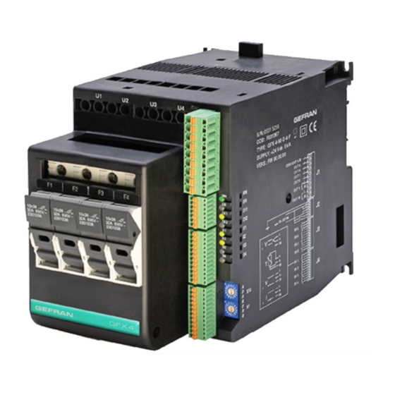
gefran GFX4-IR Series Installation And Operation Manual
4-zone modular power controller for ir lamps and inductive loads
Hide thumbs
Also See for GFX4-IR Series:
- Configuration manual (95 pages) ,
- Configuration and programming manual (88 pages) ,
- Installation and operation manual (2 pages)
Table of Contents
Advertisement
1 • PRELIMINARY INSTRUCTIONS ................................2
1.1 General Description .........................................................2
1.2 APreliminary instruction ...................................................2
2 • INSTALLAZIONE E COLLEGAMENTO .....................3
2.1 Electrical power supply ....................................................3
compatibility: .....................................................................3
of EMC..............................................................................3
2.4 Dimensions ......................................................................9
2.5 Installation ......................................................................10
2.6 Installation ...................................................................... 11
2.7 General description ........................................................12
2.8 Cleaning/checking or replacing the fan .........................13
2.9 Inserting the field bus interface board ...........................13
3 • ELECTRICAL CONNECTIONS ................................14
3.1 Power connections.........................................................14
3.2 Input/Output Connections ..............................................15
To differentiate the type and importance of the information in this User Manual, graphic reference symbols are used to make such information
easier to interpret.
Indicates contents of sections, general instructions, notes,
and other points to which the reader's attention needs to be
called.
Indicates a particularly delicate situation that could
affect the safety or correct operation of the controller,
or an instruction that MUST be followed to prevent
hazards.
Indicates a risk to the user's safety due to high voltage at
the points indicated.
80404L_MHW_GFX4-IR_03-2020_ENG
GFX4-IR
4-ZONE MODULAR POWER CONTROLLER FOR IR LAMPS AND INDUCTIVE LOADS
INDEX
GRAPHIC SYMBOLS
INSTALLATION AND
OPERATION MANUAL
Software version: 3.0x
code 80404L - 03/2020 - ENGLISH
3.3 Connector J1 outputs 5...10 ..........................................16
3.4 Connector J2 power supply, digital inputs 1, 2 ..............19
3.5 Connector J3 auxiliary inputs 5...8 ................................20
3.6 Connector J4 inputs 1...4 ...............................................21
3.7 Description of dip-switches ............................................22
3.8 Serial communication ports ...........................................23
3.9 Connection example: communication ports ..................30
3.10 Connection example: Power section .............................31
4.2 "AUTOBAUD SERIAL 1" sequence .............................46
4.1 ""AUTONODE PORT 1" sequence ..............................46
5 • TECHNICAL CHARACTERISTICS ..........................47
5.1 Voltage/Current Table ....................................................50
5.2 Dissipation curves ..........................................................50
5.3 Fuses / Fusesholders ....................................................50
6.1 Accessoires ....................................................................51
Indicates a suggestion based on the experience of
GEFRAN's Technical Personnel that could be
especially useful under certain circumstances.
Indicates a reference to Detailed Technical
Documents available on the GEFRAN website
www.gefran.com.
1
Advertisement
Table of Contents

Related Manuals for gefran GFX4-IR Series


Summary of Contents for gefran GFX4-IR Series
-
Page 1: Table Of Contents
Indicates contents of sections, general instructions, notes, Indicates a suggestion based on the experience of and other points to which the reader’s attention needs to be GEFRAN’s Technical Personnel that could be called. especially useful under certain circumstances. Indicates a particularly delicate situation that could... -
Page 2: Preliminary Instructions
Outputs 5...8 logic type It offers an exclusive combination of performance, reliability, and flexibility. Auxiliary inputs absent In particular, this new line of Gefran controllers is the ideal Fuse holders present solution for sectors demanding high performance and continuity of service, such as: See paragraph 2.1 “... -
Page 3: Installazione E Collegamento
DC. 2.2.2 LV (low voltage) conformity in compliance with Directive 2006/95/CE. GEFRAN S.p.A. assumes no liability for any damage to persons or property deriving from tampering, from incorrect or improper use, or from any use not conforming to the characteristics of the controller and to the instructions in this User Manual. - Page 4 Table 1 EMC Emission AC semiconductor motor controllers and conductors for EN 60947-4-3 non-motor loads EN 60947-4-3 Emission enclosure Class A Group 2 CISPR-11 compliant in firing mode single cycle and phase angle if EN 55011 external filter fitted Table 2 EMC Immunity Generic standards, immunity standard for industrial EN 60947-4-3 environments...
- Page 5 External EMC filters EMC filters are required in PA mode (Phase Angle, i.e., SCR trigger with phase angle modulation). The filter model and current level depend on the configuration and load used. The power filter must be connected as close to the GFX4-IR as possible. You can use a filter connected between the power supply line and the GFX4-IR or an LC group connected between each GFX4-IR output and the load.
- Page 6 Connection for 4 single-phase loads, 3-phase line with neutral Connection for 3 independent single-phase loads in open delta, 3-phase line without neutral Connection for 3-phase star load without neutral 80404L_MHW_GFX4-IR_03-2020_ENG...
- Page 7 Connection for 3-phase load in closed delta 80404L_MHW_GFX4-IR_03-2020_ENG...
- Page 8 INSULATION DIAGRAM 80404L_MHW_GFX4-IR_03-2020_ENG...
-
Page 9: Dimensions
imensions Fastening may be done on DIN guide (EN50022) or with (5MA). See Figure 1 and Figure 2. All dimensions are expressed in mm. Figure 1 Model without fuse holder Figure 2 Model with fuse holder 80404L_MHW_GFX4-IR_03-2020_ENG... -
Page 10: Installation
nstallation Attention: respect the minimum distances shown in Figure 3 to provide adequate air circulation. Figure 3 For correct attachment/release of the module on the DIN guide, do as follows: - keep the attach/release cursor pressed - insert/remove the module - release the cursor Figure 4 Figure 5... - Page 11 nstallation Products listed in table “UL508 SCCR FUSES TABLE “ are suitable for use on a circuit capable of delivering not more than 100,000 A rms Symmetrical Amperes, 480 Volts maximum when protected by fuses. Use fuses only According to UL508, test at 100.000A were carried out with class J fuses or RK5 rated xxxA (refer to table “SCCR fuse protection table”...
-
Page 12: General Description
eneral Description Figure 7 DIN bar for modules, for example, signal converters (only on models without fuse holders). access for screwdriver to power connector screws power connection terminals ventilation grill: DO NOT OBSTRUCT cursor for insertion/removal of DIN bar attachment screw seats for fastening module on plate dip switches for function configuration connectors for communication ports (Port1, Port2) -
Page 13: Cleaning/Checking Or Replacing The Fan
leaninG checkinG or replacinG the fan PERIODIC CLEANING Figure 10 Every 6-12 months (depending on the dust level of the installation) blow a compressed air jet through the upper rectangular cooling grilles (on the side opposite the fan). This will clean the internal heat dissipater and the cooling fan. -
Page 14: Electrical Connections
3 • ELECTRICAL CONNECTIONS ower connections Figure 12 model without fuse holder Figure 13 model with fuse holder F1,F2,F3,F4/N Line connection terminals F1,F2,F3,F4/N Line connection terminals U1,U2,U3,U4 Load connection terminals U1,U2,U3,U4 Load connection terminals Table 4 Model 30kW 60kW 80kW max current 32A (30A)* 57A (40A)*... -
Page 15: Input/Output Connections
nput utput onnections Use adequate compensated cable for thermocouple inputs. Respect polarity by avoiding junctions on the cables. If the thermocouple is grounded, the connection must be at a single point. For resistance thermometer inputs, use copper extension cables. Resistance must not exceed 20 ohm; avoid junctions on the cables. -
Page 16: Connector J1 Outputs 5
5...10 onnector outputs If auxiliary outputs (O5...O8), are present, connector J1a becomes J1. Figure 15 Connector J1 Table 7 0,2 - 2,5mm 24-14AWG 0,25 - 2,5mm 23-14AWG OUTPUTS 5...8 LOGIC / CONTINUOUS / ANALOG types Logic outputs: 18...36Vdc max 20mA Continuous outputs: voltage (default) 0/2...10V, max 25mA current 0/4...20mA, max 500Ω... - Page 17 When using the continuous “C” output option, voltage or current is set using jumper links on the board (Figure 17 refers). Figure 17 Connection for logic/continuous utputs voltage current GFX4 OUT-C GFX4 OUT-C 80404L_MHW_GFX4-IR_03-2020_ENG...
- Page 18 Outputs 5...8 triac type Triac outputs Vac = 24...230Vac, max 1A Figure 18 Connection scheme for triac outputs Com 5÷8 Table 9 Name Decription Outputs common Com 5-8 Output 5 Output 6 Output 7 Output 8 Outputs 5...8 relay type Outputs Out 5...8 relay Ir = 3A max, NO V = 250V/30Vdc cosj = 1;...
- Page 19 1, 2 onnector power supply DiGital inputs Figure 21 Table 12 0,14 - 0,5mm 28-20AWG 0,25 - 0,5mm 23-20AWG Figure 22 Connection scheme for digital inputs and power supply Table 13 Name Description Ground = 18...32Vdc Power supply 18...32Vdc Digital input 1 Digital input 2 80404L_MHW_GFX4-IR_03-2020_ENG...
-
Page 20: Connector J3 Auxiliary Inputs 5
5...8 onnector auxiliary inputs Figure 23 Table 14 0,14 - 0,5mm 28-20AWG 0,25 - 0,5mm 23-20AWG Figure 24 Connection scheme for 60mV/TC auxiliary linear inputs Table 15 Name Description 60mV Auxiliary input 5 Auxiliary input 6 Auxiliary input 7 Auxiliary input 8 80404L_MHW_GFX4-IR_03-2020_ENG... -
Page 21: Connector J4 Inputs 1
1...4 onnector inputs Figure 25 Table 16 0,2 - 2,5mm 24-14AWG 0,25 - 2,5mm 23-14AWG Figure 26 Connection scheme for 60mV TC/ linear input Table 17 60mV/Tc 1V/10V/20mA Pt100 linear input linear input input IN1+ Figure 27 Connection scheme for Pt100 input IN2+ IN3+ IN4+... -
Page 22: Description Of Dip-Switches
escription of Dip switches Figure 29 Table 18 Description dip-switches Connection type: (see Table 19) Connection type: (see Table 19) Connection type: (see Table 19) Connection type: (see Table 19) OFF = resistive load ON = inductive load (transformer primary control) ON = reset factory configuration ON = Geflex simulation function... -
Page 23: Serial Communication Ports
erial communication ports Port1 (local bus): Modbus serial interface – connectors S1, S2, S3 Figure 30 Tx/Rx- Tx/Rx+ GNDI Tx/Rx- Tx/Rx+ Port 1 GNDI Port 2 Connector S3 to connection at GFX-OP terminal or to Geflex slave modules (GFX-S1, GFX-S2) Table 20 Connector S1/S2 Nr. - Page 24 Port2 (fieldbus): connectors S4, S5 MODBUS RTU/MODBUS RTU Figure 31 Port2: Fieldbus Modbus RTU/Modbus RTU interface Connector S5 Connector S4 Line termination (*) Table 21 Connector S4/S5 Nr. Pin Name Description Note RJ10 4-4 pin GND1 (**) (*) Insert the line termination in the last device on the Modbus line.
- Page 25 Port2 (fieldbus): connectors S4, S5 MODBUS RTU/Profibus DP Figure 32 Port2: Fieldbus Modbus RTU/Profibus DP interface S5 female connector S4 female connector Yellow Led Red Led Green Led Table 22 Connector S4 Nr. Pin Name Description Note RJ10 4-4 pin GND1 (**) (**) Connect the GND signal among Modbus devices with a line...
- Page 26 Port2 (fieldbus): connectors S4, S5 MODBUS RTU/CANopen or EUROMAP 66 Figure 33 Port2: Fieldbus Modbus RTU/CANOpen interface or EUROMAP 66 S5 male connector S4 female connector Red Led Green Led Table 24 Connector S4 Nr. Pin Name Description Note RJ10 4-4 pin GND1 (**) (**) Connect the GND signal among Modbus devices with a line...
- Page 27 Port2 (fieldbus): connectors S4, S5 MODBUS RTU/DeviceNet Figure 34 Port2: Fieldbus Modbus RTU/DeviceNet interface S5 male connector S4 female connector Red Led Green Led Table 26 Connector S4 Nr. Pin Name Description Note RJ10 4-4 pin GND1 (**) (**) Connect the GND signal among Modbus devices with a line Rx/Tx+ Data reception/transmission (A+)
- Page 28 Port2 (fieldbus): connectors S4, S5 Modbus RTU / Ethernet Modbus TCP Figure 35 Port2: Modbus RTU / Ethernet Modbus TCP interface S5 female connector S4 female connector Table 28 Connector S4 Nr. Pin Name Description Note RJ10 4-4 pin GND1 (**) (**) Connect the GND signal between Modbus devices with a Rx/Tx+...
- Page 29 connectors S4, S5 Modbus RTU/ Ethernet IP or Modbus RTU / EtherCAT or Modbus RTU / ProfiNET Port2 (fieldbus): Figure 36 Port2: Modbus RTU / Ethernet IP or Modbus RTU/EtherCAT or Modbus RTU / ProfiNET Interfaces H4 and H6 LEDs are visible on the front side H4,H6 LED Ethernet IP Led GREEN module state...
- Page 30 onnection example communication ports Integration of GFX4 with GEFLEX modules connected in RS485 Modbus Figure 37 PORT1/S2 PORT1/S1 PORT1/S1 PORT1/S3 Figure 38 Supervision from PC/PLC simultaneous with GFXOP configuration terminal (each module must have a fieldbus interface) PORT1/S1 PORT1/S1 PORT1 / S3 PORT2/S5 PORT2/S5 Figure 39...
-
Page 31: Connection Example: Power Section
3.10 onnection example ower section Figure 40 Connection example for 4 single-phase loads, single-phase line L1-L2/N Dip-Switches configurations Id = ___ Dip 1 Dip 2 Dip 3 Dip 4 Dip 5 V cosj V = phase voltage (line L1 - line L2/N) P = power of each single-phase load Id = load current - FIRING MODE: ZC, BF, HSC, PA... - Page 32 Figure 42 Connection example for 4 single-phase transformer loads, single-phase line L1-L2/N Dip-Switches configurations Id = _________ Is = _________ Dip 1 Dip 2 Dip 3 Dip 4 Dip 5 h . V . cosj Vload . cosj P = power of each single-phase load V = phase voltage (line L1- line L2/N) - FIRING MODE: ZC, PA Vload = voltage on secondary (load)
- Page 33 Figure 44 Connection example for 4 single-phase loads, 3-phase line with neutral Dip-Switches configuration Id = ___ Dip 1 Dip 2 Dip 3 Dip 4 Dip 5 V cosj V = phase voltage (line - neutral) P = power of each single-phase load Id = load current - FIRING MODE: ZC, BF, HSC, PA if resistive load cosj = 1...
- Page 34 Figure 46 Connection example for 3 independent single-phase loads in open delta, 3-phase line without neutral Dip-Switches configuration Id = ___ Dip 1 Dip 2 Dip 3 Dip 4 Dip 5 V cosj line voltage P = power of each single-phase load Id = load current if resistive load cosj = 1 - FIRING MODE: ZC, BF, HSC, PA...
- Page 35 Figure 48 Connection example for 1 3-phase star transformer without neutral (3 wires) with 3-phase load Dip-Switches configuration Id = ____________ Ist = ______________ Dip 1 Dip 2 Dip 3 Dip 4 Dip 5 h . V 3 . V . cosj V 3 .
- Page 36 Figure 50 Connection example for 1 3-phase open delta load (6 wires) Dip-Switches configuration Id = ___ Dip 1 Dip 2 Dip 3 Dip 4 Dip 5 3V cosj V = line voltage Id = load current P = total power - FIRING MODE: ZC, BF, PA, HSC - HB DIAGNOSTIC AVAILABLE: Partial and total load failure of each single leg if resistive load cosj = 1...
- Page 37 Figure 52 Control of 1 triphase load open delta, and 1 single load on CH4 GFX4-IR...T40 Dip-Switches configuration __________ Id = Dip 1 Dip 2 Dip 3 Dip 4 Dip 5 V cosj V = line voltage Id = load current P = total power - FIRING MODE: ZC, BF, PA, HSC - HB DIAGNOSTIC AVAILABLE: Partial and total load failure of each single leg...
- Page 38 Figure 54 Connection example for 1 3-phase closed delta load (3 wires) Dip-Switches configuration __________ Id = Dip 1 Dip 2 Dip 3 Dip 4 Dip 5 V 3 . V cosj V = line voltage Id = load current P = total power - FIRING MODE: ZC, BF, PA (P>6%) - HB DIAGNOSTIC AVAILABLE: Partial and total load failure of each single leg...
- Page 39 NOTES: USE WITH INDUCTIVE LOADS AND TRANSFORMERS a) Connect a varistor (MOV) between each wire of the primary transformer and ground. Varistor data: rated voltage 660Vrms,…, 1000Vrms; minimum energy 100J b) The maximum current controllable by the device is less than the product’s rated value (see technical data). c) In ZC and BF trigger mode, use the Delay-triggering function to limit peak magnetization current.
- Page 40 BF - variable cycle time (GTT) This mode controls power on the load via a series of conduction ON and non conduction OFF cycles. The ratio of the number of ON cycles to OFF cycles is proportional to the power value to be supplied to the load.
- Page 41 Phase angle (PA) This mode controls power on the load via modulation of trigger angle q if power to be transferred to the load is 100%, q = 180° if power to be transferred to the load is 50%, q = 90° Figure 58 Inductive load Resistive load...
- Page 42 ADDITIONAL FUNCTIONS Softstart This type of start can be enabled either in phase control or pulse train mode and in zero-crossing mode (ZC, BF, HSC). In phase control, the increment of conduction angle q stops at the corresponding value of the power to be transferred to the load.
- Page 43 DT - “Delay triggering” (for ZC, BF control modes only) Settable from 0° to 90°. Useful for inductive loads (transformer primaries) to prevent current peak that in certain cases could trip the high-speed fuses that protect the SCRs. Figure 61 Transient with Transient without Over-Current...
-
Page 44: Installation Of "Modbus" Serial Network
4 • INSTALLATION OF “MODBUS” SERIAL NETWORK A network typically has a Master that “manages” communication by means of “commands,” and Slaves that carry out these commands. GFX4-IR modules are considered Slaves to the network master, which is usually a supervision terminal or a PLC. They are positively identified by means of a node address (ID) set on rotary switches (tens + units). -
Page 45: Autobaud Serial 1" Sequence
“autobauD serial 1” sequence Function Adapt the serial communication speed and parity of the GFX4- IR modules to the connected supervision terminal or PLC. Green LED L1 “STATUS” mentioned in the procedure can vary its behavior based on parameter Ld.1, which is set to a default value of 16. -
Page 46: Technical Characteristics
5 • TECHNICAL CHARACTERISTICS INPUTS IN1,…,IN4 analog process inputs Function Acquisition of process variable Max. error 0.2% f.s. ± 1 scale point at room temperature of 25°C Thermal drift < 100 ppm/°C on f.s. Sampling time 120 ms Thermocouple Tc (ITS90) J,K,R,S,T (IEC 584-1,CEI EN 60584-1, 60584-2) Error cold junction comp. - Page 47 PORT 2 (Fieldbus option) Function Fieldbus serial communications Protocol ModBus RTU, tipo RS485, baudrate 1200...115000Kbit/s CANOpen 10K…1Mbit/s DeviceNet 125K…0,5Mbit/s Profibus DP 9,6K...12 Mbit/s Ethernet Modbus TCP, Ethernet IP 10/100Mbps EtherCAT, ProfiNET 100Mbps POWER (Solid-state power units, 4 units) Load type AC 51 resistive or low inductance loads AC 55b short wave infrared lamps (SWIR) AC 56a transformers, resistive loads with high temperature coefficient Trigger mode PA - load control via adjustment of firing phase angle...
- Page 48 OPTIONS Options - Timed Soft-Start firing ramp, with or without peak current control - Soft-Start firing ramp, specific for infrared lamps - Timed shut-off ramp - Limitation of RMS current in load - 0-90° Delay-Triggering for firing inductive loads in ZC and BF mode Diagnostic - SCR in short circuit (presence of current with OFF control) - No voltage...
-
Page 49: Dissipation Curves
oltaGe urrent able Current (Amp) Voltage (Vac) Power (kW) Model range nominal working total single max for GFX4-IR for channel contemporary channel single channel (4x16x110) (16x110) (1x16x110) (4x16x230) (16x230) (1x16x230) 14,7 90...530 (4x16A) (4x16x400) (16x400) (16x400 25,6 (4x16x480) (16x480) (1x16x480) 30,7 (4x32x110) (32x110) -
Page 50: Technical / Commercial Informationa
(***) To check the compatibility between the different product releases please look at the specific technical documentation on the web site www.gefran.com. GEFRAN spa reserves the right to make any aesthetic or functional changes at any time and without notice. ccessoires... - Page 51 GEFRAN spa via Sebina, 74 - 25050 Provaglio d’Iseo (BS) Tel. 03098881 - fax 0309839063 - Internet: http://www.gefran.com...
Need help?
Do you have a question about the GFX4-IR Series and is the answer not in the manual?
Questions and answers