Table of Contents

Related Manuals for gefran GRM-H 15


Summary of Contents for gefran GRM-H 15
- Page 1 GRM-H 15/25/30/40/50/60/75/90/120A COMPACT POWER CONTROLLERS, ANALOG COMMAND AND IO-LINK COMMUNICATION CONFIGURATION AND PROGRAMMING MANUAL code: 819XX_MAN_GRM-H_11-2022_ENG For all specifics, documentation and App for smarphone...
- Page 2 819XX_MAN_GRM-H_11-2022_ENG_pag. 2...
-
Page 3: Table Of Contents
5.2.1.18. Voltage reading in HB calibration for IR lamps 41 3.1. Device configuration ............22 5.2.1.19. Max HB IR Calibration power ......42 3.1.1. Gefran NFC application ..........22 5.2.1.20. Alarm reset ............42 3.1.2. Configuration software and real-time checks ...23 5.2.2. Allarme di Power Faut ..........42 3.1.3. - Page 4 5.5.1.3. Dryout power ...........56 6.3.4. Setting data ...............79 5.5.1.4. Dryout phase restart command .......56 TECHNICAL SPECIFICATIONS ..... 88 5.5.1.5. Dryout phase end command ......56 5.5.1.6. Dryout phase status .........56 7.1. Technical specifications ............88 5.5.1.7. Communication error mode ......57 7.2. Derating curves ..............91 5.5.1.8.
-
Page 5: Preliminary Instructions
face. The IO-Link interface guarantees efficient commu- nication, capable of powering, configuring, moni- toring and controlling the device, via only 3 wires. Complete and simple device configuration is possible PRELIMINARY INSTRUCTIONS with IODD files. The devices can also be configured using a special cable via PC and the GF_eXpress configuration tool. -
Page 6: Installation
1.2. Installation Use the extra-rapid fuse shown in the catalogue Make sure that the cable ducts do not reduce according to the connection example supplied. these distances; in this case, mount the units Applications with uninterruptible power supply overhanging the panel, so that the air can flow units must also include a safety circuit breaker vertically on the heat sink without hindrance. -
Page 7: Installation And Connection
INSTALLATION AND CONNECTION 2.1. Dimensions and mounting measurements 819XX_MAN_GRM-H_11-2022_ENG_pag. 7... -
Page 8: Din Rail Fixing
2.2. DIN rail fixing DIN rail coupling sequence DIN rail release sequence SCREW DRIVER (*) (*) Use of a slotted screwdriver with a max. diameter of 6mm is recommended 819XX_MAN_GRM-H_11-2022_ENG_pag. 8... -
Page 9: Panel Fixing
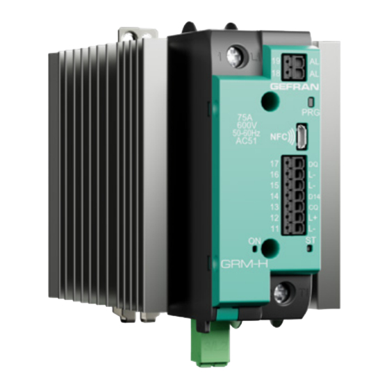
2.3. Panel fixing 2.4. Front view 819XX_MAN_GRM-H_11-2022_ENG_pag. 9... -
Page 10: Pinout
2.5. Pinout 2.5.1. Analog control VERSION WITH ANALOG INPUT Analog ouput 0-20 / 4-20 mA Fuse 0-5 / 0-10 V Fuse Controller Load Fuse Fuse: fast fuse, see fuse table Fuse gg: see fuse section * Input/ output configurable functions Connection for single phase load Power terminals Ref. -
Page 11: Io-Link Control
2.6.1. IO-Link control VERSION WITH IO-LINK INPUT Fuse Fuse Load Fuse Fuse: fast fuse, see fuse table Fuse gg: see fuse section * Input/ output configurable functions Connection for single phase load Power terminals Ref. Description Notes 1/L1 Line Connection 2/T1 Load Connection 3/L2... -
Page 12: Load Wiring
2.7. Load wiring Notes - See parameters dedicated at input and output signal configuration (parameters io.13 and io.17 for - To improve immunity to EMC disturbances, it is Master-Slave). recommended to connect the A2 pin of the power supply to earth. - With potentiometer input connect Always A- to A2 GRM WITH AN OPTION WITH MONOPHASE RESISTIVE LOAD 1/L1... - Page 13 GRM WITH IO-LINK OPTION WITH MONOPHASE RESISTIVE LOAD 1/L1 SLAVE SSR* DI AUX* 2/T1 24Vdc 3/L2 LINK MASTER LOAD FUSE IO-LINK - FIRING MODE: ZC, BF, HSC, PA - HB DIAGNOSTIC AVAILABLE: FUSE TOTAL and PARTIAL LOAD failure FUSE : fast fuse, see fuse table FUSE GG : see Fuse section * INPUT/ OUTPUT CONFIGURABLE FUNCTIONS...
- Page 14 GRM MASTER + 1 GRS SLAVE FOR STAR/DELTA SUPPLY 1/L1 1/L1 CONTROLLER ANALOG OUPUT 0-20 / 4-20 mA 0-5 / 0-10 V Master device could be also controlled by IO-Link 4/A1 3/A2 CLOSED STAR DELTA 2/T1 2/T1 3/L2 FUSE FUSE - GRM: MASTER FUSE : fast fuse, see fuse table - GRS: SLAVE...
- Page 15 GRM MASTER + 2 GRS (GRS WITHOUT DIAGNOSTIC) SLAVE FOR STAR/DELTA SUPPLY 1/L1 1/L1 1/L1 CONTROLLER ANALOG OUPUT 0-20 / 4-20 mA 0-5 / 0-10 V Master device could be also controlled by IO-Link 4/A1 4/A1 3/A2 3/A2 CLOSED STAR DELTA 2/T1 2/T1...
- Page 16 GRM MASTER + 2 GRP SLAVE FOR STAR/DELTA SUPPLY 1/L1 1/L1 1/L1 CONTROLLER ANALOG OUPUT 0-20 / 4-20 mA 0-5 / 0-10 V Master device could be also controlled by IO-Link CLOSED STAR DELTA 2/T1 2/T1 2/T1 3/L2 FUSE - GRM 1: MASTER - GRP 2/3: SLAVE - FIRING MODE: ZC, BF - CLOSED DELTA and STAR: TOTAL AND PARTIAL...
- Page 17 GRM MASTER + 2 GRP SLAVE FOR STAR WITH NEUTRAL LOAD SUPPLY 1/L1 1/L1 1/L1 CONTROLLER ANALOG OUPUT 0-20 / 4-20 mA 0-5 / 0-10 V Master device could be also controlled by IO-Link 2/T1 2/T1 2/T1 STAR WITH NEUTRAL 3/L2 FUSE - GRM: MASTER...
- Page 18 GRM MASTER + 2 GRS SLAVE FOR OPEN DELTA LOAD SUPPLY 1/L1 1/L1 1/L1 CONTROLLER 8/AL 8/AL ANALOG OUPUT 7/AL 7/AL 0-20 / 4-20 mA 6/A2 6/A2 0-5 / 0-10 V 5/A1 Master device could be also 5/A1 4/US controlled by IO-Link 4/US 3/A2 3/A2...
- Page 19 3 GRM FOR OPEN DELTA LOAD SUPPLY 1/L1 1/L1 1/L1 CONTROLLER ANALOG OUPUT 0-20 / 4-20 mA SERIAL 0-5 / 0-10 V PARALLEL 2/T1 2/T1 2/T1 3/L2 3/L2 3/L2 GRM 1 LOAD 1 FUSE FUSE FUSE OPEN DELTA FUSE FUSE FUSE - GRM: 1,2,3: INDEPENDENT - FIRING MODE: ZC, BF, HSC, PA...
-
Page 20: Terminal And Conductor Table
2.8. Terminal and conductor table POWER TERMINALS Rigid/flexible / ferrule conductor cross section 120A Size 10,5 x 10,7 mm Contact area (WxD) screw type 13 mm Stripping length 1 x 2.5 mm 1 x 6 mm 1 x 10 mm 1 x 16 mm 1 x 25 mm 1 x 50 mm... -
Page 21: Fan Maintenance
2.9. Fan maintenance Caution: make sure that the arrow showing the direction of the air flow on the fan is pointing toward the dissipater REMOVE REMOVE CONNECTOR CONNECTOR REMOVE SCREW REMOVE SCREW CONNECTOR ON PCB CONNECT FAN-CABLES FIX NEW FAN FIX NEW FAN BY SCREW 2 BY SCREW 2... -
Page 22: Configuration
Data is exchanged by placing the and the GRM-H continues to work with the original smartphone NFC antennas a few mm from the Gefran recipe. If the checks are passed, the device loads the NFC Dongle (see table "7.5. Accessoires" on page recipe transmitted from the NFC write memory to the 93). -
Page 23: Configuration Software And Real-Time Checks
The GRM-H device can be fully configured, controlled and monitored via the IO-Link point-to-point communication protocol. The IODD files characteristic of the device can be downloaded from www.gefran. com, from the page dedicated to the GRM-H device. For details of all parameters and commands available in IO-Link, refer to section "6. -
Page 24: Key
3.1.4. Some basic settings can be edited or the load current xxx-AN-xxxxxx models) calibration phase started using the key and the LEDs • Minimum number of cycles of the Burst Firing mode on the front of the object. The basic settings are: (see parameter bF.Cy) (only if hd.5 = BF). - Page 25 In HB (Heater Break) alarm conditions with memory or PF RED LED pressed (Power Fault) with memory or with SHORT_CIRCUIT_ CURRENT alarm active, by pressing the key according to HB or PF ALARM MEMORY the flow illustrated below, it is possible to reset the HB or PF OPERATION WITH RESET SETTING HB or PF ALARM...
-
Page 26: Led
The ST LED shows the following states which are shown in order of priority (the first in the table has the highest priority): GREEN BLUE STATO STEADY FLASHES STEADY FLASHES STEADY FLASHES Key management (see chapter Configuration Device configuration ”3.1.4. Key” on page 24) ■... -
Page 27: Parameter Descriptions
PARAMETER DESCRIPTIONS 5.1. Inputs 5.1.1. Analog input Available only for GRM-H-x-x-x-AN-x-x-x-x-x-x model Settings 5.1.1.1. Analog input type Acronym App / GF_eXpress menu Attribute Retentive U.M. Default Description Inputs Analog input ■ The parameter sets the type of analog input. Options: 0 Input disabled 1 0...10V... -
Page 28: Analog Input Correction Offset
5.1.1.4. Analog input correction offset Acronym App / GF_eXpress menu Attribute Retentive U.M. Default Description Inputs Analog input s.p. ■ The parameter sets the analog input correction offset. It can be used to recalibrate the analog input or set a minimum power. Example, if oFS=10.0, when the 0..10V input is at 0V the power supplied will be 10.0%, at 9V it will be 100.0%. -
Page 29: Analog Input Status
5.1.1.8. Analog input status Acronym App / GF_eXpress menu Attribute Retentive U.M. Default Description Status Analog input self-diagnosis status Value Meaning No error Error (*) (*) The input is in error when a 4 ... 20 mA input is used and the current is less than 2 mA: the Error status is generated and the power defined in FA.P is supplied. -
Page 30: Current Reading Scale Maximum Limit
5.1.2.4. Current reading scale maximum limit Acronym App / GF_eXpress menu Attribute Retentive U.M. Default Description H.tA Inputs CT input ■ Current reading scale maximum limit. Model Default 15 A 25.0 25 A 25I A 40.0 30 A 30I A 50.0 40 A 60.0... -
Page 31: Line Voltage Value
5.1.3. Line voltage value Settings 5.1.3.1. Voltage reading correction offset Acronym App / GF_eXpress menu Attribute Retentive U.M. Default Description o.tV Inputs VT line input ■ Voltage reading correction offset. min...max: -99.9 ...99.9 V 5.1.3.2. Voltage reading low pass digital filter Acronym App / GF_eXpress menu Attribute Retentive... -
Page 32: Voltage Reading Input Real-Time Value
5.1.3.5. Voltage reading input real-time value Acronym App / GF_eXpress menu Attribute Retentive U.M. Default Description Expert Status Voltage I.tV Voltage reading real-time value. 5.1.3.6. Voltage reading input value Acronym App / GF_eXpress menu Attribute Retentive U.M. Default Description I.tVF Status... -
Page 33: Values On Load
5.1.4. Values on load Status 5.1.4.1. RMS load current Acronym App / GF_eXpress menu Attribute Retentive U.M. Default Description Status Ld.A RMS load current. 5.1.4.2. Load voltage Acronym App / GF_eXpress menu Attribute Retentive U.M. Default Description Status Ld.V Load voltage. 5.1.4.3. -
Page 34: Consumed Energy Meter 2
5.1.4.6. Consumed energy meter 2 Acronym App / GF_eXpress menu Attribute Retentive U.M. Default Description Status Ld.E2 ■ Value of the E2 energy consumed since the first start-up or since the last meter reset. Commands 5.1.4.7. Energy meter reset Acronym App / GF_eXpress menu Attribute Retentive U.M. -
Page 35: Alarms
5.2. Alarms 100 s (output ON for 6 s each cycle); and if the 5.2.1. HB (Heat Break) Alarm delivered power is 100%, the alarm will trigger after This type of alarm makes it possible to identify 60 s. breakage (partial or total) or interruption of the load through the measurement of the current delivered, If the alarm goes off during this interval, the time sum obtained by means of an integrated current sensor. -
Page 36: Functional Diagram
5.2.1.2. Functional diagram Alarm setpoint Function of Hb.tr HB alarm State of alarm HB and time for I.onF activation of HB alarm (Hb.F, Hb.t) NOTE: (Hb.F, Hb.t) the value of setpoint Hb.tr for the HB alarm is calculated in two different ways, depending on the selected function mode: if ZC, BF, HSC mode : ........ -
Page 37: Enabling Hb Alarm
Settings 5.2.1.3. Enabling HB alarm Acronym App / GF_eXpress menu Attribute Retentive U.M. Default Description Alarms HB alarm Hb.E ■ Enabling HB alarm. Options: 0 Disabled 1 Enabled 5.2.1.4. Enable memory for HB alarm Acronym App / GF_eXpress menu Attribute Retentive U.M. -
Page 38: Delay Time For Hb Alarm Activation
5.2.1.6. Delay time for HB alarm activation Acronym App / GF_eXpress menu Attribute Retentive U.M. Default Description Alarms HB Alarm Hb.t ■ Delay time for HB alarm activation The value must be greater than the power output cycle time. min...max: 0 ...999 s 5.2.1.7. -
Page 39: Alarm States
5.2.1.10. Alarm states Acronym App / GF_eXpress menu Attribute Retentive U.M. Default Description Expert Status Diagnostics STATUS2 Alarm states connected to the HB alarm. Meaning AL.HB or Power Fault AL.HB 5.2.1.11. Detailed HB alarm status Acronym App / GF_eXpress menu Attribute Retentive U.M. -
Page 40: Hb Alarm Threshold Percentage
5.2.1.13. HB alarm threshold percentage Acronym App / GF_eXpress menu Attribute Retentive U.M. Default Description Alarms HB Alarm 90.0 Hb.P ■ HB alarm threshold percentage of the current read in HB calibration. Recommended values for the number of equal parallel loads controlled by a single SSR: no. -
Page 41: Current Reading In Hb Calibration For Ir Lamps
5.2.1.17. Current reading in HB calibration for IR lamps Acronym App / GF_eXpress menu Attribute Retentive U.M. Default Description Ir.tA.0 Alarms HB Alarm ■ Ir.tA.1 Alarms HB Alarm ■ Ir.tA.2 Alarms HB Alarm ■ Ir.tA.3 Alarms HB Alarm ■... -
Page 42: Max Hb Ir Calibration Power
5.2.1.19. Max HB IR Calibration power Acronym App / GF_eXpress menu Attribute Retentive U.M. Default Description Hn.Pm Alarms HB Alarm 100.0 ■ Maximum power during HB calibration (for IR lamps only) Commands 5.2.1.20. Alarm reset Acronym App / GF_eXpress menu Attribute Retentive U.M. -
Page 43: Enable Memory For Power Fault Alarms
5.2.2.2. Enable memory for Power Fault alarms Acronym App / GF_eXpress menu Attribute Retentive U.M. Default Description Alarms PF alarms PF.m ■ Enable memory for Power Fault alarm: after the causes that triggered the PF alarms have disappeared, the alarms remain on until reset by key, serial line or IO-Link. Options: 0 Disabled 1 Enabled... -
Page 44: Alarm States
Status 5.2.2.5. Alarm states Acronym App / GF_eXpress menu Attribute Retentive U.M. Default Description Expert Status Diagnostic STATUS2 Alarm status connected to Power Fault and HB. Meaning Heater Break or Power Fault alarms Heater Break alarm Power Fault alarms (OR of 3,4,5) SSR_SHORT NO_VOLTAGE NO_CURRENT... -
Page 45: Thermal Protection Alarm
This condition could be caused by improper 5.2.3. Thermal protection alarm ventilation of the electrical panel, obstruction of the ventilation slots or blocked cooling fan (if installed). The device is equipped with a temperature sensor for the internal heat sink; With the over_heat alarm on, the control disables The heatsink temperature value is contained in the control outputs... -
Page 46: Short_Circuit_Current Alarm
The number of trips to switch off the overcurrent 5.2.4. SHORT_CIRCUIT_CURRENT alarm protection device is shown in FO.c1 and FO.c2. FO.c1 and FO.c2 are updated 30 s after a successful The SHORT_CIRCUIT_CURRENT alarm trips when restart. the peak current on the load exceeds the maximum The FO.c1 count can be reset by command via serial valueallowed during the softstart ramp or at first or IO-Link. -
Page 47: Inputs/Outputs
5.3. Inputs/Outputs 5.2.4.2. Function for pin13 input/output Acronym App / GF_eXpress menu Attribute Retentive U.M. Default Description Inputs/Outputs io.13 ■ Function for input or reference for output relative to pin13 (for GRM-Hxx-AN-xx-xx-xxx models only). In the case of potentiometer input, digital input 1 operations have no effect and the terminal on the connector is used as the potentiometer power supply output. -
Page 48: Pin 13 Input/Output Type
5.2.4.3. Pin 13 input/output type Acronym App / GF_eXpress menu Attribute Retentive U.M. Default Description Inputs/Outputs io.13.t ■ Pin 13 input/output type (for GRM-H-x-x-AN-x-x-x-x-x-x-x models only). Options: Direct (if output, normally off) Reverse (if output, normally on) 5.2.4.4. Function for pin14 input Acronym App / GF_eXpress menu Attribute Retentive... -
Page 49: Function For Pin17 Input/Output
5.2.4.6. Function for pin17 input/output Acronym App / GF_eXpress menu Attribute Retentive U.M. Default Description Inputs/Outputs io.17 ■ Function for input or reference for output relative to pin17. Options: Value Function Notes I/O disabled In - HB calibration Rising edge In –... -
Page 50: Function For Pin19 Output
5.2.4.8. Function for pin19 output Acronym App / GF_eXpress menu Attribute Retentive U.M. Default Description Inputs/Outputs o.19 ■ Reference for output relative to pin19. Options: Value Function Output disabled HB or PF alarms HB alarm PF alarms SSR overtemperature HB or PF alarms or SSR overtemperature HB alarm or SSR overtemperature PF alarms or SSR overtemperature Dryout status... -
Page 51: Digital Filter For Pwm Input
5.2.4.11. Digital filter for PWM input Acronym App / GF_eXpress menu Attribute Retentive U.M. Default Description Inputs/Outputs PWM.F ■ The parameter sets the time of the low pass filter on the digital PWM input signal. min...max: 0.0 20.0 s Status 5.2.4.12. -
Page 52: Counters
5.4. Counters 5.4.4.1. HB alarms counter 1 Acronym App / GF_eXpress menu Attribute Retentive U.M. Default Description Hb.c1 Counters ■ HB alarm event counter 1 (resettable). The counters are saved in the retentive memory every hour and when the line voltage is switched off. 5.4.4.2. -
Page 53: Overheat Event Counter 2
5.4.4.5. Overheat event counter 2 Acronym App / GF_eXpress menu Attribute Retentive U.M. Default Description Counters SH.c2 ■ SSR overheat event counter 2 (not resettable). The counters are saved in the retentive memory every hour and when the line voltage is switched off. 5.4.4.6. -
Page 54: Max Temperature Value Reached 1
5.4.4.10. Max temperature value reached 1 Acronym App / GF_eXpress menu Attribute Retentive U.M. Default Description Ntc.SSR.Max1 Expert Status Temperature °C ■ SSR temperature Maximum value 1 (resettable). The counters are saved in the retentive memory every hour and when the line voltage is switched off. 5.4.4.11. -
Page 55: Controls
5.5. Controls Once the dry.P power supply in PA mode has been 5.5.1. Dryout completed, it switches to the firing required by hd.5 For GRM-H-x-x-x-AC-x-x-x-x-x and GRM-Hx-x-x-FB-x- and to the power managed automatically/manually x-x-x-x models only. (without ramps). The drying phase ends with total execution for the set The DryOut function allows for load drying for a time dry.t time, but can be completed earlier with: dry.t at constant power dry.P delivered with PA firing... -
Page 56: Dryout Power
5.5.1.3. Dryout power Acronym App / GF_eXpress menu Attribute Retentive U.M. Default Description Controls dry.P ■ Power delivered during the Dryout phase. Attention! by setting a value > 0.0 the device provides power even in the absence of an Analog/ IO-LINK command min...max: 0.0 100.0 % Commands... -
Page 57: Communication Error Mode
5.5.1.7. Communication error mode Acronym App / GF_eXpress menu Attribute Retentive U.M. Default Description Controls C.E.m ■ Communication error mode The communication error in GRM-H-x-x-AN-x-x-x-x-x-x-x models is activated in the absence of the Modbus serial communication while in the GRM-H-x-x-I-x-x-x-x-x-x-x models in the absence of IO-Link communication Options: Disabled... -
Page 58: Ìinductive Load On
5.5.1.10. ìInductive load on Acronym App / GF_eXpress menu Attribute Retentive U.M. Default Description Controls ind.E ■ Inductive load control on.. Options: Disabled Enabled 5.5.1.11. Start modes Acronym App / GF_eXpress menu Attribute Retentive U.M. Default Description Controls P.On.t ■ This parameter sets the mode in which the device turns on when power is supplied. -
Page 59: Automatic/Manual Status
5.5.1.13. Automatic/Manual status Acronym App / GF_eXpress menu Attribute Retentive U.M. Default Description Controls STATUS Device status to set Automatic/Manual mode. Meaning ON (0) / OFF (1) Automatic (0) / Manual (1) When switched on, the following is set: - GRM-H-x-x-AN-x-x-x-x-x-x models: Automatic/Manual mode and software ON/OFF according to the P.On.t. -
Page 60: Power Control
5.6. Power control 5.6.1.1. Trigger modes “Zero crossing” mode In power control, the GRM-H provides the following This is a type of operation that eliminates EMC modes: interference. This mode manages load power through • modulation by varying the number of operating a series of ON operating cycles rather than OFF cycles with "zero crossing"... -
Page 61: Phase Angle (Pa) Mode
In the example shown in the figure, this parameter is with short / medium wave IR lamp loads, with such = 2. loads, to limit the steady state current with low power, it is useful to set a minimum power limit (e.g. Lo.P = HSC Half single cycle 10%) This mode corresponds to Burst Firing, which handles... -
Page 62: Softstart
5.6.1.3. Softstart conduction angle q stops at the corresponding value of the power to be transferred to the load. This type of start-up can be enabled in BF, PA and When the load shut-off time (settable) is exceeded, HSC mode (for versions with type AN or I control). the ramp is reactivated at the next power-on. -
Page 63: Trigger Modes
5.6.1.4. Trigger modes Acronym App / GF_eXpress menu Attribute Retentive U.M. Default Description Power Control hd.5 ■ Trigger mode selection. Options: FCT - Fixed Cycle Time BF - Burst Firing HSC - Half Single Cycle PA - Phase Angle 5.6.1.5. Minimum number of Burst Firing cycles Acronym App / GF_eXpress menu Attribute Retentive... -
Page 64: Soft Start Ramp Settings
Soft start ends before the defined time if the power 5.6.1. Soft start ramp settings reaches the corresponding required value set in manual control or calculated by the analog input. It can be enabled in either phase control or pulse train The soft start ramp triggers at first start up after mode and controls the conduction angle. -
Page 65: Enabling Softstart At Shutdown
5.6.1.4. Enabling softstart at shutdown Acronym App / GF_eXpress menu Attribute Retentive U.M. Default Description Power Control PS.S.E ■ Enabling softstart ramp at shutdown in ON/OFF software switching. Options: Shutdown ramp disabled Shutdown ramp enabled Status 5.6.1.5. Soft start ramp status Acronym App / GF_eXpress menu Attribute Retentive... -
Page 66: Maximum Peak Current During Softstart
5.6.2.2. Maximum peak current during softstart Acronym App / GF_eXpress menu Attribute Retentive U.M. Default Description Power Control A peak PS.tA ■ Maximum peak current during softstart min...max: 0.0 ... 999.9 A peak Model Default 15 A 35.0 25 A 25I A 55.0 30 A 30I A 70.0... -
Page 67: Maximum Rms Current At Steady State
5.6.2.4. Maximum RMS current at steady state Acronym App / GF_eXpress menu Attribute Retentive U.M. Default Description Power Control Fu.tA ■ The parameter sets the maximum limit of the RMS current at steady state. The default value depends on the size of the controller: min...max: 0.0 ... -
Page 68: Minimum Non-Conduction Time To Reactivate Triggering Delay
5.6.3.3. Minimum non-conduction time to reactivate triggering delay Acronym App / GF_eXpress menu Attribute Retentive U.M. Default Description Power Control dL.oF ■ Minimum non-conduction time to reactivate triggering delay. min...max: 0 ... 10000 ms 5.6.3.4. Minimum trigger power Acronym App / GF_eXpress menu Attribute Retentive U.M. -
Page 69: Feedback Mode
Power feedback (P) 5.6.4. Feedback mode This is used to keep the load power constant. It compensates possible variations in line voltage and/ The GRM-H offers the following possibilities to control or load impedance with respect to the rated power power through feedback: (value stored in riF.P, expressed in kWatts). -
Page 70: Enabling Feedback Mode
5.6.4.1. Enabling feedback mode Acronym App / GF_eXpress menu Attribute Retentive U.M. Default Description Power Control hd.6 ■ The parameter sets enabling of the feedback mode. Options: No feedback enabled V2 (quadratic voltage feedback) I2 (quadratic current feedback) P (power feedback) Z (impedance feedback) V (linear voltage feedback) I (linear current feedback) -
Page 71: Impedance Feedback Reference
5.6.4.5. Impedance feedback reference Acronym App / GF_eXpress menu Attribute Retentive U.M. Default Description Power Control 0.00 riF.I ■ The parameter sets the power feedback reference. min...max: 0.00 ...650.00 ohm 5.6.4.6. Feedback response speed Acronym App / GF_eXpress menu Attribute Retentive U.M. -
Page 72: Feedback Reference
Status 5.6.4.8. Feedback reference Acronym App / GF_eXpress menu Attribute Retentive U.M. Default Description Power Control Fb.r Feedback reference. The same value is reported in two distinct parameters Fb.r1 and Fbr2 represented with 1 or 2 decimal points Fb.r1 reference with 1 decimal point: for voltage or current feedback Fb.r2 reference with 2 decimal points: for power or impedance feedback 5.6.4.9. -
Page 73: Hardware And Software Information
Software version code. 5.7.4.2. Manufacturer identifier Acronym App / GF_eXpress menu Attribute Retentive U.M. Default Description Info 5000 mtmID Manufacturer - Trade Mark (Gefran). 5.7.4.3. Model identifier Acronym App / GF_eXpress menu Attribute Retentive U.M. Default Description deviceID Info Device ID (GRM). -
Page 74: Product Code (Fxxxxxx Order Code)
5.7.4.5. Product code (Fxxxxxx order code) Acronym App / GF_eXpress menu Attribute Retentive U.M. Default Description SAP.c Info ■ Product code (Fxxxxxx) Data in 32bit DWORD format (LSW + MSW) 5.7.4.6. Last modification user Acronym App / GF_eXpress menu Attribute Retentive U.M. -
Page 75: Hardware Card Recognition 1
Parameters that depend on the order code 5.7.4.8. Hardware card recognition 1 Acronym App / GF_eXpress menu Attribute Retentive U.M. Default Description C.Hd1 Info ■ Meaning Rated current 15A Rated current 25A Rated current 30A Rated current 40A Rated current 50A Rated current 60A Rated current 75A Rated current 90A... -
Page 76: Io-Link
IEC 61131-9 standard. and the interpretation of the data sent and exchanged Bothe power and digital communication are in the with the master. Please consult the Gefran website to same cable and connector. download the IODD files. -
Page 77: Control Mode
6.3. CONTROL MODE 6.3.1. IO-Link information Port class Baud rate COM2 (38.4 kbit/s) IO-Link version (1) Profile Common profile % power supplied: 2 bytes Ld.A (load current): 2 bytes Ld.V (load voltage): 2 bytes Ld.P (load power): 2 bytes Ld.I (load impedence): 2 bytes STATUS2: 2 bytes for diagnostics: STATUS2_NO_CURRENT: 1 bit... -
Page 78: Sio Mode And Io-Link Mode
6.3.2. SIO mode and IO-Link mode The static group supports both SIO mode and IO-Link Outputs) or as auxiliary input. mode. In SIO mode the device : In SIO mode the static group behaves like an - maintains control of the load, continuing to provide actuator: the status of the HB alarm is available on the last power set in IO-Link mode. -
Page 79: Setting Data
The device has the following Process Data Output mapping: Position Meaning Offset Length Output power Man.P (Percent value of manual 0…15 16 bit power to be supplied) (*) (*) The power value delivered by the static group GRM is updated starting from the PDO when the mode is OPERATE. - Page 80 • Default parameters - Identification Access Data Index Sub-index Name of the object Length Value (example) Description type 0x0010 0x00 VendorName GEFRAN spa String 0x0011 0x00 VendorText www.gefran.com String GRM-120-48-I-1-x- 0x0012 0x00 Max64 Full product description ProductName String x-x-x-x 0x0013...
- Page 81 • Errors and warnings in the Detailed Device Status Event Event Process data Event Description Device status Possible failure Reset mode code type value The temperature SSR temperature sensor Maintenance Requires intervention on the 0x8CA1 sensor does not give a Warning measured data broken...
- Page 82 Parametri del dispositivo - Indici primari • Access Name of the Data Value Range of Scale Index Sub-index Length Offset Unit Description object type (example) values factor Hb.E 0x0040 0x00 UInt16 1 (default) Enabling HB alarm R/W R/W 0, 1 Enable memory for 0x0041 0x00...
- Page 83 0x0064 0x00 Pin 14 digital input 0x0065 0x00 i.14.t R/W R/W UInt16 0 (default) 0, 1 pin type 0x0066 0x00 0x0067 0x00 dry.E R/W R/W UInt16 0 (default) 0, 1 Dryout enable dry.t 0x0068 0x00 R/W R/W UInt16 0.0 (default) 0.0…500.0 Dryout time 0x0069...
- Page 84 Voltage reading in 0x0081 0x00 Ir.tV.9 R/W R/W UInt16 0 (default) L.tV…H.tV HB calibration for IR lamps Phase softstart at 0x0082 0x00 PS.S.E R/W R/W UInt16 0 (default) 0, 1 ON/OFF software switching shutdown Peak current limiter 0x0083 0x00 Cu.S.E R/W R/W UInt16 0 (default)
- Page 85 Access Name of the Data Value Range of Scale Index Sub-index Length Offset Unit Description object type (example) values factor Name of the Range of Number of hours of Data Value Scale Index Sub-index RO RO RO Length Offset Unit object SSR operation values...
- Page 86 inta_counter RO RO RO 0x011A 0x00 0…65535 Uint16 IN_TV_ON_ 0x011B 0x00 0…65535 RO RO RO Uint16 DIAG IN_TV_OFF_ 0x011C 0x00 0.0…6553.5 RO RO RO Uint16 DIAG Voltage reading input 0x011D 0x00 I.tVF 0.0…6553.5 RO RO RO Uint16 value Pw.PA 0x011E 0x00 0.0…6553.5 RO RO RO...
- Page 87 STATUS 0x0156 0x00 0…65535 RO RO RO Uint16 Status PWM input 0x0157 0x00 In.PWM RO RO RO Uint16 0.0…100.0 value Power orrection Fu.c 0x0158 0x00 RO RO RO Int16 -100.0…100.0 for current limitation Power 0x0159 0x00 Fb.c RO RO RO Int16 -100.0…100.0 correction for...
-
Page 88: Technical Specifications
TECHNICAL SPECIFICATIONS 7.1. Technical specifications INPUTS Analogue command input (Versions with AN input type) Function Proportional power control signal Maximum Error 1% f.s. ± 1 scale point at an ambient temperature of 25°C/ 77°F Thermal shift <100 ppm/° C on f.s. Sampling time 10 ms 0-10V scale... - Page 89 Only for initial product configuration, via PC. Use a PC connected to the GRM, ONLY via the Functions with TTL serial cable Gefran adapter cable. The adapter powers the GRM. Cod. F060800 (PC with USB). Type Micro USB type B connector...
- Page 90 Installation category II, pollution degree 2 Installation requirements Maximum air temperature around the device 40°C / 104°F (for Temperature > 40°C / 104°F see derating curves) GRM-H 15, 25A, 25I 388 g / 16.69 Oz GRM-H 30A, 30I 388 g / 16.69 Oz GRM-H 40, 50A 388 g / 16.69 Oz...
-
Page 91: Derating Curves
7.2. Derating curves Rated current curves as a function of ambient temperature (minimum distance between GRM-H of 20mm). DERATING CURVES GRM-H 15 ÷ 30A GRM-H GRM-H GRM-H DERATING CURVES GRM-H 40 ÷ 60A GRM-H GRM-H GRM-H DERATING CURVES GRM-H 75 ÷ 120A... -
Page 92: Downgrade With Installation Distance
7.3. Downgrade with installation distance Rated current curves as a function of the horizontal distance between the GRM-Hs (ambient temperature 40 C / 104 F). DERATING CURVES GRM-H 15 ÷ 30A GRM-H GRM-H GRM-H DERATING CURVES GRM-H 40 ÷ 60A... -
Page 93: Extrarapid Fuses
EN 61439-1). 7.5. Accessoires Code Description F089025 1 NFC dongle for configuration via App + 1 Gefran keychain lanyard F089026 5 NFC dongles for configuration via App + 5 Gefran keychain lanyards F089027 10 NFC dongles for configuration via App F060800 Cable for programming with PC, USB-TTL 3 V with USB - microUSB connectors, length 1,8 m 7.6. -
Page 94: Order Code
7.7. Order code GRM-H - Rated current 15Aac 25Aac 25Aac I2t++ NFC Dongle accessory 30Aac Absent 30Aac I2t++ NFC Dongle included in the packaging 40Aac 50Aac 60Aac 75Aac 90Aac (Fan needed) 120Aac (Fan needed) Rated voltage 480Vac (60Vac…530Vac) for nominal current from 15A to 75A 600Vac (60Vac…660vac) No needed for 90/120A nominal current models... -
Page 95: Emc Standards
7.8. EMC standards EMC emissions AC semiconductor motor controllers and conductors for non- EN 60947-4-3 motor loads Class A Group 2 EN 60947-4-3 Emission enclosure Cl compliant in firing mode single cycle CISPR-11 and phase angle if external filter fitted EN 55011 EMC Immunity Generic standards, immunity standard for industrial... -
Page 96: Warnings
• do not clean the box with solvents derived from hydrocarbons (trichloroethylene, gasoline, etc.). Using such solvents will compromise the device’s mechanical reliability. Use a clean cloth moistened with ethyl alcohol or water to clean external parts in plastic. Service: GEFRAN has a service department. The warranty excludes defects caused by any use not conforming to these instructions. CERTIFICATIONS 8.1. - Page 97 GEFRAN spa via Sebina, 74 25050 Provaglio d’Iseo (BS) Italy Tel. +39 0309888.1 Fax +39 0309839063 info@gefran.com http://www.gefran.com...
Need help?
Do you have a question about the GRM-H 15 and is the answer not in the manual?
Questions and answers