Table of Contents
Advertisement
Quick Links
1
1.1
1.2
1.3
2
2.1
2.2
2.3
Recommendations for correct installation for
purposes of EMC
2.4
2.5
2.6
2.7
2.8
2.9
Replacing internal fuse (Optional)
2.10
2.11
3
3.1
3.2
Functions of LED indicators
3.3
Description Input/Output
To differentiate the type and importance of the information in this User Manual, graphic reference symbols are used to make such information
easier to interpret.
Indicates contents of sections, general instructions, notes, and
other points to which the reader's attention needs to be called.
Indicates a particularly delicate situation that could affect
the safety or correct operation of the controller, or an
instruction that MUST be followed to prevent hazards.
Indicates a risk to the user's safety due to high voltage at the
points indicated.
80962_MHW_GFW_12-2011_ENG
GFW adv
ADVANCED MODULAR POWER CONTROLLER
INDEX
2
4
12
GRAPHIC SYMBOLS
INSTALLATION AND
OPERATION MANUAL
Versione software: 1.0x
code 80962 - 12/2011 - ENG
3.4
Connector J1 outputs 5...10
3.5
Connector J2 power supply
3.6
Connector J2 digital input
3.7
Connector J3 auxiliary inputs 2...5
3.8
Connector J4 inputs 1...4
3.9
Connector J6: inputs PID
3.10
Description of dip-switches
3.11
Serial communication ports
3.12
Connection example: Power section
4
Installation of serial network
4.1
"AUTOBAUD SERIAL 1" sequence
4.2
"AUTONODE PORT 1" sequence
5
Technical Characteristics
5.1
Derating Curves Gfw (scr)
5.2
Derating Curves Gfw with electronic fuse (IGBT)
6
Technical-Commercial information
6.1
Order code
6.2
Accessories
6.3
Fuses / Fuseholders
Indicates a suggestion based on the experience of
GEFRAN's Technical Personnel that could be
especially useful under certain circumstances.
Indicates a reference to Detailed Technical
Documents available on the GEFRAN website
www.gefran.com.
40
42
47
1
Advertisement
Table of Contents

Related Manuals for gefran GFW adv


Summary of Contents for gefran GFW adv
-
Page 1: Table Of Contents
Indicates a suggestion based on the experience of Indicates contents of sections, general instructions, notes, and GEFRAN’s Technical Personnel that could be other points to which the reader’s attention needs to be called. especially useful under certain circumstances. -
Page 2: Preliminary Instructions
RMS current level at full power under control. In particular, this new line of Gefran solid state relays is the Thanks to sophisticated Hardware and Software solutions, you ideal solution for sectors demanding high performance and can precisely control different types of loads. -
Page 3: Preliminary Instructions
See paragraph ... “ Dimensions and mounting” before installing reliminary instruction the GFw on the machine/host system control panel. Read the following preliminary instructions before To configure the PC use the Sw Gefran GF-Express kit and the installing and using the GFX4-IR modular power relative connection cable. controller. -
Page 4: Installation And Connection
2 • INSTALLATION AND CONNECTION This section contains the instructions needed for ecommenDations for orrect nstallation correct installation of GFW modular power controller for PurPoses of on the machine/host system control panel and for 2.3.1 Instrument power supply correct connection of the power supply, inputs, • The power supply for the electronic instrumentation on the outputs and interfaces. - Page 5 GEFRAN S.p.A. assumes no liability for any • thermal power dissipation with limits on installation room temperature. damage to persons or property deriving from • requires exchange with external air or an air conditioner to tampering, from incorrect or improper use, or transfer dissipated power outside the panel. from any use not conforming to the • maximum limits of voltage and derived power of transients on characteristics of the controller and to the the line, for which the solid state power unit contains protective instructions in this User Manual.
- Page 6 INSULATION DIAGRAM 80962_MHW_GFW_12-2011_ENG...
-
Page 7: Dimensions
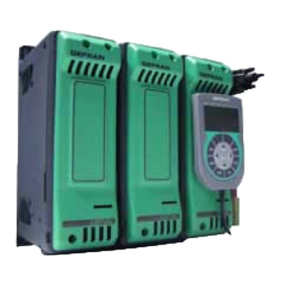
imensions Figure 1 GFW MASTER Lateral view Lateral view with keypad without keypad GFW DUAL-PHASE GFW THREE-PHASE (Master + 1 Expansion) (Master + 2 Expansions) 80962_MHW_GFW_12-2011_ENG... -
Page 8: Template Dimensions
emPlate Dimensions Figure 2 PANEL MOUNTING AND CUT-OUT DIMENSIONS GFw MASTER GFw DUAL-PHASE GFw THREE-PHASE Fastening may be done with (5MA). All dimensions are expressed in mm. nstallation Figure 3 Attention: respect the minimum distances shown in figure 3 to provide adequate air circulation. -
Page 9: General Description Gfw
eneral DescriPtion gfw Figure 4 “Line” Configuration terminals keypad connector Line / load voltage Output connector connector Supply connector Digital input connector 4 input TCAUX connector Internal fuse protection cover Configuration Dip Switch HB Key calibration Control input connector Address Rotary Switch input “Load”... -
Page 10: Cleaning/Checking Or Replacing The Fan
leaning checking or rePlacing the fan PERIODIC CLEANING Every 6-12 months (depending on the dust level of the installation) blow a compressed air jet downward through the upper rectangular cooling grilles (on the side opposite the fan). This will clean the internal heat dissipater and the cooling fan. IN CASE OF OVERHEAT ALARM If periodic cleaning does not eliminate the problem, do as follows: a Remove the fan support grille by detaching the two support tabs... - Page 11 ePlacing the nternal Ptional CUT OFF POWER BEFORE AND DURING FUSE SUBSTITUTION PROCEDURE - Undo the cover fastening screw (1) - Remove the cover following the movement indicated by the arrow (2) - In this way the fuse is discovered (3) - Loosen the two fastening nuts of fuse by means of tube-shaped spanner N.13 (GFw 40-150) - It is not necessary to remove the nuts as the fuse N.17 (GFw 200-250A) is slipped off its seat by turning it (4) and extracting it (5) as indicated by the arrows...
-
Page 12: Card Insertion For Fieldbus Interface
2.10 arD insertion for fielDbus interface DO AS FOLLOWS: a. Undo the screws 16 b. Turn slightly the points18 using a screwdriver c. Remove the cover 17 d. Place the interface card 19 in the connectors prepared on card 21 e. -
Page 13: Connection Of Expansion Modules
2.11 onnection of exPansion moDules for biPhase or triPhase configuration CARRY OUT THE FOLLOWING STEPS: a. Remove the master module side cover by undoing the fastening screws b Connect the flat cables supplied with the expansions to CPU card by inserting them into the appropriate connectors. c. -
Page 14: Electrical Connections
3 • ELECTRICAL CONNECTIONS ower connections GFW 40-250A RECOMMENDED WIRE GAUGES TIGHTENING / GFW CURRENT LEVEL TERMINAL WIRE GAUGE TERMINAL TYPE TOOL TORQUE wire stripped for 25 mm or with 4 ... 5 Nm / Flat-head 1/L1, 2/T1 10 mm² crimped pre-insulated terminal tube screwdriver CEMBRE PKC1018... - Page 15 nPut utPut onnections escriPtion nPut utPut Figure 11 Top View Protection (Ref. V_load) 4 / T2 3 / L2 (Ref. V_line) J 10 Line / load voltage connector 1 / L1 “Line” Connection 1 / L1 “Line” Connection COM (OUT 5 - 8) KB-ADL OUT 5 keypad...
- Page 16 5...10 onnector outPuts If auxiliary outputs (O5...O8), are present, connector J1a becomes J1. Figure 12 Connector J1 Table 6 0,2 - 2,5mm 24-14AWG 0,25 - 2,5mm 23-14AWG Outputs 5...8 logic/continuous type Logic outputs 18...36Vdc, max 20mA Continuous outputs: voltage (default) 0/2...10V, max 25mA current 0/4...20mA, max 500Ω...
- Page 17 when using the continuous “C” output option, voltage or current is set using jumper links on the board (Figure 14 refers). Figure 14 Connection for logic/continuous utputs 80962_MHW_GFW_12-2011_ENG...
- Page 18 Outputs 5...8 triac type Triac outputs Vac = 24...230Vac, max 1A Figure 15 Connection scheme for triac outputs Com 5√8 Table 8 Name Decription Outputs common Com 5-8 Output 5 Output 6 Output 7 Output 8 Outputs 5...8 relay type Outputs Out 5...8 relay Ir = 3A max, NO V = 250V/30Vdc cos = 1;...
- Page 19 onnector Power suPPly Figure 18 Table 11 0,2 - 2,5mm 24-14AWG 0,25 - 2,5mm 23-14AWG Figure 19 Table 12 Name Decription +24 Vdc 24V Supply EARTH Ground EMC onnector Digital inPut Figure 20 Table 13 0,14 - 0,5mm 28-20AWG 0,25 - 0,5mm 23-20AWG Figure 21 Connection scheme for digital inputs...
- Page 20 5...8 onnector auxiliary inPuts Figure 22 Table 15 0,14 - 0,5mm 28-20AWG 0,25 - 0,5mm 23-20AWG Figure 23 Auxiliary inputs I5 - I8 (60mV/TC) Table 16 Name Description Auxiliary input 2 Auxiliary input 3 Auxiliary input 4 Auxiliary input 5 80962_MHW_GFW_12-2011_ENG...
- Page 21 onnector analog inPut control Figure 24 Table 17 0,2 - 2,5mm 24-14AWG 0,25 - 2,5mm 23-14AWG Figure 25 Connection scheme Table 18 Name Description +5V_Out Supply output 5V potentiometer Control voltage Input SHUNT Shunt for input mA GND control signal 80962_MHW_GFW_12-2011_ENG...
- Page 22 J6: PiD I onnctor nput Figura 26 Table 19 0,2 - 2,5mm 24-14AWG 0,25 - 2,5mm 23-14AWG Figure 27 Connection scheme for 60mV TC/linear input Figure 28 Connection scheme for Pt100 input Table 20 Name Description EARTH EMC earth (for shielded cable) Negative Input Positive Input TC and RTD 3rd wire RTD, Positive IN mA,...
- Page 23 3.10 Description of dip-switches Figure 30 Table 22 Description dip-switches Connection type: (see table 23) Connection type: (see table 23) Connection type: (see table 23) Connection type: (see table 23) OFF = resistive load ON = inductive load (transformer primary control) ON = reset factory configuration ON = Geflex simulation function...
- Page 24 3.11 erial communication Ports Port1 (local bus): Modbus serial interface – connectors S1, S2. Figure 31 Port 2 (Fieldbus optiobal board) Port 1 (Fieldbus optiobal board) Table 24 Connector S1/S2 Nr. Pin Name Description Note RJ10 4-4 pin GND1 (**) (*) Insert the RS485 line termination in the last device Data reception/transmission (A+) Tx/Rx+...
- Page 25 Port2 (fieldbus): connectors S4, S5 MODBUS RTU/MODBUS RTU Figure 32 Port2: Fieldbus Modbus RTU/Modbus RTU interface Connector S5 Connector S4 Line termination (*) Table 25 Connector S4/S5 Nr. Pin Name Description Note RJ10 4-4 pin GND1 (**) (*) Insert the line termination in the last device on the Modbus line.
- Page 26 Port2 (fieldbus): connectors S4, S5 MODBUS RTU/Profibus DP Figure 33 Port2: Fieldbus Modbus RTU/Profibus DP interface S5 female connector S4 female connector Yellow Led Red Led Green Led Table 26 Connector S4 Nr. Pin Name Description Note RJ10 4-4 pin GND1 (**) (**) Connect the GND signal between Modbus devices with a...
- Page 27 Port2 (fieldbus): connectors S4, S5 MODBUS RTU/CANopen or EUROMAP 66 Figure 34 Port2: Fieldbus Modbus RTU/CANOpen interface or EUROMAP 66 S5 male connector S4 female connector Red Led Green Led Table 28 Connector S4 Nr. Pin Name Description Note RJ10 4-4 pin GND1 (**) (**) Connect the GND signal between Modbus devices with a...
- Page 28 Port2 (fieldbus): connectors S4, S5 MODBUS RTU/DeviceNet Figure 35 Port2: Fieldbus Modbus RTU/DeviceNet interface S5 male connector S4 female connector Red Led Green Led Table 30 Connector S4 Nr. Pin Name Description Note RJ10 4-4 pin GND1 (**) (**) Connect the GND signal between Modbus devices with a Rx/Tx+ Data reception/transmission (A+) line distance >...
- Page 29 Port2 (fieldbus): connectors S4, S5 Modbus RTU / Ethernet Modbus TCP Figure 36 Port2: Modbus RTU / Ethernet Modbus TCP interface S5 female connector S4 female connector Yellow Led Green Led Table 32 Connector S4 Nr. Pin Name Description Note RJ10 4-4 pin GND1 (**) (**) Connect the GND signal...
- Page 30 Port2 (fieldbus): connectors S4, S5 Modbus RTU / Ethernet IP Figure 37 Port2: Modbus RTU / Ethernet IP interface Green led Packet activity Yellow led Link integrity S4 female connector S5 female connector Table 34 Connector S4 Nr. Pin Name Description Note RJ10 4-4 pin...
- Page 31 Port2 (fieldbus): connectors S4, S5 Modbus RTU / EtherCAT Figure 38 Port2: Modbus RTU / EtherCAT Green led Packet activity Yellow led Link integrity S4 female connector S5 female connector Table 36 Connector S4 Nr. Pin Name Description Note RJ10 4-4 pin GND1 (**) (**) Connect the GND signal between Modbus devices with a...
- Page 32 3.12 onnection examPle ower section Figura 39 GFW connection example for 1 single-phase load. (*) Only required with Vload measurement input option. V= phase voltage (line - neutral) GFW Master - Dip switch configuration P = power of each single-phase load - FIRING MODE: ZC, BF, HSC, PA Dip 1 Dip 2 Dip 3...
- Page 33 Figure 41 Sample GFW biphase connection for a triphase load GFW Master - Dip switch configuration Dip 1 Dip 2 Dip 3 Dip 4 Dip 5 - FIRING MODE: ZC, BF V = line voltage P = total power - HB DIAGNOSTIC AVAILABLE: Id = load current Total load failure (partial only for if resistive load cosj=1...
- Page 34 Figura 42 GFW connection example for 1 3-phase closed delta load (*) Only required with Vload measurement input option. V= line voltage P = total power Id = load current if resistive load cosj=1 GFW Master - Dip switch configuration - FIRING MODE: ZC, BF, PA Dip 1 Dip 2 Dip 3 Dip 4 Dip 5...
- Page 35 Figura 44 GFW connection example for 1 3-phase star load without neutral (*) Only required with Vload measurement input option. V= line voltage Vd= load voltage GFW Master - Dip switch configuration P = total power - FIRING MODE: ZC, BF, PA Id = load current Dip 1 Dip 2 Dip 3 Dip 4 Dip 5...
- Page 36 Figue 46 G FW connection example for 1 3-phase star load with neutral (*) Only required with Vload measurement input option. V= line voltage Vd= load voltage GFW Master - Dip switch configuration - FIRING MODE: ZC, BF, HSC, PA P = total power Dip 1 Dip 2 Dip 3 Dip 4 Dip 5 - HB DIAGNOSTIC AVAILABLE:...
- Page 37 Figure 48 GFW connection example for 3 independent loads in open delta, 3-phase line without neutral (*) Only required with Vload measurement input option. V= line voltage GFW Master - Dip switch configuration - FIRING MODE: ZC, BF, HSC, PA P = power of each single-phase load Dip 1 Dip 2 Dip 3 Dip 4 Dip 5 Id = load current - HB DIAGNOSTIC AVAILABLE:...
- Page 38 Figure 50 Example of GFW-2PH for 2 indipendent single phase loads It is possible to connect two single-phase loads also to different line voltages, between line to line or line to neutral It is possible to manage different power values for each one of the two loads. V= line voltage P = power of each single-phase load Id = load current if resistive load cosj=1...
- Page 39 NOTES: USE WITH INDUCTIVE LOADS AND TRANSFORMERS a) when the GFw is working it is not allowed to open neither the connection between GFw and the transformer nor the connection between the transformer and the load b) The maximum current controllable by the device is less than the product’s rated value (see technical data). c) In ZC and BF trigger mode, use the Delay-triggering function to limit peak magnetization current.
- Page 40 Figure 52 parameter defines the minimum number of conduction cycles settable from 1 to 10. In the following example, the parameter = 2. HSC - Half single cycle This mode corresponds to Burst Firing that includes ON and OFF half-cycles. NB: This mode is NOT allowed with inductive loads (transformers).
- Page 41 ADDITIONAL FUNCTIONS Softstart This type of start can be enabled either in phase control or pulse train mode and in zero-crossing mode (ZC, BF, HSC). In phase control, the increment of conduction angle q stops at the corresponding value of the power to be transferred to the load.
- Page 42 DT - “Delay triggering” (for ZC, BF control modes only) Settable from 0° to 90°. Useful for inductive loads (transformer primaries) to prevent current peak that in certain cases could trip the high-speed fuses that protect the SCRs. Figure 57 Transient with Transient without Over-Current...
- Page 43 4 • INSTALLATION OF “MODBUS” SERIAL NETWORK A network typically has a Master that “manages” communication by means of “commands,” and Slaves that carry out these commands. GFw modules is considered Slaves to the network master, which is usually a supervision terminal or a PLC. It is positively identified by means of a node address (ID) set on rotary switches (tens + units).
- Page 44 4.1 “AUTOBAUD SERIAL 1” sequence Function Adapt the serial communication speed and parity of the GFw modules to the connected supervision terminal or PLC. Green LED L1 “STATUS” mentioned in the procedure can vary its behavior based on parameter Ld.1, which is set to a default value of 16. Procedure 1) Connect the serial cables for all modules on the network to serial 1 and to the supervision terminal.
- Page 45 5 • TECHNICAL CHARACTERISTICS INPUTS INA Analogic control inputs Function Acquisition of % value for power control Linear: 0,…,5Vdc, Ri>100Kohm Voltage Linear: 0,…,10Vdc, Ri>100Kohm Current Linear: 0/4…20mA, Ri =125ohm Potentiometric 1, ..., 10Kohm, max 10mA from 5Vdc power GFw IN1 Analog process inputs (option) Function Acquisition of process variable Max.
- Page 46 0/2…10V (default), max 25mA short circuit protection Continuous 0/4…20mA, max. load 500ohm isolation 500V Logic 24Vdc, > 18V a 20mA Triac 230V/ max 4A AC51 (1A for each channel) OUT9, OUT10 alarm Function Function Configurable (default alarms) Relay Contact NO 5A, 250V/30Vdc cosφ =1 COMMUNICATIONS PORTS PORT KB-ADL Serial comunication for KB-ADL terminal to display parameter...
- Page 47 GFW 40 (SCR) Nominal current 40Arms @40°C in continuous service Non-repetitive overcurrent t=10ms: 1400A I²t per fusione: 10000A²s GFW 60 (SCR) Nominal current 60Arms @40°C in continuous service Non-repetitive overcurrent t=10ms: 1500A I²t for blowout: 12000A²s GFW 100 (SCR) Nominal current 100Arms @40°C in continuous service Non-repetitive overcurrent t=10ms: 1900A I²t for blowout: 18000A²s GFW 150 (SCR)
- Page 48 OPTIONS - Timed Soft-Start firing ramp, with or without peak current control - Soft-Start firing ramp, specific for infrared lamps Options - Timed shut-off ramp - Limitation of RMS current in load - 0-90° Delay-Triggering for firing inductive loads in ZC and BF mode - SCR in short circuit (presence of current with OFF control) - No linear voltage...
- Page 49 erating urves Figure 59 GFw 40 / 60 / 100 GFw 150 / 200 / 250 with electronic fuse (IGBT) erating urves Figure 60 GFw with electronic fuse 80962_MHW_GFW_12-2011_ENG...
- Page 50 6 • Commercial Information rDer coDe GFW - Mono-phase FIELDBUS Port 2 opz. Model Absent Master with CPU Modbus RTU Nominal Current Profibus DP 40Ampere CANopen 60Ampere Euromap 66 100Ampere DeviceNet 150Ampere Ethernet Modbus TCP 200Ampere Ethernet IP 250Ampere EtherCAT Nominal Voltage Fuses 480Vac Absent...
- Page 51 6 • Commercial Information rDer coDe GFW - Dual-Phase FIELDBUS Port 2 opz. Model 1 module master (CPU) + Absent 1 expansion module Modbus RTU Profibus DP CANopen Nominal Current Euromap 66 40Ampere DeviceNet 60Ampere Ethernet Modbus TCP 100Ampere Ethernet IP 150Ampere EtherCAT 200Ampere...
- Page 52 6 • Commercial Information rDer coDe GFW - Three-phase FIELDBUS Port 2 opz. Model 1 module master (CPU) + Absent 2 expansion modules Modbus RTU Profibus DP CANopen Nominal Current Euromap 66 40Ampere DeviceNet 60Ampere Ethernet Modbus TCP 100Ampere Ethernet IP 150Ampere EtherCAT 200Ampere...
- Page 53 ccessories CONFIGURATION KIT Configuration/supervision kit for GFW by means of PC with RS232 serial line (Windows envi- KIT PC RS232 / RS 485 ronment). Lets you read or write all of the parameters of a single GFw A single software for all models • Easy and rapid configuration • Saving and management of parameter recipes • On-line trend and saving of historical data Component Kit: - Connection cable PC RS232 <----> GFW RS485 port - Serial line converter - CD SW GF Express installation ORDERING CODE...
Need help?
Do you have a question about the GFW adv and is the answer not in the manual?
Questions and answers