Table of Contents
Advertisement
LIST OF ATTACHMENTS
This document supplements the following manuals:
- Instructions and warnings for GFXTERMO4
- Instructions and warnings for GFX4
80397M_MSW_GFX4-GFXTERMO4_08-2018_ENG
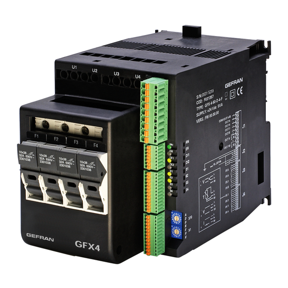
GFX4 / GFXTERMO4
4-ZONE MODULAR POWER CONTROLLER
CONFIGURATION AND
PROGRAMMING MANUAL
Software version: 2.1x
code: 80397M - 08-2018 - ENGLISH
ATTENTION!
This manual is an integral part of the product,
and must always be available to operators.
This manual must always accompany the
product, including if it is transferred to another user.
Installation and/or maintenance workers MUST
read this manual and scrupulously follow all of the
instructions in it and in its attachments. GEFRAN will
not be liable for damage to persons and/or property, or
to the product itself, if the following terms and condi-
tions are disregarded.
The Customer is obligated to respect trade se-
crets. Therefore, this manual and its attachments may
not be tampered with, changed, reproduced, or trans-
ferred to third parties without GEFRAN's authorization.
1
Advertisement
Table of Contents

Related Manuals for gefran GFXTERMO4


Summarization of Contents
Gefran GFX4/GFXTERMO4 Configuration Manual
List of Attachments
Lists supplementary manuals for the GFX4/GFXTERMO4.
Important Attention Note
Highlights the importance of the manual and proper usage.
Introduction to the Power Controller
Field of Use for the Power Controller
Describes the intended applications and general use of the modular power controller.
Personnel Characteristics and Responsibilities
Specifies the required technical knowledge and training for operators.
Input Configuration and Parameters
Main Input Settings
Details on probe type, scale limits, decimal point, and offset for the main input.
Probes and Sensors Configuration
Covers selection and configuration of various sensor types and their scales.
Input Filters and Signal Linearization
Configuration of digital filters and custom linearization for input signals.
CT Auxiliary Input (Ammeter) Configuration
CT Input Scale Limits and Offset
Setting scale limits and offset correction for current transformer inputs.
CT Input Advanced Settings
Configuration of input filters and sampling intervals for CT auxiliary input.
Voltage Value on Load (Voltmeter) Configuration
Voltmeter Scale Limits and Offset
Setting scale limits and offset correction for voltage transformer inputs.
Voltmeter Input Filter Settings
Configuration of digital filters for the auxiliary voltage (TV) input.
Auxiliary Analog Input (LIN/TC) Configuration
Auxiliary Input Scale Limits and Offset
Setting scale limits and offset correction for auxiliary analog inputs.
Auxiliary Input Filter and Error Codes
Configuration of digital filters and self-diagnosis for auxiliary analog inputs.
Alarm Management
Generic Alarms AL1, AL2, AL3, AL4 Configuration
Setting up generic alarms, including reference variables, setpoints, and hysteresis.
Output Configuration
Allocation of Reference Signals to Outputs
Assigning internal reference signals to physical output functions.
Physical Output Allocation
Configuring the assignment of physical outputs (OUT1-OUT10) to specific functions.
General Settings and Setpoint Configuration
Setting the Setpoint Parameters
Configuration of local, remote, and shared setpoint values and limits.
Setpoint Control Functions
Set Gradient and Multiset Configuration
Configuration of setpoint variation speed and multi-setpoint selection.
Control Actions and PID Configuration
PID Heat/Cool Control Parameters
Configuration of proportional, integral, and derivative parameters for heat/cool control.
Manual Reset, Antireset, and Feedforward
Advanced PID control settings for tuning and stability.
Automatic and Manual Control Modes
Hold Function Configuration
Enabling the hold function to freeze setpoints and variables.
Manual Power Correction Setup
Adjusting manual power based on line voltage and remote setpoint.
Tuning and Autotuning Procedures
Manual Tuning Process
Step-by-step guide for manual calculation of PID parameters.
Autotuning Functionality
Description of automatic PID parameter calculation and its types.
Selftuning and Softstart Configuration
Selftuning Function Activation
How to activate selftuning for calculating control parameters.
Softstart Functionality
Configuration for partialized power delivery during startup.
Start Mode Configuration
Setting the instrument's behavior at power-on.
Hot Runners Control Features
Fault Action Power Settings
Determining power supply in case of broken probes for hot runners.
Power Alarm Configuration
Setting up alarms for power changes and stabilization bands.
Power Control Modes
Heating Output (Fast Cycle)
Setting fast cycle times for heating and cooling outputs.
SSR Control Modes
Description of available control modes for Solid State Relays.
Heuristic Control Power
Limiting total power delivery to avoid input peaks.
Hardware and Software Information
Hardware Configuration Codes
Identifying controller hardware configuration through codes.
Jumper State and LED Functions
Information on jumper settings and LED status indicators.
Instrument State Information
Reading the current state and status bits of the instrument.
Instrument Configuration Sheet
Modbus Serial Network Installation Parameters
Parameters for setting up the Modbus serial network communication.
Main Input Parameters
Configuration parameters for the main sensor input.
CT Auxiliary Input Parameters
Configuration parameters for current transformer auxiliary inputs.
Voltage Value on Load Parameters
Configuration parameters for the voltmeter input.
Auxiliary Analog Input Parameters
Configuration parameters for auxiliary analog inputs (LIN/TC).
Digital Inputs Parameters
Configuration parameters for digital inputs.
Need help?
Do you have a question about the GFXTERMO4 and is the answer not in the manual?
Questions and answers