Table of Contents
Advertisement
1
Introduction
1.1
1.2
2
Installation and Connection
2.1
2.2
Notes on electrical safety and
electromagnetic compatibility
2.3
2.4
Input and output connections
2.5
2.6
Installation
2.7
General description
2.8
2.9
3
3.1
3.2
3.3
Connector J1 Outputs 5...10
To differentiate the type and importance of the information in this User Manual, graphic reference symbols are used to make such information
easier to interpret.
Indicates contents of sections, general instructions, notes, and
other points to which the reader's attention needs to be called.
Indicates a particularly delicate situation that could affect
the safety or correct operation of the controller, or an
instruction that MUST be followed to prevent hazards.
Indicates a risk to the user's safety due to high voltage at the
points indicated.
80395G_MHW_GFX4_09-2010_ENG
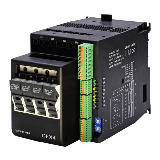
GFX4
4 ZONE MODULAR POWER CONTROLLER
INDEX
2
3
10
GRAPHIC SYMBOLS
INSTALLATION AND
OPERATION MANUAL
Software version: 1.0x
code 80395G - 09/2010 ENGLISH
3.4
Connector J2 power supply, digital inputs
3.5
3.6
Connector J4 Inputs IN1...IN4
3.7
3.8
3.9
3.10
Connection example: power section
4
Installation of serial network
4.1
AUTOBAUD sequence
4.2
Software On/Off
5
6
Technical-Commercial information
6.1
Indicates a suggestion based on the experience
of GEFRAN's Technical Personnel that could be
especially useful under certain circumstances.
Indicates a reference to Detailed Technical
Documents available on the GEFRAN website www.
gefran.com.
30
31
34
1
Advertisement
Table of Contents

Related Manuals for gefran GFX4


Summary of Contents for gefran GFX4
- Page 1 Indicates a suggestion based on the experience Indicates contents of sections, general instructions, notes, and of GEFRAN’s Technical Personnel that could be other points to which the reader’s attention needs to be called. especially useful under certain circumstances.
-
Page 2: Preliminary Instructions
It offers an exclusive combination of performance, reliability, Fuse holders present and flexibility. In particular, this new line of Gefran controllers is the ideal solution for sectors demanding high performance and See paragraph 2.1 “ Dimensions and mounting” before installing continuity of service, such as: the GFX4 controller on the machine/host system control panel. -
Page 3: Installation And Connection 3
(electromagnetic compatibility) conformity that work in DC. in compliance with Directive EMC 2004/108/CE. Series GFX4 controllers are mainly intended for industrial GEFRAN S.p.A. assumes no liability for any use, installed on panels or control panels of production damage to persons or property deriving from process machines or systems. - Page 4 WARNING Conformity UL for SCCR (Short Circuit Current Rating) 100kA for models: GFX4 - XX - X - X - 0 - X Suitable for use on a circuit capable of delivering not more than 100RMS kA symmetrical, 480VAC when protected only by listed cartridge fuses manufactured by BUSSMAN type DFJ200 non renewable (JDDZ) 200A class J current limiting fuses.
- Page 5 INSULATION DIAGRAM 80395G_MHW_GFX4_09-2010_ENG...
-
Page 6: Dimensions
imensions Fastening may be done on DIN guide (EN50022) or with (5MA). See figures 1 and 2. All dimensions are expressed in mm. Figure 1 Model without fuse holder 101,5 1 4 0 109,5 1 4 7 Figure 2 Model with fuse holder 101,5 109,5 80395G_MHW_GFX4_09-2010_ENG... -
Page 7: Installation
nstallation Attention: respect the minimum distances shown in figure 3 to provide adequate air circulation. Figure 3 > 20 mm 0 mm For correct attachment/release of the module on the DIN guide, do as follows: - keep the attach/release cursor pressed - insert/remove the module - release the cursor Figure 4... -
Page 8: Power Connections
eneral Description Figure 7 DIN bar for modules, for example, signal converters (only on models without fuse holders). access for screwdriver to power connector screws power connection terminals ventilation grill: DO NOT OBSTRUCT cursor for insertion/removal of DIN attachment screw seats for fastening module on plate dip switches for function configuration connectors for communication ports (Port1, Port2) rotary switches for setting node address or number... - Page 9 leaning checking or replacing the fan Figure 10 ventilation air intake grill Do as follows: remove the fan grill detach the connector clean or replace the fan nserting the fielD bus interface boarD Figure 11 Do as follows:: Unscrew screw 16 With a screwdriver, gently apply leverage at points 18 Remove cover 17...
- Page 10 3 • ELECTRICAL CONNECTIONS ower connections Figure 12 model without fuse holder Figure 13 model with fuse holder F1,F2,F3,F4 Line connection terminals F1,F2,F3,F4 Line connection terminals U1,U2,U3,U4 Load connection terminals U1,U2,U3,U4 Load connection terminals Table 4 Model 30kW 60kW 80kW max current 32A (30A)* 57A (40A)*...
- Page 11 nput utput onnections Use adequate compensated cable for thermocouple inputs. Respect polarity by avoiding junctions on the cables. If the thermocouple is grounded, the connection must be at a single point. For resistance thermometer inputs, use copper extension cables. Resistance must not exceed 20 ohm; avoid junctions on the cables.
- Page 12 5...10 onnector outputs If auxiliary outputs (O5...O8), are present, connector J1a becomes J1. Figure 15 Connector J1 Table 8 0,2 - 2,5mm 24-14AWG 0,25 - 2,5mm 23-14AWG Outputs 5...8 logic/continuous type Logic outputs 18...36Vdc, max 20mA Continuous outputs: voltage (default) 0/2...10V, max 25mA current 0/4...20mA, max 500Ω...
- Page 13 Where use of the type “C” output continues, voltage or current setting is carried out using jumpers present on the board as in the following figure 16a Figure 16a Connection for logic/continuous utputs voltage current GFX4 OUT-C GFX4 OUT-C 80395G_MHW_GFX4_09-2010_ENG...
- Page 14 Outputs 5...8 triac type Triac outputs Vac = 24...230Vac, max 1A Figure 17 Connection scheme for triac outputs Com 5√8 Table 9 Name Description Outputs common Com 5-8 Output 5 Output 6 Output 7 Output 8 Outputs 5...8 relay type Outputs Out 5...8 relay Ir = 3A max, NO V = 250V/30Vdc cosϕ...
- Page 15 1, 2 onnector power supply Digital inputs Figure 20 Table 12 0,14 - 0,5mm 28-20AWG 0,25 - 0,5mm 23-20AWG Figure 21 Connection scheme for digital inputs and power supply Table 13 Name Description = 18...32Vdc Ground Power supply 18...32Vdc Digital input 1 Digital input 2 80395G_MHW_GFX4_09-2010_ENG...
- Page 16 5...8 onnector auxiliary inputs Figure 22 Table 14 0,14 - 0,5mm 28-20AWG 0,25 - 0,5mm 23-20AWG Figure 23 Connection scheme for 60mV/TC Table 15 auxiliary linear inputs Name Description 60mV Auxiliary input 5 Auxiliary input 6 Auxiliary input 7 Auxiliary input 8 80395G_MHW_GFX4_09-2010_ENG...
- Page 17 1...4 onnector inputs Figure 24 Table16 0,2 - 2,5mm 24-14AWG 0,25 - 2,5mm 23-14AWG Figure 25 Connection scheme for 60mV TC/linear input Table17 60mV/Tc 1V/20mA Pt100 linear input linear input input IN1+ Figure 26 Connection scheme for Pt100 input IN2+ IN3+ IN4+ Figure 27...
-
Page 18: Description Of Dip-Switches
Description of dip-switches Figure 28 Table 18 Description dip-switches Connection type: (see table 18-a) Connection type: (see table 18-a) Connection type: (see table 18-a) = ON 60Hz (OFF 50Hz) = ON reset factory configuration = ON Geflex simulation function = ON insert line termination for Port1 / RS485 Table 18-a Connection type... - Page 19 erial communication ports Port1 (local bus): Modbus serial interface – connectors S1, S2, S3 Figure 29 Tx/Rx- Tx/Rx+ GNDI Tx/Rx- Tx/Rx+ Port 1 GNDI Port 2 Connector S3 to connection at GFX-OP terminal or to Geflex slave modules (GFX-S1, GFX-S2) Table 19 Connector S1/S2 Nr.
- Page 20 Port2 (fieldbus): connectors S4, S5 MODBUS RTU/MODBUS RTU Figure 30 Port2: Fieldbus Modbus RTU/Modbus RTU Interface Connector S5 Connector S4 Line termination (*) Table 20 Connector S4/S5 Nr. Pin Name Description Note RJ10 4-4 pin GND1 (**) (*) Insert the line termination in the last device on the Modbus line.
- Page 21 Port2 (fieldbus): connectors S4, S5 MODBUS RTU/Profibus DP Figure 31 Port2: Fieldbus Modbus RTU/Profibus DP Interface S5 female connector S4 female connector Yellow Led Red Led Green Led Table 21 Connector S4 Nr. Pin Name Description Note RJ10 4-4 pin GND1 (**) (**) Connect the GND signal among Modbus devices with a line...
- Page 22 Port2 (fieldbus): connectors S4, S5 MODBUS RTU/CANopen Figure 32 Port2: Fieldbus Modbus RTU/CANOpen Interface S5 male connector S4 female connector Red Led Green Led Table 23 Connector S4 Nr. Pin Name Description Note RJ10 4-4 pin GND1 (**) (**) Connect the GND signal among Modbus devices with a line Rx/Tx+ Data reception/transmission (A+)
- Page 23 Port2 (fieldbus): connectors S4, S5 MODBUS RTU/DeviceNet Figure 33 Port2: Fieldbus Modbus RTU/DeviceNet Interface S5 male connector S4 female connector Red Led Green Led Table 25 Connector S4 Nr. Pin Name Description Note RJ10 4-4 pin GND1 (**) (**) Connect the GND signal among Modbus devices with a line Rx/Tx+ Data reception/transmission (A+)
- Page 24 Port2 (fieldbus): connectors S4, S5 Modbus RTU / Ethernet Modbus TCP Figure 34 Port2: Modbus RTU / Ethernet Modbus TCP Interface S5 female connector S4 female connector Yellow Led Green Led Table 26 Connector S4 Nr. Pin Name Description Note RJ10 4-4 pin GND1 (**) (**) Connect the GND signal...
- Page 25 Integration of GFX4 with GEFLEX modules connected in RS485 Modbus Figure 35 PORT1/S2 PORT1/S1 PORT1/S1 PORT1/S3 Figure 36 Supervision from PC/PLC simultaneous with GFXOP configuration terminal (each module must have a fieldbus interface) PORT1/S1 PORT1/S1 PORT1 / S3...
- Page 26 Id = load current Figure 39 Connection example for one 3-phase load, stare with neutral only for models: GFX4-x-x2-x / GFX4-x-x-4-x can be equipped for diagnostics and/or load current values. Id = ___ Vd =...
- Page 27 Figure 40 Connection example for one 3-phase load, open triangle Id = ___ line voltage Id = load current total power Figure 41 Connection example for two 3-phase loads, star without neutral Id = V 3 . V line voltage Id = load current total power...
- Page 28 Figure 42 Connection example for two 3-phase loads, closed triangle V 3 . V line voltage Id = load current total power 80395G_MHW_GFX4_09-2010_ENG...
- Page 29 They are positively identified by means of a node address (ID) set on rotary switches (tens + units). A maximum of 99 GFX4 modules can be installed in a serial network, with node address selectable from “01” to “99” in standard mode or can also create a network with GFX4 and Geflex mixed in Geflex compatible mode, in which each GFX4 identifies 4 zones with sequential node address starting with the code set on the rotary switches.
- Page 30 1) Connect the serial cables for all modules on the network to serial 1 and to the supervision terminal. INSTALLATION OF 2) Set the rotary switch on the GFX4 modules to be installed, SERIAL NETWORK 1 or on all modules present in case of first installation, to ModBus position “0+0”.
- Page 31 5 • TECHNICAL DATA INPUTSI IN1,…,IN4 analog process inputs Function Acquisition of process variable Max. Error 0,2% f.s. ± 1 scale point at room temperature of 25°C Thermal drift < 100 ppm/°C f.s. Sampling time 120 ms Thermocouple Tc (ITS90) J,K,R,S,T (IEC 584-1,CEI EN 60584-1, 60584-2) Fault cold junction comp 0,1°/°C...
- Page 32 COMMUNICATION PORTS PORT1 (present) Function Local serial communication Protocol ModBus RTU Baudrate Settable to 1200,…,115200, (default 19,2Kbit/s) Address node Settable by rotary switch Type RS485 1500V isolation, double connector RJ10 telephone type 4-4 PORT2 (Fieldbus option) Function Fieldbus serial communication Protocol ModBus RTU, type RS485, baudrate 1200...115000Kbit/s CANOpen 10K…1Mbit/s...
- Page 33 1200g. models 30Kw, 60Kw con fusibili 1600g. 5.1 Voltage/Current Table Current (Amp) Voltage (Vac) Power (kW) Model range nominal working total single max for GFX4 for channel contemporary channel single channel (4x16x110) (16x110) (1x16x110) (4x16x230) (16x230) (1x16x230) 14,7 24...530 (4x16A)
-
Page 34: Accessories
4 Current Transformers + 4 Linear inputs (**) (**) Option NOT available with Fieldbus E1 or E2 GEFRAN spa reserves the right to make any aesthetic or functional changes at any time and without notice. ccessories KIT WINSTRUM Software for management / configuration of Geflex units A simple and intuitive interface lets you change the most important parameters of all Geflex models. - Page 35 Gefran GFX4 Controller: Installation Tel: +27 11 966 9800 (JHB) +27 21 762 8995 (CT) sales@thermon.co.za www.unitemp.com/contact...
Need help?
Do you have a question about the GFX4 and is the answer not in the manual?
Questions and answers