Sign In
Upload
Manuals
Brands
gefran Manuals
Controller
GPC
gefran GPC Manuals
Manuals and User Guides for gefran GPC. We have
1
gefran GPC manual available for free PDF download: Configuration And Programming Manual
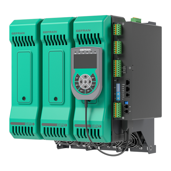
gefran GPC Configuration And Programming Manual (156 pages)
Advanced Power Controller
Brand:
gefran
| Category:
Controller
| Size: 7 MB
Table of Contents
Table of Contents
3
Disposal
7
Preface
7
Typographical Conventions Used in the Manual
7
Warnings and Safety
7
Copyright
9
Liability Disclaimer
9
1 General Description
11
Summary
11
Field of Application
11
Technicians and Operators
11
2 Commissioning
13
Commissioning Operations
13
Programming Tool
13
Gf_Express
13
System Requirements
13
First Power-On
14
3 Configuration
15
Parameter Legend
15
Legend for Functional Parameter Diagrams
16
Modes of Use
16
Functional Diagram of Single-Node Mode
16
Functional Diagram of Multi-Node Mode
17
Serial Communication (Modbus)
17
Addressing (Cod)
17
Single-Node Mode
17
Custom Modbus Memory Map
17
Multi-Node Mode
18
Time Constraints of Serial Communication
18
Connections
19
Modbus Network Installation
19
Communication Error
19
Device Identification Code
19
Serial Port Transmission Speed
19
Communication Error Timeout
20
Power Delivery Mode with Communication Error
20
Output Power with Communication Error
20
Analog Inputs
21
Functional Diagram of Analog Inputs
21
Types of Analog Input
21
Analog Input Lower Scale Limit
21
Analog Input Upper Scale Limit
22
Analog Input Offset
22
Analog Input Low-Pass Filter
22
Analog Input Process Value
23
Measuring Load Current
23
Ammeter Input Lower Scale Limit
25
Ammeter Input Upper Scale Limit
25
Ammeter Input Offset
25
Transformation Ratio for External CT Input
26
Instantaneous Ammeter Input Value
26
Filtered Ammeter Input Value
26
Peak Ammeter Input Value
26
Power Factor
27
RMS Load Current
27
RMS Current in Three-Phase Load
27
Ammeter Input Digital Filter
27
Measuring Load Voltage
28
RMS Load Voltage
29
Instantaneous Load Voltage
29
Load Voltage with Output Activated
30
Voltage on Three-Phase Load
30
Lower Voltmeter Input Scale Limit
30
Upper Voltmeter Input Scale Limit
30
Voltmeter Input Offset
31
Voltmeter Input Digital Filter
31
3.10. Measuring Line Voltage
31
Lower VT Voltmeter Input Scale Limit
33
Upper VT Voltmeter Input Scale Limit
33
VT Voltage Transformer Input Offset
33
Three-Phase Line Unbalance Threshold
34
Voltmeter Input Value
34
Filtered Voltmeter Input Value
34
Voltage_Status
34
Grid Frequency
35
VT Voltmeter Input Digital Filter
35
3.11. Measuring the Power on the Load and Energy Consumed
36
Power on Load
37
Power on Three-Phase Load
37
Load Impedance
37
Three-Phase Load Impedance
37
E1 Energy Consumed
37
E2 Energy Consumed
38
E1 Three-Phase Energy Consumed
38
E2 Three-Phase Energy Consumed
38
E1 Energy Consumption Meter Reset
38
E2 Energy Consumption Meter Reset
39
3.12. Digital Inputs
39
Definition of Digital Input Types
41
Digital Input Status
41
Digital Input Function
42
PWM Input Timeout
43
Digital Filter for PWM Input
43
PWM Input Value
43
Generic Alarms AL1
44
Enable Alarms
45
Generic Alarm Reference Variable Selection
46
Alarm Threshold
48
Alarm Hysteresis
50
Alarm Type
51
Direct Setting of a Direct or Reverse Alarm
53
Direct Setting of an Absolute or Relative Alarm
54
Direct Setting of a Normal or Symmetrical Alarm
55
Direct Setting of Alarm Enabling at Startup
56
Direct Setting of Alarm Memory Activation
57
Alarm Validation Power
58
Alarm Status Reading
59
Alarm Memory Reset
60
Alarm Status (ALSTATE_IRQ)
60
3.14. HB (Heater Break) Alarms
61
Enabling Alarms
65
HB Alarm Function
65
Delay Time for HB Alarm Activation
66
Enabling Calibration
66
HB Alarm Threshold
66
HB Alarm Threshold Percentage
67
CT Reading in HB Calibration
67
VT Reading in HB Calibration
67
Ou.p Power in Calibration
67
HB Calibration with IR Lamp (Current)
68
HB Calibration with IR Lamp (Voltage)
70
HB Alarm Threshold as Function of Power on Load
71
HB (or TA1-TA2-TA3) or POWER FAULT Alarm Status
71
HB Alarm Status (Single-Phase Configuration or CT Phase 1 Two-Phase or Three-Phase Configuration)
72
HB Alarm Status (Single-Phase Configuration or CT Phase 2 Two-Phase or Three-Phase Configuration)
72
HB Alarm Status (Single-Phase Configuration or CT Phase 3 Three-Phase Configuration)
72
ALSTATE Alarm Status for Single-Phase Loads and Phase 1 of Three-Phase Loads
73
ALSTATE_HB Alarm Status (Phase 2 of Two-Phase/Three-Phase Loads and Phase 3 of Three-Phase Loads)
73
Alarm Status (ALSTATE_IRQ)
73
Alarm Reset
73
Current)
74
Enable POWER_FAULT Alarms
74
HB, SSR_SHORT, NO_VOLTAGE and NO_CURRENT
75
SSR_SHORT Update Frequency
75
Alarms
75
Alarm Reset
75
Status 3 (STATUS3)
75
SSR_SHORT Alarm Status (Single-Phase Configuration or CT Phase 1 Two-Phase or Three-Phase Configuration)
76
SSR_SHORT Alarm Status (Single-Phase Configuration or CT Phase 2 Two-Phase or Three-Phase Configuration)
76
SSR_SHORT Alarm Status (Single-Phase Configuration or CT Phase 3 Three-Phase Configuration)
76
VOLTAGE Alarm Status (Single-Phase Configuration or CT Phase 1 Two-Phase or Three-Phase Configuration)
77
VOLTAGE Alarm Status (Single-Phase Configuration or CT Phase 2 Two-Phase or Three-Phase Configuration)
77
VOLTAGE Alarm Status (Single-Phase Configuration or CT Phase 3 Three-Phase Configuration)
77
CURRENT Alarm Status (Single-Phase Configuration or CT Phase 1 Two-Phase or Three-Phase Configuration)
78
CURRENT Alarm Status (Single-Phase Configuration or CT Phase 2 Two-Phase or Three-Phase Configuration)
78
CURRENT Alarm Status (Single-Phase Configuration or CT Phase 3 Three-Phase Configuration)
78
3.16. Thermal Protection Alarms
79
SSR Heat Sink Temperature Value
80
Temperature Value of LINE Terminals
80
Temperature Value of LOAD Terminals
80
Temperature Value of the Power Board
80
Maximum Temperature Value of SSR Heat Sink
81
Maximum Temperature Value of the Power Board
81
Status Reading (STATUS4)
82
Max1 Temperature Reset
82
3.17. FUSE_OPEN and SHORT_CIRCUIT_CURRENT Alarms
83
Number of Automatic Restarts
83
FUSE_OPEN and SHORT_CIRCUIT_CURRENT Alarm Reset
83
STATUS4 State Reading
83
3.18. General Description of the Outputs
84
3.19. Allocation of Reference Signals to Outputs
86
Allocation of Reference Signal
86
OUT Cycle Time
88
Status Rl.X (MASKOUT_RL)
88
Status Rl
89
Allocation of Physical Outputs
90
Alarm Status Masks for Custom Output 9
91
Alarm Status Masks for Custom Output 10
91
Status Reset to Last Activation of Custom OUT9
92
Status Reset to Last Activation of Custom OUT10
92
Physical Output Status
92
Rl.X (MASKOUT_OUT) Status
93
Alarm Status Stored at Last Activation for Custom Output
93
STATUS4 Stored with Custom Output Activation
94
ALSTATE_IRQ Stored with Custom Output Activation
94
VOLTAGE_STATUS Stored with Custom Output Activation
94
3.20. Analog Outputs
95
Types of Analog Output
96
Analog Output Reference Allocation
97
Lower Analog Output Scale Limit
98
Upper Analog Output Scale Limit
98
Serial Line Value for Analog Output
98
Analog Output Value
99
3.21. Controls - General Description
99
Reference Power
101
Output Power Value
101
Output Power Value Without Correction
101
Power Output Percentage
102
Output Power Offset
102
Control Output Gradient
102
Minimum Trigger Output
102
Automatic - Manual Control
103
Manual Power
103
Automatic - Manual Selection
103
Status (STATUS_W)
104
Manual Power Correction
104
Mains Voltage
104
Enabling Manual Power Correction and Storage
105
3.24. Start Modes
105
Start Mode at Power-On
105
Software Shutdown
106
Software Startup/Shutdown
106
Software Shutdown Modes
106
3.26. Other Functions
107
Operating Hour Meter
107
Enabling Retentive Memory Storage
107
3.27. Power Control Modes
108
Enabling Trigger Modes
109
Maximum RMS Current Limit in Steady State
110
Minimum Number of Cycles of BF Mode
110
3.28. Softstart
111
Maximum Phase of the Phase Softstart Ramp
111
Phase Softstart Ramp Duration
111
Minimum Non-Conduction Time for Ramp Reactivation
112
Maximum Peak Current Limit During Ramp
112
Phase Softstart Ramp Restart
113
Phase Softstart Ramp Status
113
Phase Softstart Ramp Completion Status
113
3.29. Delay Triggering
114
Delay Triggering with Rotation of Phases 1-3-2
114
3.30. Automatic Firing Change Function
115
Enabling Firing Change Function
115
Current Threshold for Activating Firing Change
116
Current Hysteresis for Activating Firing Change
116
Minimum Power for Activating Firing Change
116
Firing Change Status Set Via Serial
117
3.31. Feedback Mode
118
Enabling Feedback Mode
119
Maximum Voltage Feedback Correction
119
Maximum Current Feedback Correction
119
Maximum Power Feedback Correction
120
Voltage Feedback Reference
120
Current Feedback Reference
120
Power Feedback Reference
120
Feedback Response Speed
121
Feedback Reference Calibration
121
Feedback Reference
121
3.32. Heuristic Power Control
122
Enabling Heuristic Power Control
122
Maximum Current for Heuristic Power Control
122
3.33. Heterogeneous Power Control
123
Enabling Heterogeneous Power Control
123
Maximum Current for Heterogeneous Power Control
123
3.34. Virtual Instrument Control
124
Enabling Instrument Control Via Serial
124
Input Control from Serial
124
Output Control from Serial
125
LED and Digital Input Control from Serial
125
Virtual Register Address Table
126
HW and SW Information
127
Software Version Code
127
Hardware Configuration Codes
127
Hardware Configuration Codes 1
128
Hardware Configuration Codes 2/3/4
128
Fieldbus Board Firmware Version
129
Fieldbus Board Node
129
Fieldbus Board Baudrate
129
I/O Data Size for Fieldbus
129
Jumper / DIP Switch Status
130
Enabling Virtual DIP Switch Control
130
Virtual DIP Switch Status
131
Manufacturer Identification
131
Product Identification
131
LED Operation
131
RN - er - DI1 - DI2 LED Function
132
O1 - O2 - O3 LED Function
133
Status (STATUS_W)
133
Alarm Status Reading
133
Status (STATUS)
134
Status 1 (STATUS1)
134
Status 2 (STATUS2)
135
Status 3 (STATUS3)
135
Status 4 (STATUS4)
135
Voltage Status (VOLTAGE_STATUS)
135
3.36. Key Functions
136
4 Examples and Application Notes
137
Setting Parameters LS.A1/LS.A2/LS.A3 and HS.A1/HS.A2
137
Hs.a3
137
Full Input Voltage Range
137
Input Voltage Range Limited Downwards
137
Input Voltage Range Limited Upwards
137
Formulas for Calculating Ls.ax and Hs.ax
137
Using a Function Associated with the Digital Input and Via Serial
138
Using Digital Input 1 to Enable Software Startup
139
Alarms
140
Generic Alarms AL1
140
HB Alarm
141
HB Alarm Threshold Teach-In Function
141
Heuristic Power Control
142
5 Using the GFW/GPC-OP Keypad
143
Description
143
Legend
143
Operations
144
HOME Screen
144
Accessing the Menu
144
Browsing the Menus
144
Parameter Display
144
Changing a Numerical Parameter
145
Changing a Status Parameter
145
ALARM Screen
145
Alarm Reset
145
Menu Structure
146
Main Menu and 2Nd Level Menu
146
00 CURRENT LIMIT - 3Rd Level Menu
147
01 STATUS - 3Rd Level Menu
147
03 COMMS - 3Rd Level Menu
148
04 INPUTS - 3Rd Level Menu
148
05 ALARMS - 3Rd Level Menu
149
06 OUTPUTS - 3Rd Level Menu
150
07 CONTROLS - 3Rd Level Menu
151
08 SPECIAL FUNCTIONS - 3Rd Level Menu
151
VIRTUAL - 3Rd Level Menu
152
POWER CONTROLS - 3Rd Level Menu
152
CUSTOM MAP - 3Rd Level Menu
153
COMMANDS - 3Rd Level Menu
153
6 Accessories
154
Advertisement
Advertisement
Related Products
gefran GPC 40-600A
gefran GFX4
gefran GFW 400-600A
gefran GFW ADV
gefran GEFLEX GFX-E1 Series
gefran GFX4-IR 30
gefran GTF
gefran GTF 90
gefran GFW 500A
gefran GRM-H 30
gefran Categories
Controller
Control Unit
Relays
Inverter
DC Drives
More gefran Manuals
Login
Sign In
OR
Sign in with Facebook
Sign in with Google
Upload manual
Upload from disk
Upload from URL