gefran GFX4 Configuration And Programming Manual

gefran GFX4 Configuration And Programming Manual

4-zone modular power controller
Hide thumbs Also See for GFX4:

Advertisement

LIST OF ATTACHMENTS
This document supplements the following manuals:
- Instructions and warnings for GFXTERMO4
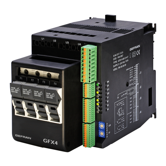
- Instructions and warnings for GFX4
80397M_MSW_GFX4-GFXTERMO4_08-2018_ENG
GFX4 / GFXTERMO4
4-ZONE MODULAR POWER CONTROLLER
CONFIGURATION AND
PROGRAMMING MANUAL
Software version: 2.1x
code: 80397M - 08-2018 - ENGLISH
ATTENTION!
This manual is an integral part of the product,
and must always be available to operators.
This manual must always accompany the
product, including if it is transferred to another user.
Installation and/or maintenance workers MUST
read this manual and scrupulously follow all of the
instructions in it and in its attachments. GEFRAN will
not be liable for damage to persons and/or property, or
to the product itself, if the following terms and condi-
tions are disregarded.
The Customer is obligated to respect trade se-
crets. Therefore, this manual and its attachments may
not be tampered with, changed, reproduced, or trans-
ferred to third parties without GEFRAN's authorization.
1

Advertisement

Table of Contents
loading

Summary of Contents for gefran GFX4

  • Page 1 Installation and/or maintenance workers MUST read this manual and scrupulously follow all of the instructions in it and in its attachments. GEFRAN will not be liable for damage to persons and/or property, or to the product itself, if the following terms and condi- tions are disregarded.
  • Page 2 880397M_MSW_GFX4-GFXTERMO4_08-2018_ENG...
  • Page 3: Table Of Contents

    TABLE OF CONTENTS AND SUMMARIES INTRODUCTION ..............4 HOT RUNNERS CONTROL ..........53 FIELD OF USE ..............4 FAULT ACTION POWER ..........53 CHARACTERISTICS OF PERSONNEL ......4 POWER ALARM ............53 STRUCTURE OF THIS MANUAL ........5 SOFTSTART FOR PREHEATING ........55 HEATING OUTPUT (Fast cycle) ........56 INSTRUMENT ARCHITECTURE ........6 POWER CONTROL ............56 SERIAL COMMUNICATION (MODBUS) ......7...
  • Page 4: Introduction

    Since it is impossible to foresee all of the installations and environments in which the instrument may be applied, adequate technical preparation and complete knowledge of the instrument’s potentials are necessary. GEFRAN declines all liability if rules for correct installation, configuration, and/or programming are disregarded, as well as all liability for systems upline and/or downline of the instrument.
  • Page 5: Structure Of This Manual

    This manual was originally written in ITALIAN. Therefore, in case of inconsistencies or doubts, request the original manual or explanations from GEFRAN. The instructions in this manual do not replace the safety instructions and the technical data for installation, configuration and programming applied directly to the product or the rules of common sense and safety regulations in effect in the country of installation.
  • Page 6: Instrument Architecture

    - GFX compatible mode: as if there were 4 separate instruments (recommended for retrofitting projects and/or replacement of damaged instruments); - GFX4 mode: as a single instrument with the same functions as 4 separate instruments, but with possibility of inter- action among the various parameters, inputs and outputs (recommended for new projects).
  • Page 7: Serial Communication (Modbus)

    14, node 14 addresses Zone 1, node 15 Zone 2, node 16 Zone 3, node 17 Zone 4. The process variable (PV) for Zone 1 has address Cod 0, the PV for Zone 2 has address Cod+1, 0, etc... Parameter out.5, which defines the function of output OUT 5 on the GFX4, has address Cod 611. 80397M_MSW_GFX4-GFXTERMO4_08-2018_ENG...
  • Page 8: Connection

    There is a single value (Cod) set on the rotary switches; i.e., one for each GFX4 instrument. To access the data in each zone, simply add an offset to the address (+1024 for Zone 1, +2048 for Zone 2, +4096 for Zone 3, +8192 for Zone 4).
  • Page 9 - parity Serial 2 = none You can install a maximum of 99 GFX4 modules in a serial network, with node address selectable from “01” to “99” in stand- ard mode, or create a mixed GFX4 / Geflex network in Geflex compatible mode in which each GFX4 identifies 4 zones with sequential node address starting from the code set on the rotary switches.
  • Page 10: Inputs

    INPUTS MAIN INPUT The modular power controller has 4 main inputs to control 4 temperature zones, to which you can connect temperature sensors (thermocouples and RTD), linear sensors or custom sensors to acquire process variable (PV) values. To configure, you always have to define the type of probe or sensor (tYP), the maximum and minimum scale limit (Hi.S –...
  • Page 11 Lock\Unlock objects access 1: Free access to all modbus object LOCK_UNLOCK_DATA_AREA_ACCESS 65529 parameters. 0: Access limited ONLY to Custom Map Data Area Note : Background task must be used ONLY when compatible mode is setting on GFW, GFX4\GFXTERMO4, GFX4-IR. 80397M_MSW_GFX4-GFXTERMO4_08-2018_ENG...
  • Page 12 Probes and sensors tYP. Table of probes and sensors Probe type, signal, enable, custom linearization and main input scale TC SENSOR Type of probe Scale Without dec. point With dec. point TC J °C 0/1000 0.0/999.9 TC J °F 32/1832 32.0/999.9 TC K °C...
  • Page 13 Read state Read of engineering value of P.V. process variable (PV) Self-diagnostic error code Error code table of main input No Error For custom linearization (tYP = 28 or 29): Lo (process variable value is < Lo.S) - LO is signaled with input values below Lo.S or at minimum Hi (process variable value is >...
  • Page 14 The engineering values calculated in this way by the user can be set by means of the following parameters. Engineering value attributed to Point 0 S. 0 0 (- 1999 ... 9999) (minimum value of input scale) Engineering value attributed to S.
  • Page 15: Ct Auxiliary Input (Ammeter)

    1, line 2 and line 3, respectively. Models with 1 CT (GFX4-x-x-1-x-x and GFX4-x-x-3-x-x) sample the load current value at a programmable time in- terval (parameter dG.t). Therefore, you can use the best sampling time for the application being run and, especially, for load type, since activation of the scan to identify faults on the load with fast systems and short cycle times may be critical for stable temperature control.
  • Page 16 Input sampling interval dG. t CT input sampling interval 10 ...999 sec Only for GFX4 1TA Sets an interval for the sampling load current value for activation of the SSR_SHORT and NO_CURRENT alarms (see: Power Fault ALARMS). SCHEMA FUNZIONALE Internal variable I.tA1...
  • Page 17: Voltage Value On The Load (Voltmeter)

    VOLTAGE VALUE ON THE LOAD (Voltmeter) The voltage read value is present for each zone only on models with 4 CTs (GFX4-x-x-2-x-x and GFX4-x-x-4-x-x), and is used to monitor voltage applied to a single-phase or 3-phase load, with automatic recognition of the internal voltmeter transformer.
  • Page 18 Scale limits Maximum scale limit of voltage 530,0 x. t U1 0.0 ... 999.9 transformer TV input (phase 1) Maximum scale limit of voltage 530,0 x. t U2 0.0 ... 999.9 With 3-phase load transformer TV input (phase 2) Maximum scale limit of voltage 530,0 x.
  • Page 19: Auxiliary Analog Input (Lin/Tc)

    AUXILIARY ANALOG INPUT (LIN/TC) The GFX4 has 4 inputs defined as auxiliary (IN5 for zone 1, IN6 for zone 2, IN7 for zone 3, IN8 for zone 4) to which TC or linear temperature sensors can be connected. The presence of these inputs is optional and, for models GFX4-x-x-3-x-x/GFX4-x-x-4-x-x, is defined by the order code.
  • Page 20 Read state In. 2 Value of auxiliary input Error code for self-diagnosis Er. 2 Error code table of auxiliary input No error Lo (value of process variable is < Lo.S) Hi (value of process variable is > Hi.S) ERR [third wire interrupted for PT100 or input values below minimum limits (ex.: for TC with connection error)] SBR (probe interrupted or input values beyond maximum limits) ADVANCED SETTINGS...
  • Page 21: Digital Inputs

    DIGITAL INPUTS There are always two inputs. Each input can perform various functions based on the setting of the following parameters: diG. Digital input function Digital input functions table Activation No functions (input off) On leading edge MAN/AUTO controller diG. 2 Digital input 2 function On leading edge LOC / REM...
  • Page 22: Using A Function Associated With Digital

    USING A FUNCTION ASSOCIATED WITH DIGITAL INPUT AND VIA SERIAL At power-on or on the leading edge of digital input 1 or 2, all zones assume the state set by the digital input. For each zone, this state can be changed by writing via serial. The setting via serial is saved in eeprom (STATUS_W_EEP, address 698).
  • Page 23: Using A Function Of Digital Input 1 To Enable

    USING A FUNCTION OF DIGITAL INPUT 1 TO ENABLE AT SOFTWARE ON Software ON can be configured either by enabling a digital input or by writing via serial. Enabling by digital input 1 1 (diG) is common to all zones, whereas enabling via serial is specific for each individual zone. The ON/OFF setting via serial is saved in eeprom (STATUS_W_EEP, address 698 bit 3) for resetting of the condition at the next hardware power-on;...
  • Page 24: Alarms

    ALARMS GENERIC ALARMS AL1, AL2, AL3 and AL4 Four generic alarms are always available and can perform various functions. Typically, alarm AL.1 is defined as minimum and AL.2 as maximum. These alarms are set as follows: - select the reference variable to be used to monitor the value (parameters A1.r, A2.r, A3.r and A4.r): the origin of the variable can be chosen from the process variable PV (generally linked to the main input), the ammeter input, the voltmeter input, the auxiliary analog input, or the active setpoint.
  • Page 25 Reference variables a1. r Select reference variable alarm 1 Table of alarm reference setpoints Variable to be compared Reference setpoint A2. r Select reference variable alarm 2 PV (process variable) in.tA1 (In.tA1 OR In.tA2 OR In.tA3 WITH 3-PHASE LOAD) A3. r Select reference variable alarm 3 In.tV1 (In.tV1 OR In.tV2 OR In.tV3...
  • Page 26 Alarm type a1. t Alarm type 1 Table of alarm behaviour Direct (high limit) Absolute Normal A2. t Alarm type 2 Inverse (low limit) Relative Symmetrical to activfe setpoint (window) direct absolute normal inverse absolute normal A3. t Alarm type 3 direct relative normal...
  • Page 27 Enable alarms AL. n Select number of enabled alarms Table of enabled alarms AL.nr Alarm 1 Alarm 2 Alarm 3 Alarm 4 disabled disabled disabled disabled enables disabled disabled disabled disabled enables disabled disabled enables enables disabled disabled disabled disabled enables disabled enables...
  • Page 28 FUNCTIONAL DIAGRAM Alarm setpoint Type of alarm and State of alarm AL1 hysteresis (A1.t, HY.1) Type of alarm and Alarm setpoint State of alarm AL2 hysteresis (A2.t, HY.2) See outputs Type of alarm and Alarm setpoint State of alarm AL3 hysteresis (A3.t, HY.3) Alarm setpoint...
  • Page 29: Lba Alarm (Loop Break Alarm)

    LBA ALARM (Loop Break Alarm) This alarm identifies incorrect functioning of the control loop due to a possible load break or to a short circuited or reversed probe. With the alarm enabled (parameter AL.n), the instrument checks that in condition of maximum power delivered for a settable time (Lb.t) greater than zero, the value of the process variable increases in heating or decreases in cooling: if this does not happen, the LBA alarm trips.
  • Page 30: Hb Alarm (Heater Break Alarm)

    HB ALARM (Heater Break Alarm) This type of alarm identifies load break or interruption by reading the current delivered by means of a current trans- former. The following three fault situations may occur: - delivered current is lower than theoretical current: this is the most common situation, and indicates that a load ele- ment is breaking.
  • Page 31 Alarm setpoints HB alarm setpoint (scale points am- 10,0 A. x b1 meter input - Phase 1) HB alarm setpoint (scale points am- 10,0 A. x b2 With 3-phase load meter input - Phase 2) HB alarm setpoint (scale points am- 10,0 A.
  • Page 32: Alarm Sbr - Err

    ALARM SBR - ERR (probe in short or connection error) This alarm is always ON and cannot be deactivated. It controls correct functioning of the probe connected to the main input. In case of broken probe: - the state of alarms AL1, AL2, AL3 and AL4 is set based on the value of parameter rEL; - control power control is set to the value of parameter FAP.
  • Page 33: Power Fault Alarms

    Power Fault ALARMS (SSR_SHORT, NO_VOLTAGE, SSR_OPEN and NO_CURRENT) GFX4 with 4 TA hd. 2 Enable POWER_FAULT alarms Table of Power Fault alarms SSR_SHORT NO_ VOLTAGE SSR OPEN NO_CURRENT NOTE: the NO_CURRENT alarm setpoint is fixed at 1A + 32 alarms with memory Refresh rate SSR_SHORT dg.
  • Page 34 GFXTERMO4 with 4 TA hd. 2 Enable POWER_FAULT alarms Table of Power Fault alarms SSR_SHORT NO_CURRENT NOTE: the NO_CURRENT alarm setpoint is fixed at 1A + 32 alarms with memory Refresh rate SSR_SHORT dg. t 1...999 sec The alarm activates after 3 faults. Time filter for NO_CURRENT alarms dg.
  • Page 35: Overheat Alarm

    Overheat alarm The controller has a temperature sensor for the internal heatsink. The temperature value of the heatsink is in variable INPTC; the over_heat alarm trips when the temperature exceeds 85°C. This condition may be caused by obstructed air vents or by a blocked cooling fan. Is provided the intervention of the alarm also for speed of temperature rise (derivate) INPTC greater than 7°C in 12 seconds.
  • Page 36: Outputs

    OUTPUTS The modular power controller has high flexibility in the assignment of functions to the physical outputs. As a result, the instrument can be used in sophisticated applications. A function is assigned to each physical output in two steps: first assign the function to one of internal reference signals rL.1 ..
  • Page 37 2 AL1 - alarm 1 rL. 3 Allocation of reference signal 3 AL2 - alarm 2 4 AL3 - alarm 3 5 AL.HB or POWER_FAULT with HB alarm (TA1 OR TA2 OR TA3) 6 LBA - LBA alarm rL. 4 Allocation of reference signal 7 IN1 - repetition of logic input DIG1 8 AL4 - alarm 4...
  • Page 38 Read state State of output OUT1 State of output OUT2 State of output OUT3 State of output OUT4 State of output OUT5 State of output OUT6 State of output OUT7 State of output OUT8 State of output OUT9 State of output OUT10 State of outputs OUT 1 OUT 2...
  • Page 39 FUNCTIONAL DIAGRAM Ou.P (Heat) rL.1 - Zone1 Ou.P (Cool) State of AL1 rL.2 - Zone1 State of AL2 State of AL3 State of AL4 Allocation of reference rL.3 or rL.5 - Zone1 signal State of Hb.1 (rL.1, rL.2, State of Hb.2 * rL.3, rL.4, rL.5, rL.6) State of Hb.3 *...
  • Page 40: Settings

    SETTINGS The controller has the following setpoint controls. SETTING THE SETPOINT The active (control) setpoint (SPA) can be set by means of the local setpoint (_SP) or the remote setpoint (SP.rS). A remote setpoint can assume the value of an auxiliary input or one set via serial line (SP.r). The remote setpoint can be defined in absolute value or relative to the local setpoint;...
  • Page 41: Setpoint Control

    SETPOINT CONTROL Set gradient The “Set gradient” function sets a gradual variation of the setpoint, with programmed speed, between two defined values. If this function is active ( g. s p other than 0), at switch- Absolute alarm Setpoint profile on and at auto/man switching the initial setpoint is assumed Referred to current setpoint...
  • Page 42 diG. Digital input function See: Table of digital input functions diG. 2 Digital input function 2 See: Table of digital input functions SELECT OFF = Select SP1 SP1 / SP2 ON = Select SP2 Instrument state Table of instrument settings Select SP1/SP2 Start/Stop Selftuning Select ON/OFF...
  • Page 43: Controls

    If the Integral Time value is too long (weak Integral Action), there may be persistent deviation between the controlled variable and the setpoint. For more information on control actions, contact GEFRAN. 80397M_MSW_GFX4-GFXTERMO4_08-2018_ENG...
  • Page 44 Heat/cool control with separate or superimposed band Output with separate band Output with superimposed band Control output with only proportional action in case of proportional Control output with only proportional action in case of proportional heating band separate from cooling band. heating band superimposed on cooling band.
  • Page 45 Proportional band for heating or hyster- h. p b 0 ...999,9% f.s. esis ON/OFF 148 - 149 4,00 h. 1 t Integral heating time 0.00 ...99,99 min 1,00 h. d t Derivative heating time 0.00 ...99,99 min Proportional band for cooling or hyster- c.
  • Page 46 FUNCTIONAL DIAGRAM (h.Pb, Active setpoint h.it, h.dt, (SPA) PID_POWER c.SP, c.Pb, Output h.b,rSt,A.rS) Power of power reference In.1 - zone1 limits (SPU) Enable PV In.1 - zone2 for zone (SPU) In.1 - zone3 In.1 - zone4 PID_POWER zone 1 PID_POWER zone 2 Power limit for Fault Action (FA.P) PID_POWER zone 3...
  • Page 47: Automatic / Manual Control

    AUTOMATIC / MANUAL CONTROL By means of the digital input function you can set the controller in MAN (manual) and set the control output to a constant value changeable by means of communication. When returning to AUTO (automatic), if the variable is within the proportional band, switching is bumpless. Value of control outputs 0v.
  • Page 48: Manual Tuning

    MANUAL TUNING A) Enter the setpoint at its working value. B) Set the proportional band at 0.1% (with on-off type setting). C) Switch to automatic and observe the behavior of the vari- able. It will be similar to that in the figure: Process D) The PID parameters are calculated as follows: Proportional variable...
  • Page 49 Enable selftuning, s. t v Selftuning, autotuning, softstart table autotuning, softstart Autotuning Selftuning Softstart continuous WAIT WAIT WAIT (*) +16 with automatic switching in GO if PV-SP > 0.5% f.s. +32 with automatic switching in GO if PV-SP > 1% f.s. +64 with automatic switching in GO if PV-SP >...
  • Page 50: Selftuning

    SELFTUNING This function is valid for single-action (either heat or cool) systems and for double-action (heat/cool) systems. Selftuning is activated to calculate the best control parameters when starting the process. The variable (example: temperature) must be the one assumed at zero power (room temperature). The controller supplies the maximum power set until reaching an intermediate point between starting value and the setpoint, then resets power.
  • Page 51: Softstart

    Read state OFF = Selftuning in Stop SELFTUNING STATE ON = Selftuning in Start STATE OF DIGITAL OFF = Digital input 1 off See: Table of digital input functions INPUT 1 ON = Digital input 1 on STATE OF DIGITAL OFF = Digital input 2 off INPUT 2 ON = Digital input 2 on...
  • Page 52: Software Shutdown

    SOFTWARE SHUTDOWN Running the software shutdown procedure causes the following: 1) Reset of Autotuning, Selftuning and Softstart. 2) Digital input (if present) enabled only if assigned to SW shutdown function. 3) In case of switch-on after SW shutdown, any ramp for the set (set gradient) starts from the PV. 4) Outputs OFF: except for rL.4 and rL.6 which are forced ON.
  • Page 53: Hot Runners Control

    HOT RUNNERS CONTROL With the following parameters, you can perform a specific control for the hot runners (hot.runners). The main functions are: FAULT ACTION POWER You can decide what power to supply in case of broken probe. FAP is the reference power for parameter FAP. Average power is the average power calculated in the last 300 sec.
  • Page 54 The alarm is not activated if the control (Ctr) is ON/OFF type, during Selftuning and in Manual. 5 min. PF.t Process variable SP + b.St SP - b.St Power Average power + b.PF Average power Average power - b.PF Alarm power The parameters for alarm power are: 0,0 ...
  • Page 55: Softstart For Preheating

    SOFTSTART FOR PREHEATING This function lets you deliver a settable power (So.P) for time (SoF), after which normal control is resumed by means of PID control. Activation is only at switch-on, with manual-automatic switching during Softstart (the time restarts from 0), and if the process variable is below setpoint SP.S.
  • Page 56: Heating Output (Fast Cycle)

    2 Allocation of reference signal POWER CONTROL SSR CONTROL MODES The following models are available: GFX4 30 kW with full scale 16A in all four zones GFX4 60 kW with full scale 32A in all four zones GFX4 80 kW...
  • Page 57 This function acts by enabling the control to search for the most appropriate input combinations. Example 1: 4 loads 380V- 32A (zone 1), 16A (zone 2), 25A (zone 3), 40A The combination corresponding to current values below the (zone 4) limit value are: (maximum current is 113A in case of simultaneity of conduc- I1+I2 = 48A...
  • Page 58 ZONE 2 ZONE 3 ZONE 4 NOTE: Only for GFX4 with CTs present and outputs OUT1...OUT4 with slow cycle time (1...200sec) all HEAT or all COOL. In case of GFXTERMO4, the 4 CTs must be connected to outputs OUT1...OUT4. Maximum current for heuristic power I.
  • Page 59: Virtual Instrument Control

    VIRTUAL INSTRUMENT CONTROL Virtual instrument control is activated by means of parameter hd.1. By setting parameters S.In and S.Ou you can enable the writing of some parameters via serial line, set the value of inputs and the state of outputs. You have to enable alarm setpoints AL1, ..., AL4 when write operations are continuous, and you don’t have to keep the last value in eeprom.
  • Page 60: Hw/Sw Information

    = 1 GFX4 without TA - THOUSANDS and HUNDREDS = 1 GFX4 with 1 TA (Power GFX4 / GFXTERMO4) correspond to bits 6 to 9 = 1 GFX4 with 4TA - TENS (COOL outputs) correspond to bits 1 to 4...
  • Page 61 Jumper state S7-2: function modes Jumper state S7-3: function modes Jumper state S7-4 (*) For GFX4 and GFXTERMO4 with CT, the 50/60Hz value is acquired automatically Jumper state S7-5: 60Hz Jumper state S7-6: CFG forced Jumper state S7-7: Simulation 4 GFX...
  • Page 62 Instrument state Table of instrument state AL.1 or AL.2 or AL.3 or AL.4 or or Power Fault ALHB.TA1 or ALHB.TA2 or ALHB.TA3 AL.Lo AL.Hi AL.Err AL. Sbr heat cool AL.LBA AL.1 AL.2 AL.3 AL.4 ALHB or Power Fault ON/OFF AUTO/MAN LOC/REM Instrument state 1 Table of instrument state 1...
  • Page 63: Instrument Configuration Sheet

    INSTRUMENT CONFIGURATION SHEET PROGRAMMABLE PARAMETERS Assigned Definition of parameter Note value INSTALLATION OF MODBUS SERIAL NETWORK Instrument identification code Select Baudrate - Serial 1 Select parity - Serial 1 bav. 2 Select Baudrate - Serial 2 par. 2 Select parity - Serial 2 MAIN INPUT Probe, signal, enable, custom tYP.
  • Page 64 CT AUXILIARY INPUT Maximum scale limit of current trans- x. t A1 former CT input (phase 1) Maximum scale limit of current trans- x. t A2 former CT input (phase 2) Maximum scale limit of current trans- x. t A3 former CT input (phase 3) Offset correction for current transformer o.
  • Page 65 AUXILIARY ANALOG INPUT (LIN/TC) AI. 2 Select type of auxiliary input sensor Definition of auxiliary analog input tp. 2 function Decimal point position for auxiliary input dP. 2 scale LS. 2 Minimum limit auxiliary input scale XS. 2 Maximum limit auxiliary input scale oFS.
  • Page 66 GENERIC ALARMS AL1, AL2, AL3 e AL4 a1. r Select reference variable alarm 1 A2. r Select reference variable alarm 2 A3. r Select reference variable alarm 3 A4. r Select reference variable alarm 4 AL. 1 Setpoint alarm 1 (scale points) 475 - 177 AL.
  • Page 67 AL4 direct/inverse AL4 absolute/relative AL4 normal/symmetrical AL4 disabled at switch on AL4 with memory Highest settable limit SP, SP xI. L remote and absolute alarms 21 - 29 - 143 AL. n Select number of enabled alarms diG. Digital input function diG.
  • Page 68 Power Fault ALARMS (SSR SHORT, NO_VOLTAGE, SSR, OPEN and NO_CURRENT) hd. 2 Enable POWER_FAULT alarms Refresh rate ln.TA dg. t - (only for GFX4 1TA) Filter in time for NO_VOLTAGE, dg. f SSR_OPEN and NO_CURRENT alarms (GFX4-1TA excluded) Min. acquisition power In.TA and for dg.
  • Page 69 OUTPUTS rL. 1 Allocation of reference signal rL. 2 Allocation of reference signal rL. 3 Allocation of reference signal rL. 4 Allocation of reference signal rL. 5 Allocation of reference signal rL. 6 Allocation of reference signal State of outputs rL.x MASKOUT OFF = Output off STATE rL.1 ON = Output on...
  • Page 70 SETPOINT SETTINGS _ sp Local setpoint 16 - 472 tp. 2 Auxiliary analog input function Remote setpoint (SET Gradient for SP. r manual power correction) 136 - 249 Lowest settable limit SP, SP remote and Lo. L absolute alarms 20 - 28 - 142 Highest settable limit SP, SP remote and xI.
  • Page 71 PID HEAT/ COOL CONTROL Enable zone process variable Control type Proportional band for heating or h. p b hysteresis ON/OFF 148 - 149 h. 1 t Integral heating time h. d t Derivative heating time Proportional band for cooling or c.
  • Page 72 HOLD FUNCTION diG. Digital input function diG. 2 Digital input function 2 OFF = Disable hold HOLD ON = Enable hold MANUAL POWER CORRECTION Line voltage Manual power correction based on line voltage Remote setpoint (SET Gradient for SP. r manual power correction) 136 - 249 AUTOMATIC/MANUAL CONTROL...
  • Page 73 AUTOTUNING Enable selftuning, s. t v autotuning, softstart diG. Digital input function diG. 2 Digital input function 2 OFF = Stop Autotuning AUTOTUNING ON = Start Autotuning OFF = Autotuning in Stop AUTOTUNING STATE ON = Autotuning in Start DIGITAL INPUT OFF = Digital input 1 off STATE 1 ON = Digital input 1 on...
  • Page 74 SOFTWARE SHUTDOWN diG. Digital input function diG. 2 Digital input function 2 OFF = On SOFTWARE ON/OFF ON =Off DIGITAL INPUT OFF = Digital input 1 off STATE 1 ON = Digital input 1 on OFF = Digital input 2 off DIGITAL INPUT STATE 2 ON = Digital input 2 on...
  • Page 75 HEATING OUTPUT (fast cycle) rL. 1 Allocation of reference signal rL. 2 Allocation of reference signal HEURISTIC power control hd. 3 Enable heuristic power control Maximum current for heuristic power I. X EU control HETEROGENEOUS power control Enable heterogeneous hd. 4 power control Maximum current for heterogeneous I.
  • Page 76 (. x d1 for auxiliary input Fieldbus software version Fieldbus node Fieldbus baudrate - - - State of jumper Manufact - Trade Mark (Gefran) Device ID (GFX4) Ld. s t RN status LED function Ld. 2 ER status LED function Ld. 3 DI1 LED function Ld.
  • Page 77 80397M_MSW_GFX4-GFXTERMO4_08-2018_ENG...
  • Page 78 GEFRAN spa via Sebina, 74 25050 Provaglio d’Iseo (BS) Italy Tel. +39 0309888.1 Fax +39 0309839063 info@gefran.com http://www.gefran.com...

This manual is also suitable for:

Gfxtermo4

Table of Contents