
Related Manuals for Ametek 241CE II


Summary of Contents for Ametek 241CE II
- Page 1 Model 241CE II Hydrocarbon Dewpoint Analyzer Operator’s Guide With Essential Health and Safety Requirements Canada A DIVISION OF AMETEK PROCESS & ANALYTICAL INSTRUMENTS Western Research PN 903-8797, Rev A...
-
Page 2: Offices
Printed in Canada This manual is a guide for the use of the Model 241CE II Hydrocarbon Dewpoint Analyzer. Data herein has been verified and validated and is believed adequate for the intended use of this instrument. If the instrument or procedures are used for purposes over and above the capabilities specified herein, confirmation of their validity and suitability should be obtained;... -
Page 3: Table Of Contents
Contents Offices ..........................ii Safety Notes ........................vii Electrical Safety ......................... vii Grounding ......................... vii Personnel and Equipment Safety Information ............viii Warnings ........................viii Cautions ........................ix Warning Labels ........................x Environmental Information ..................... x Electromagnetic Compatibility (EMC) ................xi Special Warnings and Information ................xii Equipment Used in Hazardous Locations............. - Page 4 AC Power Connections ..................3-26 North American Installation ................3-27 European Installation ..................3-27 Start-Up and Verification ..................... 3-28 Powering Up the Model 241CE II Analyzer ............3-28 Displayed Signals (RUN Menu Scroll Sequence – Quick Reference) ....3-29 About the Measuring Cycle ................3-30 Purging/Hold Stage ..................3-31 Cooling Stage ....................3-33...
- Page 5 Sample System Volume and Flow Rates ..............3-40 Normal Operation ......................3-41 Analyzer Configuration ....................3-42 CHAPTER 4 USER INTERFACE ..................4-1 Introduction to the User Interface ................4-2 Navigating From the User Interface ..............4-5 About ApplicCFG and MonitorCFG Passwords ..........4-6 Working in the Different Menus ...................
- Page 6 Returning Equipment ..................... 7-2 AMETEK SERVICE and AFTERMARKET SALES SUPPORT ........7-3 Recommended Preventive Maintenance Spare Parts ..........7-4 Model 241CE II Analyzer (120 / 240 VAC) Spare Parts ........7-4 Spare Analyzer Fuses ....................7-5 Replacement Boards....................7-5 Ordering a Hard Copy of the Analyzer Operator's Guide ........ 7-6 APPENDIX A –...
-
Page 7: Safety Notes
Safety Notes WARNINGS, CAUTIONS, and NOTES contained in this manual emphasize critical instructions as follows: An operating procedure which, if not strictly observed, may result in personal injury or envi- ronmental contamination. Essential Health and Safety Requirements are also included in WARNING –... -
Page 8: Personnel And Equipment Safety Information
See “Examining and Caring for the Flamepaths” in Chapter 6. Replace parts immediately if damage or wear is apparent. Contact AMETEK if there is any doubt about the integrity of any flamepath. -
Page 9: Cautions
The Model 241CE II Analyzer is designed for applications of sweet (H S < 50 PPM) natural gas. The composition of the gas must be above the upper explosive limit. WARNING Cautions Review and follow these Cautions to avoid damaging the equipment. -
Page 10: Warning Labels
Achtung – Heiße Oberfläche Environmental Information This AMETEK product contains materials that can be reclaimed and recycled. In some cases the product may contain materials known to be hazardous to the environment or human health. In order to prevent the release of harmful substances into the environment and to conserve our natural resources, AMETEK recommends that you arrange to recycle this product when it reaches its “end of life”. -
Page 11: Electromagnetic Compatibility (Emc)
CAUTION The various configurations of the Model 241CE II Analyzer should not produce, or fall victim to, electromagnetic disturbances as specified in the European Union’s EMC Directive. Strict compli- ance to the EMC Directive requires that certain installation techniques and wiring practices are used to prevent or minimize erratic behavior of the Analyzer or its electronic neighbors. -
Page 12: Special Warnings And Information
All input and output wiring must be in accordance with wiring methods authorized for the area classification by the authority having jurisdiction. Ex d glands or stopping boxes (seals) must be installed on flameproof enclosures. xii | Model 241CE II Hydrocarbon Dewpoint Analyzer... -
Page 13: Eu Declaration Of Conformity
EU Declaration of Conformity EU Declaration of Conformity Manufacturer’s Name: AMETEK Canada A Division of AMETEK Process & Analytical Instruments (ISO 9001:2008 Registered) Manufacturer’s Address: 2876 Sunridge Way N.E. Calgary, Alberta, Canada T1Y 7H9 Phone: (403) 235-8400 / Fax: (403) 248-3550... - Page 14 Meander 1051, 6825 MJ Arnhem The Netherlands ____________________________ Randy Meads Quality Assurance Manager Calgary, Alberta, Canada June 28, 2017 Canada A DIVISION OF AMETEK PROCESS & ANALYTICAL INSTRUMENTS Western Research Page 2 of 2 xiv | Model 241CE II Hydrocarbon Dewpoint Analyzer...
-
Page 15: Warranty And Claims
The warranty does not apply to used or secondhand equipment nor extend to anyone other than the original pur- chaser from us. Should the Buyer’s technical staff require the on-site assistance of AMETEK’s agents or employees for service calls covered by this warranty clause, the Buyer shall pay travel time plus actual travel and living expenses. - Page 16 This page intentionally left blank. xvi | Model 241CE II Hydrocarbon Dewpoint Analyzer...
-
Page 17: Chapter 1 Overview
The Model 241CE II Analyzer is based upon a patented technique (chilled- mirror technique) for detecting and differentiating between hydrocarbon and water condensates. The differences in wetting properties are used to determine whether the condensate on a chilled surface is a hydrocarbon or water. -
Page 18: Application
The Model 241CE II Analyzer is able to measure, internally, a water dew- point temperature, but this measurement is used primarily for compensa- tion in the calculation of HCDP measurements (to differentiate between hydrocarbon and water condensate);... -
Page 19: About The Analyzer Sample System And Electronics
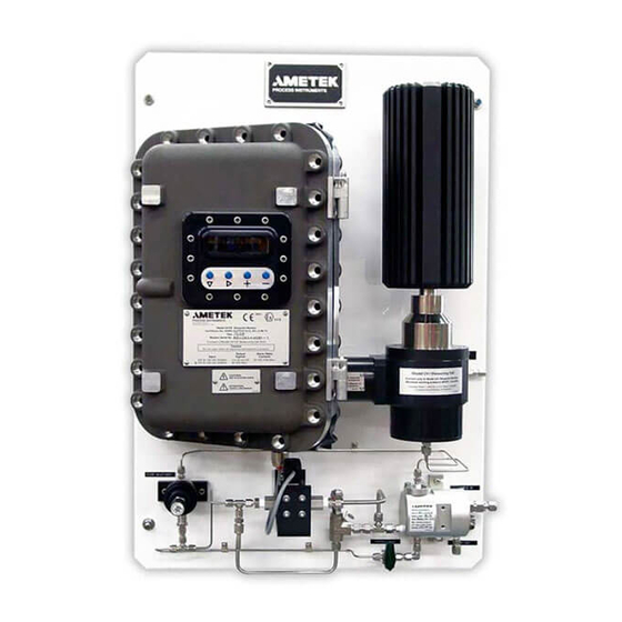
Vent Lines are all provided on the backpan (Figure 1-1). The remain- ing components of the sample system – Sample Line, Sample Probe, Vent Line to a low pressure flare header (or vent to atmosphere) – can be sup- plied by AMETEK or provided by the customer. Figure 1-1. Sample system component layout. -
Page 20: Sample Path
Probe. In the Sample Probe (Figure 1-2), the sample gas passes through an isolation valve and into the Sample Line which carries it to the Filterblock Assembly. Figure 1-2. Gas flow schematic. 1-4 | Model 241CE II Hydrocarbon Dewpoint Analyzer... - Page 21 Figure 1-3. Measuring Cell Assembly, cutaway view. Overview...
- Page 22 ELECTRONICS ENCLOSURE DISPLAY & PUSH-BUTTONS ANALOG OUTPUTS MICROCONTROLLER LOGIC POWER POWER SUPPLY SUPPLY ASSEMBLY MIRROR SAMPLING VALVE PHOTO- LEDS TRANSISTOR Figure 1-4. Logic diagram. MEASURING CELL ASSEMBLY 1-6 | Model 241CE II Hydrocarbon Dewpoint Analyzer...
- Page 23 From the Filterblock Assembly, the gas passes through a Flow Restric- tor and then through a flame arrestor before entering the Measuring Cell, where the sample is measured using the chilled-mirror technique. It then leaves the Cell and passes through another flame arrestor, a pres- sure regulator, and a 1 PSIG check valve on its way back to the Filterblock Assembly and then to the Vent Line, which vents the used sample gas to atmosphere or to an approved low pressure (<50 PSIG) flare header.
- Page 24 Warming Stage, the Heatsink serves as a passive source of heat by using the surrounding ambient temperature to heat the mirror. Optical Systems The Model 241CE II Analyzer employs two Optical Systems in its Measuring Cell: • One detects hydrocarbon condensation on the rough, black surface.
-
Page 25: Working In This Manual
These reminders indicate related information about the topic, certain actions that See also “Troubleshooting are necessary before continuing with the current procedure, or information that and Diagnostics” in Chapter 5. is recommended by AMETEK. User Interface Navigation icon: ... -
Page 26: Supplemental Information - Where Can I Find It
(e.g., “AB-241-S1234-5”). If these drawings are not included, use the drawings in the manual. Other customer-specific information may also be included (if ap- plicable), such as Product Data Sheets, a Custom Spare Parts list, or analyzer Certificates. 1-10 | Model 241CE II Hydrocarbon Dewpoint Analyzer... -
Page 27: Chapter 2 Specifications
SPECIFICATIONS These performance characteristics are based on operation with factory-set configuration parameters. Standard Ranges For application of sweet (H S < 50 PPM) natural gas. The composition of the gas must be above the upper explosive limit. Methodology Chilled-mirror technique. Speed of Response 2 °C per minute (typical cooling rate), with cycle time typically 20–30 minutes. -
Page 28: Sensitivity
System 200 Configurator Software installed on a laptop computer. Electrical Requirements Power Consumption < 275 W Maximum Current: Supply Voltage 120 VAC, 50/60 Hz, ±10 % max. 240 VAC, 50/60 Hz, ±10 % max. 2-2 | Model 241CE II Hydrocarbon Dewpoint Analyzer... -
Page 29: Typical Sample Gas Flow Rate
Typical Sample Gas Flow Rate Variable with line pressure. Typically 1.0–5.0 L/min (2.1–10.6 SCFH) dur- ing the Purging/Hold Stage, and 0.3–3.3 Nl/min (0.7–7.0 SCFH) during the remainder of the cycle. The gas purge flow rate during the Purging/Hold Stage must be high enough to completely purge the sample system and Measuring Cell within the allotted Purge time. -
Page 30: Environmental
- 75 mm (3") top and bottom - 900 mm (36") front Door Swing To allow for full door swing, minimum clearance in front of the analyzer is approximately 574 mm (22.6"). 2-4 | Model 241CE II Hydrocarbon Dewpoint Analyzer... -
Page 31: Dry Gas Supply (Purge Air)
1 PSIG (70 mBAR). (Dry gas supplied by the cus- tomer/end user.) Before operating the Model 241CE II Analyzer, a Flame Arrestor Fit- ting must be installed on the Cooler Housing (to a dry gas supply). -
Page 32: Atex And Iecex Certificates And Analyzer Markings
For installation sites with potentially explosive atmospheres that require ATEX and IECEx certification, AMETEK’s ATEX and IECEx certificates for the Model 241CE II Analyzer (and their markings) are included in the fol- lowing pages. 2-6 | Model 241CE II Hydrocarbon Dewpoint Analyzer... - Page 33 Specifications...
- Page 34 2-8 | Model 241CE II Hydrocarbon Dewpoint Analyzer...
- Page 35 Specifications...
- Page 36 2-10 | Model 241CE II Hydrocarbon Dewpoint Analyzer...
- Page 37 Specifications 2-11...
- Page 38 2-12 | Model 241CE II Hydrocarbon Dewpoint Analyzer...
- Page 39 ATEX- and IECEx-certified Model 241CE II Analyzers are marked with this label: 0344 II 2 G Model 241CE II Dewpoint Analyzer Certificate Nos.: KEMA 02ATEX2121 X, IECEx DEK12.0052X Ex db IIB T4 Gb Year: _______ Analyzer Serial No.: __________________ Caution Do not open when an explosive gas atmosphere is present.
-
Page 40: Csa Certificate And Analyzer Marking
CLASS – 2258 02 - PROCESS CONTROL EQUIPMENT-For Hazardous Locations- Class I, Division 1, Groups C and D; Ex d IIB T3 (Class I, Zone 1, Group IIB) Dew Point Monitor, Model 241CE and/or Dew Point Analyzer, Model 241CE II, Temperature Code T3C, 0°C to +40°C ambient;... - Page 41 Certificate: 1108925(048179_0_000) Master Contract: 164369 Project: Date Issued: 2015-11-06 70045880 APPLICABLE REQUIREMENTS CSA C22.2 No 0 – 10 - General Requirements - Canadian Electrical Code Part II. CSA C22.2 No 0.4 – 04 - Bonding and Grounding of Electrical Equipment (Protective Grounding). CSA C22.2 No.
- Page 42 ASAP 1760518 March 6, 2006 Update Report 1108925 to include the addition of product name Dew PointAnalyzer, Model 241CE II, optional Optocoupler Relay, and molybdenummaterial for Heat Transfer Plate and Heat Transfer Button History Nov 22, 1996 Original Certification...
- Page 43 CSA-certified Model 241CE I Analyzers are marked with this label: PROCESS INSTRUMENTS Western Research Analyzer Model: 241CE II SN: ________________________ ___120Vac ___240Vac, 50/60 Hz, 275W CLASS I, DIVISION 1 GROUPS C & D CLASS I ZONE 1 Ex d IIB T3C, Tamb. +40°C Output signals: 4-20mA (30VDC Max) Relay Contacts 24VDC 0.5A Max...
- Page 44 This page intentionally left blank. 2-18 | Model 241CE II Hydrocarbon Dewpoint Analyzer...
-
Page 45: Chapter 3 Installation And Start-Up
INSTALLATION and START-UP This chapter describes how to install and start up the Model 241CE II Hydrocarbon Dewpoint Analyzer, including: • Safety requirements to consider before working on the analyzer. • Uncrating, inspecting, and storing the analyzer prior to installation. -
Page 46: Safety Considerations
Recommended storage conditions include: Temperature: -20 °C–60 °C (-4 °F–140 °F) Relative Humidity: maximum 95 %, non-condensing Failure to comply with these storage conditions will void your warranty. 3-2 | Model 241CE II Hydrocarbon Dewpoint Analyzer... -
Page 47: Uncrating And Inspecting The Analyzer
Uncrating and Inspecting the Analyzer The analyzer and its sample system is shipped pre-mounted on a back- pan, either alone in a crate or in a crated weatherproof shelter. Upon receiving the analyzer, remove the shipping crate and check the exterior of the shelter and/or analyzer for damage. -
Page 48: General Installation Information
(breaker) must be connected to and mounted near the analyzer, in an easily accessible area. The switch (breaker) must be clearly labeled (e.g., “AMETEK Model 241CE II Analyzer Main AC Power Disconnect Switch”). For safety reasons during maintenance, this switch allows the main AC power to be disconnected from the analyzer prior to perform- ing service on the analyzer. - Page 49 • Rotameter, to set the sample gas flow rate that will be used during the Purge Stage. This flow rate measuring device can be a permanent installation if the rotameter is rated and approved for the pressure it will be exposed to if the Vent Line is closed off. (Example, if the Vent Line is closed, the rotameter must be able to withstand the pressure of the process line.) If the rotameter being used cannot withstand the process gas line...
-
Page 50: Installing The Mechanical Components
“As-Built” drawings (see Documentation Package), use those drawings. Location and Environment The Model 241CE II Analyzer is designed for indoor operation (Pollution Degree 2). In all cases, the analyzer system must be installed indoors to ensure it is shielded from harsh environmental elements. The entire ana- lyzer system (and its backpan) can be mounted directly on a wall inside a building, in a specially designed cabinet, or in a custom-built shelter. - Page 51 In a suitable location as close as possible to the sample point, install the analyzer in a vibration-free location. For each installation method, AMETEK recommends mounting the analyzer higher than the process pipe, since liquids can occasionally NOTE appear in the process stream and in the Sample Line. This will allow these liquids in the Sample Line to drain back into the process pipe.
- Page 52 Figure 3-1. Analyzer backpan mounting details. 3-8 | Model 241CE II Hydrocarbon Dewpoint Analyzer...
-
Page 53: Installing The Heatsink/Measuring Cell Assembly
Installing the Heatsink/Measuring Cell Assembly Ensure there is no power being supplied to the analyzer during the installation of the Heatsink/Measuring Cell Assembly. WARNING While installing the Heatsink/Measuring Cell Assembly, take care not to damage the joining surfaces (flamepath) of the Housing Seal on the CAUTION Ex Housing and Heatsink/Measuring Cell Assemblies. - Page 54 M6 X 20 HEX SOCKET SCREWS (4 PLACES) TORQUE M6 SCREWS TO 36IN-LBS ±9IN-LBS TO PRESSURE REGULATOR Figure 3-2. Heatsink/Measuring Cell Assembly REFERENCE: KEMA 02ATEX2121X mounting instructions. TO FILTERBLOCK REFERENCE: CSA 1108925 (LR 48179-30) 3-10 | Model 241CE II Hydrocarbon Dewpoint Analyzer...
-
Page 55: Installing The Sample System
Installing the Sample System The analyzer is shipped complete with a Filterblock Assembly, Pressure Regulator, and a Solenoid Valve. Unless specified, the Sample and Vent Line Connection Fittings on the Filterblock Assembly are 1/4" Swagelok ® tubing fittings. Flow restrictors used to control the flow rate of the sample gas and bal- ance the pressure drops within the sample system and Measuring Cell are integrated within the sample system. -
Page 56: Sample System Prerequisites
Sample System Prerequisites The Model 241CE II Analyzer is designed, primarily, to monitor the hydrocarbon dewpoint (HCDP) temperature in sweet (H2S <50 PPM) natural gas streams. The analyzer also monitors the dewpoint temperature of water internally, but this internal water dewpoint (WDP) temperature is used primarily for compensation purposes in the calculation of HCDP measurements. -
Page 57: Installing The Sample Probe
The sample gas pressure must be less than the maximum working pres- sure (MWP) rating of each sample system component. The MWP of the Model 241CE II Analyzer is 13 790 KPA (2000 PSI). Although the analyzer is supplied with a filter to remove particulate and liquid aerosols, the sample gas should not contain more than trace quantities of solid parti- cles, liquid droplets, or waxes. -
Page 58: Installing The Sample And Vent Lines
When operating at very low pressures below 20 BAR (300 PSIG) and with large quantities of liquid droplets present in the gas stream, the NOTE flow through the drain Flow Restrictors in the Filterblock Assembly may be insufficient to remove all liquid. 3-14 | Model 241CE II Hydrocarbon Dewpoint Analyzer... - Page 59 If your system will be operating at these low pressures, AMETEK recommends installing an additional coalescing filter or knock-out pot with an isolation valve or Flow Restrictor (typically supplied by the customer/end user) upstream of the analyzer to provide a constant drain.
-
Page 60: Installing And Connecting The Purge Gas Line
Connect the other end to the fitting on the vent to atmosphere (or low pressure flare header). The standard regulator used on the Model 241CE II Analyzer has an outlet pressure range of 0–690 KPAG (0–100 PSIG or 0–7 BARG). NOTE Adjust the Vent Line pressure close to atmospheric pressure. -
Page 61: Checking The Fuses
Checking the Fuses Verify that the installed fuses are correct for the operating voltage, and compare them to the fuse holders within the Electronics Enclosure (indi- See Fuse Ratings table in Figure 3-3. vidually labeled). At the front of each fuse holder on the upper side is a tab that projects upwards. -
Page 62: Connecting The I/O Signals, Alarm Relay Contacts, And Ac Power
Figure 3-3. AC POWER ANALOG CUSTOMER CONNECTIONS SUPPLY MAINS FUSE RATINGS SELF-POWERED LOOP POWERED REFERENCE: CERTIFICATION NO: CSA CERTIFICATE: 1108925 (LR 48179-30) KEMA 02ATEX2121 X Figure 3-3. Customer connections, Termination board. 3-18 | Model 241CE II Hydrocarbon Dewpoint Analyzer... -
Page 63: Analog Input Terminals
Analog Input Terminals An external water signal (a 4–20 mA input) can be brought in to the ana- lyzer and then displayed as water dewpoint temperature (WDP) or water content (WCT) on the User Interface or designated V/I outputs. To configure the analyzer to accept an external water signal and display it on its User Interface, additional equipment must be installed on the Mi- crocontroller and Termination boards (typically done at the factory). -
Page 64: Analog Output Terminals
Analog Output Terminals Typically, AMETEK provides two self-powered analog outputs which do not require a loop-power supply and are compatible with loop imped- ances of up to 1000 ohms. Additional outputs can be included if specified by the customer (for external Water Dewpoint or Water Content). The two self-powered analog outputs are used for Hydrocarbon Dewpoint (HCDP) Temperature and Operational Status Code. - Page 65 The results presented on the analog output signal channels (displayed on the User Interface) are held constant until new values are determined. Since it is not possible to represent the ‘<’ (less than) symbol on the ana- log signal channels, check the following for clues to determine whether the HCDP temperature is ‘equal to’...
-
Page 66: Alarm Relay Terminals
NO = Normally Open * Applicable only if H2O DP:INT option is enabled from the MonitorCFG menu. ** Applicable only if H2O DP:INT (with water content) option is enabled from the MonitorCFG menu. 3-22 | Model 241CE II Hydrocarbon Dewpoint Analyzer... -
Page 67: Configuring The Hardware For Digital Communication
RS-232 connections and four terminals for RS-485 connections. The various serial port configurations and cabling requirements between a computer or Distributed Control System (DCS) and the analyzer are detailed in a supporting document, the Model 241CE II Analyzer Serial Communication Interface (Modbus) Manual Supplement. Installation and Start-Up... - Page 68 D-connector and terminal strip. Only one type of serial port configuration can be functional at any given time. Serial Communications Configuration Communication Type JP800 JP801 RS-422 NONE RS-485 Line Termination RS-485 Biased High RS-485 Biased Low 3-24 | Model 241CE II Hydrocarbon Dewpoint Analyzer...
-
Page 69: Digital Communication Protocol
From the “Serial Communications Configuration table,” choose the serial interface type from the Communication Type column, then use settings in that row to configure the jumpers and software, and to terminate the communication lines. If you choose RS-485, consider the location of the analyzer on the line. When the analyzer is used on the end of the communication line, use the End-of-Line (Line Termination) serial interface type. -
Page 70: Ac Power Connections
(breaker) must be connected to and mounted near the analyzer, in an easily accessible area. The switch (breaker) must be clearly labeled (e.g., “AMETEK Model 241CE II Analyzer Main AC Power Disconnect Switch”). For safety reasons during maintenance, this switch allows the main... -
Page 71: North American Installation
Power Cable Entry on the top of the Electronics Enclosure (Figure 3-1). Each unused cable entry port must be plugged with a certified Ex d plug. The plugs are supplied by AMETEK. Do not replace these WARNING plugs with uncertified plugs. -
Page 72: Start-Up And Verification
AMETEK if there is any doubt about the integrity of any flamepath. Powering Up the Model 241CE II Analyzer When the Model 241CE II Analyzer is turned on, the hardware is initial- ized and the configuration data is retrieved from the EEPROM. This information is pre-programmed at the factory, according to pre-arranged customer requirements. -
Page 73: Displayed Signals (Run Menu Scroll Sequence - Quick Reference)
Displayed Signals (RUN Menu Scroll Sequence – Quick Reference) Detailed information about the signals that are displayed on the User Interface can be found in Chapter 4 (see “RUN Menu”). NOTE The RUN menu scrolls automatically and displays, continually, in the fol- lowing order: Displayed Abbreviation... -
Page 74: About The Measuring Cycle
FRate and SRate. This dewpoint is also the switch-point between the Warming and Purging/ Hold Stages. If you change the temperature parameter, carefully consider the stability of the HCDP in the process gas line. 3-30 | Model 241CE II Hydrocarbon Dewpoint Analyzer... -
Page 75: Purging/Hold Stage
Purging/Hold Stage The measuring cycle begins with the Purging/Hold Stage. The Purging operation occurs first, followed by the Hold portion of this stage. While Purging, the solenoid valve is opened to allow sample gas to flow through the Sample Line and Measuring Cell. While sample gas is flow- ing, the mirror temperature stabilizes at its High setpoint temperature. - Page 76 High setpoint temperature of the mirror is minimal. When this occurs, the Cool- ing Stage is initiated and the Stage-Time-Out (“w TimeOut”) SCode and Purging/Hold-Stage-Time-Out (“w Hold TimeOut”) XSCode are generated. 3-32 | Model 241CE II Hydrocarbon Dewpoint Analyzer...
-
Page 77: Cooling Stage
Slow Cooling Rate [SRate, default = 2 °C (3.6 °F)] per minute – to its Low setpoint temperature, typically -30 °C (-22 °F). AMETEK does not recommend changing the Slow Cooling Rate (SRate). This rate was tested at the factory for optimum HCDP dew- CAUTION point sensitivity. - Page 78 User Interface are turned On. If the alarm is a Fault Alarm, the alphanu- meric display on the User Interface will also flash. The SCode is deter- mined by the built-in diagnostics function. 3-34 | Model 241CE II Hydrocarbon Dewpoint Analyzer...
-
Page 79: Warming Stage
Warming Stage The Warming Stage begins immediately after the Cooling Stage ends. The new HCDP temperature – obtained during the Cooling Stage – is displayed on the User Interface. During this stage, the power applied to the Thermoelectric Cooler is reduced stepwise to zero to allow the mirror temperature to increase at a controlled rate of approximately 10 °C/minute (18 °F/minute). -
Page 80: Sample System Leak Check
Flamepaths” in Chapter 6. Replace parts immediately if damage or wear is apparent. Contact AMETEK if there is any doubt about the integrity of any flamepath. Do not exceed the maximum working pressure rating of the sample system – 13.8 MPa (2000 PSIG) – under any circumstances. - Page 81 After all piping and electrical connections have been made, and with the analyzer powered down: 1. Close the Sample Line isolation valve at the process pipe. Close the Vent Line isolation valve at the vent location (or cap the Vent Line). Before applying any pressure to the sample system (from the process), visually and physically check all plumbing connections.
-
Page 82: Adjusting The Sample Gas Flow Rate
(approximately one-tenth of the purge cycle flow). This bypass flow tends to improve accuracy and response time because there is always a small, but constant flow of sample gas flowing through the sample sys- tem and Measuring Cell. 3-38 | Model 241CE II Hydrocarbon Dewpoint Analyzer... - Page 83 For most applications, AMETEK recommends that the analyzer be operat- ed with the Bypass Valve open, although applications with measurements at pipeline pressures of 700 KPAG (100 PSIG) or less should be made with the Bypass Valve closed. During the measuring cycle, the lower flow will create pressure decreases throughout the sample system.
-
Page 84: Sample System Volume And Flow Rates
Do not exceed the pressure rating of the flow metering device. WARNING Sample Gas Absolute Pressure Suggested Maximum Purge Flow Rate L/min SCFH 2000 3000 4000 5000 7500 1088 10000 1450 13790 2000 10.0 3-40 | Model 241CE II Hydrocarbon Dewpoint Analyzer... -
Page 85: Normal Operation
To set the purge flow rate: 1. First, determine the steady-state flow through the Flow Restrictors in the Filterblock. 2. Close the pressure regulator. 3. Adjust the pressure regulator for the lowest flow rate (turn counter- clockwise as far as possible) before reading the flow rate on the flow meter. -
Page 86: Analyzer Configuration
If necessary, see the original configu- ration sheets to revert the analyzer back to its original settings. The Model 241CE II Analyzer is pre-configured at the factory, ac- cording to predetermined and agreed upon customer requirements. NOTE However, if changes are required, most parameters can be changed. -
Page 87: Chapter 4 User Interface
USER INTERFACE This chapter contains information about the following topics: • An introduction to the User Interface. • How to work from the User Interface and navigate through the vari- ous screens. • How to view alarm data, configure analyzer data, configure analyzer settings, and perform analyzer functions. -
Page 88: Introduction To The User Interface
Code (SCode). To change an operating parameter, it must be active on the display. The display line flashes when the Model 241CE II Analyzer is in Standby Mode (a Fault alarm is present). The LEDs provide a visual indicator of the built-in diagnostics function. - Page 89 Diagnostics Fault Alarm: Analyzer in Standby Mode – Immediate Service Required (review SCode and XSCode in the Stat\History menu to gather information before contacting AMETEK). The alphanumeric display will also flash to alert the operator to this condition. Diagnostics Warning Alarm: Analyzer reporting an abnormal condition –...
- Page 90 “Save AppCFG?”). • To disable the Off-Spec Alarm from the Stat\History menu if the Off-Spec Alarm is currently enabled (when “En\Dis Alarm?” is displayed). • As part of a password. 4-4 | Model 241CE II Hydrocarbon Dewpoint Analyzer...
-
Page 91: Navigating From The User Interface
Navigating From the User Interface While working from the User Interface, there are four modes of operation that you can access to view or change system information, parameters, or variables. While working from the User Interface, the following rules apply: •... -
Page 92: About Appliccfg And Monitorcfg Passwords
Pressing ‘+’ will cause the new password to be saved to the EEPROM; NOTE the old password will be lost. If the new password is not saved, the pre- vious password will be used following a system reset or power-up. 4-6 | Model 241CE II Hydrocarbon Dewpoint Analyzer... -
Page 93: Working In The Different Menus
Working in the Different Menus While working from the User Interface, there are four main modes (menus) of operation. Press to scroll through the Main Menu items. Viewing and entering data is done using the push-buttons for all menus and sub-menus, which are described in the following pages. -
Page 94: Run Menu Parameters Defined
The current Mirror temperature, displayed in °C or °F. The MTemp value will change on subsequent scroll cycles as the mir- ror temperature stabilizes to the value that has been entered for its High setpoint temperature. 4-8 | Model 241CE II Hydrocarbon Dewpoint Analyzer... - Page 95 Displayed Abbreviation Description WMir The current phototransistor signal from the water side of the mirror (the unit of light reflected from the mirror surface). During the analyzer’s first Purge cycle (Purging/Hold Stage) after a power-up, this value will be at its baseline level because there are no liquids on the mirror.
-
Page 96: Interpreting The Parameter Results And Symbols Displayed On The User Interface
• View the SCode and XSCode (Stat\History menu) for HCDP-related alarms. • If necessary, view the HCDPA sub-menu item (ApplicCFG menu) to view the current setpoint for the HCDP temperature Off-Spec Alarm. 4-10 | Model 241CE II Hydrocarbon Dewpoint Analyzer... -
Page 97: Validating The Current Results
At any given time, the Hydrocarbon Dewpoint (HCDP) value presented on the analog signal channel and displayed on the User Interface is the value determined during the previous Cooling Stage. SCode is updated at the end of each measuring cycle stage and MTemp is always the cur- rent value. -
Page 98: Working In The Status\History Menu
‘+’ or ‘–’ button. If the decoded status bit is clear (i.e., no alarms are present) “OK” is displayed. Otherwise, the corresponding status message is displayed. The possible causes of the status bits are described under SCode and XSCode, in the following descriptions. 4-12 | Model 241CE II Hydrocarbon Dewpoint Analyzer... - Page 99 The Stat\History menu items (listed in their viewing order) and their de- scriptions are: Sub-Menu Item Description En\Dis Alrm? This prompt asks if you wish to enable\disable the out-of-specification (Off-Spec) alarm. To enable the Off-Spec Alarm, press ‘+’. To disable the Off-Spec Alarm, press ‘–’. Clear Alarm? This prompt asks if you wish to clear (reset) all current alarms (Off-Spec or SCode).
- Page 100 EEPROM (changes to the system configuration settings). 000000000-1 This system status parameter displays the Serial Number of the analyzer. M241 Vx-xx This system status parameter displays the current Firmware Version running the Model 241CE II Analyzer. 4-14 | Model 241CE II Hydrocarbon Dewpoint Analyzer...
-
Page 101: Working In The Application Configuration Menu
LED #5 on the User Interface is turned On. Note: This signal will only be displayed if the H2O DP:INT option (plus water con- tent) is enabled from the MonitorCFG menu. AMETEK does not recommend enabling this except for diagnostic purposes only. - Page 102 This parameter allows you to select the Network communications type. Options include: • S2K = System 2000 (Communicating via System 200 Configurator Software). For details about using this software to communicate with the analyzer, refer to the Model 241CE II Analyzer System 200 Configurator Software “User’s Guide” shipped with your system.
- Page 103 Sub-Menu Item Description MB Addr z Modbus slave address, used to select a port that will allow communications between a computer and the analyzer, where ‘z’ is a number between 0–250. The definitions include: Address Definition Disable Modbus interface. 1–127 Enable Modbus interface on RS-232 port.
-
Page 104: Working In The Configuration Menu
IMPORTANT Do not change parameters marked ‘*’ (under “Description”) unless NOTE instructed to do so by an AMETEK service representative. Doing so will result in incorrect measurements and readings. Sub-Menu Item Description This prompt asks to enter Passcode2 to access the MonitorCFG menu (the factory default password Passcode2? is ‘- - - -’). - Page 105 * Water mirror surface LED brightness level, where ‘n’ = the LED level. This level can be any value between 0–4095, which represents a drive-current range of 0–50 mA. Do not adjust this value un- less instructed to do so by an AMETEK Service Representative. Note: This signal is derived from the Water-side mirror LED within the analyzer’s...
- Page 106 * Hydrocarbon detection second (high) trigger level, where ‘n’ = the current trigger level threshold. This variable allows you to specify the high threshold of the increasing hydrocarbon phototransistor signal. Do not adjust this value unless instructed to do so by an AMETEK Service Representa- tive.
- Page 107 Sub-Menu Item Description V/I Analog output #3 Zero calibration value, WCT (4.00 mA). Note: This parameter will be displayed only if an external water signal is provided and if the H2O CT:EXT option is enabled from the MonitorCFG menu. V/I Analog output #3 Span calibration value, WCT (20.00 mA). Note: This parameter will be displayed only if an external water signal is provided and if the H2O CT:EXT option is enabled from the MonitorCFG menu.
-
Page 108: Current Output Zero/Span Calibration
Fault Alarm relay. During this condition, the diagnostics function places the analyzer in Standby Mode; the analyzer requires immediate service. For more information about this condition, refer to Chapter 6. 4-22 | Model 241CE II Hydrocarbon Dewpoint Analyzer... -
Page 109: Chapter 5 Functional Verification
FUNCTIONAL VERIFICATION Since the analyzer operation is based on first principles, analyzer calibra- tion is not required. This is fortunate because the preparation of a high- pressure gas mixture with a known and stable dewpoint temperature is extremely difficult. If a mixture is prepared and stored in a tank, the dewpoint temperature can change as the gas is consumed. - Page 110 Pressure of Propane tables (Figures 5-1 and 5-2). NOTE The pressure on the gauge must be set at “gauge” pressure not “abso- lute” pressure. To determine gauge pressure, subtract the barometric pressure from the absolute pressure. 5-2 | Model 241CE II Hydrocarbon Dewpoint Analyzer...
- Page 111 6. When the flushing is complete, reset the MTLo to a temperature below the propane’s dewpoint temperature. This allows the analyzer to proceed through a proper measuring cycle. Once the purging time (Purge) has elapsed and the solenoid valve has closed – prior to the RUN Mode...
-
Page 112: Propane Vapour Pressure
Pv is the vapour pressure propane (mm Hg) and T is the absolute temperature (K). Equation 2 was based upon 105 data points in the range -128.9 to 96.8 °C and fitted the data with an average deviation of 0.46 per- cent. 5-4 | Model 241CE II Hydrocarbon Dewpoint Analyzer... - Page 113 Vapour Pressure (KPA) Vapour Pressure (PSIA) Average Average (°C) Ref. 1 Ref. 2 Ref. 3 (°F) Ref. 2 Ref.3 Ref. 2 & 3 Ref. 2 & 3 -56.6 50.662 50.78 51.01 50.89 -69.9 7.37 7.40 7.38 -55.6 53.329 53.46 53.69 53.57 -68.1 7.75...
-
Page 114: References
Norman Adolph Lange and Gordon M. Forker (eds.), Handbook of Chemistry (Revised tenth edition), (New York, N.Y.: McGraw-Hill, Inc., 1967). Carl C. Yaws, “Physical & Thermodynamic Properties – Part 24: Correlation constants for chemical compounds”, Chemical Engineering, November 22 (1976)153-62. 5-6 | Model 241CE II Hydrocarbon Dewpoint Analyzer... -
Page 115: Chapter 6 Maintenance And Troubleshooting
MAINTENANCE and TROUBLESHOOTING This chapter contains information about the following topics: • Preventive maintenance to keep the Model 241CE II Analyzer operat- ing at peak efficiency. • Cleaning integral, internal parts that make up the sample system. • Changing out replaceable parts. -
Page 116: Preventive Maintenance
Preventive Maintenance Schedule. To reduce the occurrence of problems with the analyzer, AMETEK recom- mends that you follow the Preventive Maintenance Schedule. Since the Measuring Cell is the component that is most susceptible to problems, such as contamination, the primary objective of the Preventive Mainte- nance Schedule is proper care of the Measuring Cell Assembly. - Page 117 If the analyzer is repeatedly generating alarms that may indicate a faulty Peltier Cooler or RTD, AMETEK suggests returning the assembly to the factory for repair. Alarm messages that may indicate the Thermoelectric Cooler or RTD show signs of being unable to cool down or warm up the mirror include: •...
-
Page 118: Analyzer Preventive Maintenance Schedule
Replace the o-rings and Flow Restrictors if they cannot be re-used. (Typically, the recommended replacement of these parts is annually unless they are damaged or contaminated.) See also “Cleaning and Replacing Parts in the Filterblock Assembly” in this chapter. 6-4 | Model 241CE II Hydrocarbon Dewpoint Analyzer... - Page 119 During each analyzer maintenance, use a feeler gauge to check the flamepath gap of the Electronics Enclosure flanges (enclosure door and housing joining surfaces). The gap must not exceed 0.08 mm; if the gap exceeds this value, contact AMETEK for advice. See “Examining and Caring For the Flamepaths” in this chapter.
-
Page 120: Changing Out Replaceable Parts
For tools and supplies required to replace the Sample/Vent Lines, see “Tools, Equipment, and Supplies Required” in Chapter 3. If cleaning is required, use Isopropanol or another similar non-abrasive cleaning agent. 6-6 | Model 241CE II Hydrocarbon Dewpoint Analyzer... - Page 121 To clean or replace the Sample and Vent Lines: 1. Bleed down the sample system. To do this, close the isolation valve on the Sample Probe or at the Sample Inlet valve. Open the Bypass Valve, if not already done, and allow the gas pressure in the sample system and Measuring Cell to depressurize for approximately 5 minutes.
- Page 122 Typically, five measuring cycles will be sufficient to remove the water or air contaminants after the sample system has been exposed to water or the atmosphere. 6-8 | Model 241CE II Hydrocarbon Dewpoint Analyzer...
-
Page 123: Measuring Cell Maintenance
Measuring Cell Maintenance See Figure 6-1 while disassembling the Measuring Cell to clean it and/or replace its o-ring. Clean the Measuring Cell: • Every 6 months. • If one or more of the following Status Codes (SCodes) are displayed: - w Dirty Cell (SCode 16) RUN Mode... - Page 124 INDEXED MIRROR ASSEMBLY (300-4499) (100-2653) RTD OPENING APPLY THERMAL COTE TO SURFACE (300-4477) OPTO-RING PWB FLEX BOARD OPTO-RING ASSEMBLY (100-1184) O-RING, EPR-218 (300-4511) SAMPLE CELL ASSEMBLY (100-2652) Figure 6-1. Measuring Cell Assembly. 6-10 | Model 241CE II Hydrocarbon Dewpoint Analyzer...
- Page 125 Before beginning, read the following Caution and Warnings: Turning off the power deactivates the solenoid valve in the closed posi- tion. CAUTION The Cooler Housing-to-Seal (on the Electronics Enclosure) and Heat- sink Mounting Sleeve are flamepath areas. Take special care to avoid CAUTION scratching, indenting, or otherwise damaging these joining surfaces.
- Page 126 Do not separate the Heatsink from the Cooler Housing unless it is necessary to inspect the Peltier Cooler or RTD in the Cooler Housing, CAUTION and only if instructed to do so by your AMETEK representative. 6-12 | Model 241CE II Hydrocarbon Dewpoint Analyzer...
- Page 127 • If the Measuring Cell Assembly cannot be cleaned in place, remove the Measuring Cell Assembly (including the Cooler Housing/Heat- sink Assembly) from the Electronics Enclosure. To do this, first disconnect the Purge Air Connection from the Cooler Housing. Next, remove the (4) M6 x 20 screws that secure the Cooler Hous- ing to the Electronics Enclosure.
- Page 128 Inspect the o-ring for damage, such as nicks, cuts, or scratches. Typi- cally, AMETEK recommends replacing the o-ring annually, or any time the Measuring Cell is disassembled. The mirror support is an epoxy resin, the optic-path windows are...
- Page 129 Flush and rinse these components with Isopropanol and then allow them to air-dry thoroughly. To quicken the drying process, apply a continuous flow of dry pres- surized gas (e.g., air, nitrogen, carbon dioxide, or helium) through the NOTE flame arrestors. This will force out any remaining Isopropanol in the flame arrestors and thoroughly dry the components.
- Page 130 Typically, five measuring cycles will be sufficient to remove the water or air contaminants after the sample system has been exposed to water or the atmosphere. 6-16 | Model 241CE II Hydrocarbon Dewpoint Analyzer...
-
Page 131: Filterblock Maintenance
Filterblock Maintenance The Membrane Filters in the Filterblock Assembly should be inspected periodically for signs of contamination or damage. Clean the Filterblock: • If alarms that indicate the optical paths show signs of contamination are displayed, such as: RUN Mode Stat\HistorySCode - f H2O Optics (SCode 32) - f HC Optics (SCode 64) - Page 132 Figure 6-2. Filterblock Assembly. 6-18 | Model 241CE II Hydrocarbon Dewpoint Analyzer...
- Page 133 “P/N” refers to Part Number. NOTE To clean and replace parts in the Filterblock (see Figure 6-2): Hazardous Locations Before proceeding, test the area around the analyzer for explosive WARNING gases and proceed only when the area is found to be safe. Do not open the Electronics En closure, do not connect a serial cable to RS-232 serial port Communications Port, and do not power up/...
- Page 134 1/8" NPT threads. Remove the (3) #008 o-rings, one from each Flow Restrictor. If previous sample gas flow rates suggest possible plugging of the Filterblock Flow Restrictors are plugged, replace them with new ones. NOTE 6-20 | Model 241CE II Hydrocarbon Dewpoint Analyzer...
- Page 135 9. Remove the (3) M6 x 20 screws and remove the Filterblock Core. Inspect the Back Filterblock interior for signs of particulate or waxy films. Remove the M6 nut, Seal Washer, o-rings (#010, #115), and the Filter Cartridge. 10. Clean all metal parts in the assembly – including the Sintered Disks – with a cleaning solvent (Isopropanol or reagent-grade acetone are both acceptable solvents).
- Page 136 Install the (6) M6 x 50 screws and tightening them in a cross-pattern. The torque specification to fasten M6 screws is 4.0 Nm, ±0.7 Nm (36 in.-lb, ±9 in.-lb). 6-22 | Model 241CE II Hydrocarbon Dewpoint Analyzer...
- Page 137 15. Install the Filterblock Assembly on its mounting screws (on the back- pan) and tighten them. 16. Reconnect the tubing to the Filterblock Assembly and hand-tighten the nut for each fitting. Using two wrenches, use one to rotate the nut to the original position (an increase in resistance will be encountered at the original position), then tighten it slightly.
-
Page 138: Examining And Caring For The Flamepaths
Replace the parts immediately if damage or wear is apparent. Contact AMETEK immediately if there is any doubt about the integrity of any flamepath. 6-24 | Model 241CE II Hydrocarbon Dewpoint Analyzer... -
Page 139: Electronics Enclosure Flamepaths (Joining Surfaces)
Electronics Enclosure Flamepaths (Joining Surfaces) Any time the Electronics Enclosure is opened for maintenance, inspect the flamepath (joining surfaces) for scratches, indentations, or other damage. Carefully clean the flamepath with a soft, non-abrasive cloth just prior to closing it. If it is necessary to use a cleaning agent, make sure the AC power to the analyzer is off. -
Page 140: Push-Button And Window Housing Flamepaths
Window Housing for any visible signs of wear, such as color loss on the cylindrical portion of the push-buttons. If the push-buttons show signs of wear or become damaged, contact your AMETEK Service Representa- tive. If the push-buttons become stuck, do not attempt to dislodge them using pliers or any other tools. - Page 141 Figure 6-3. Window/Push-button assembly details. Maintenance and Troubleshooting 6-27...
- Page 142 Window Housing assembly with new parts. Continue with Step 3. If the push-buttons are not damaged or worn, you do not have to remove them – continue with Step 4. NOTE 6-28 | Model 241CE II Hydrocarbon Dewpoint Analyzer...
- Page 143 4. To replace the push-buttons and Window Housing Assembly: a. Remove all of the M10 screws that secure the enclosure door (ana- lyzer housing) to its housing and open the door. b. Take appropriate precautions to avoid causing electrostatic dam- age to the circuit board.
-
Page 144: Window (User Interface)
Periodically, examine the window for scratches, chips, or cracks. Replace the Window Housing assembly if it is damaged. Replace the push-buttons at the same time. Be careful not to scratch the window. Scratches will reduce impact resistance. CAUTION 6-30 | Model 241CE II Hydrocarbon Dewpoint Analyzer... -
Page 145: Troubleshooting And Diagnostics
Troubleshooting and Diagnostics This section describes how the Model 241CE II Analyzer detects and displays alarms associated with its operation, what the alarms mean, and action to take to correct the alarms. This section also discusses how to view the alarms from the User Interface and how to reset the analyzer if a system reset is required. -
Page 146: Types Of Alarms
Measurement results obtained under a Warning alarm condition are usu- ally valid, but if one or more of the serious SCodes are output, the result- ing data may be suspect. Check the SCode and XSCode for symptoms. 6-32 | Model 241CE II Hydrocarbon Dewpoint Analyzer... -
Page 147: Fault Alarms
Fault Alarms Fault alarms indicate that a serious condition has been detected which interferes with proper operation of the analyzer – a failure of an integral part of the system has occurred. When a Fault alarm is present, the alpha- numeric display will flash and LED 2 turns On to alert the operator that immediate attention is required (the analyzer requires service). -
Page 148: Alarm Led Status
(ApplicCFG : HCDPA). This alarm will only be seen if the Off-Spec Alarm is enabled in the Stat\History menu (LED 1 is Off when the Off-Spec Alarm is enabled). User Reserved for Water Dewpoint temperature OffSpec Alarm setpoint. Currently Not Used. 6-34 | Model 241CE II Hydrocarbon Dewpoint Analyzer... -
Page 149: Operating In Standby Mode (Fault Alarm)
Operating in Standby Mode (Fault Alarm) When the detection of the HCDP is improbable, the built-in diagnostic function activates and latches the Fault Alarm relay, turns LED 2 On, and places the analyzer in Standby Mode. While in Standby Mode, the User Interface flashes to alert the operator that immediate attention is required. -
Page 150: Clearing (Resetting) Alarms
LED 1 will turn Off to indicate the Off-Spec Alarm is enabled. To disable the Off-Spec Alarm if it is currently enabled, press the ‘–’ button. LED 1 will turn On to indicate the Off-Spec Alarm is disabled. 6-36 | Model 241CE II Hydrocarbon Dewpoint Analyzer... -
Page 151: Types Of Status Codes
Types of Status Codes There are Status Codes (SCodes) and Extended Status Codes (XSCodes) for a wide variety of events. SCodes are used to inform the operator which particular conditions gave rise to a Warning or Fault alarm. Simi- larly, XSCode is obtained by summing the primary codes of any coexisting conditions. - Page 152 Total sum of all primary SCodes found -256 f H2O Dim [Light-Intensity-On-Water-Side-Is-Too-Low] Remaining sum of all primary SCodes found w High DP [Hydrocarbon-Dewpoint-Temperature-Too-High] Remaining sum of all primary SCodes found w Cool TimeOut [Cooling-Stage-Time-Out] w Hold TimeOut [Purging/Hold-Stage-Time-Out] 6-38 | Model 241CE II Hydrocarbon Dewpoint Analyzer...
-
Page 153: Suggested Corrective Actions
A fault alarm always requires corrective action, even if it is only to reset the alarms. If the problem persists after following these suggestions, contact the nearest AMETEK Service Centre or Distributor, or the AMETEK Canada factory for assistance. -
Page 154: Viewing Current Alarm Messages
SCode message). 4. To back out of either of these screens, press if you wish to view oth- er Stat\History sub-menus, or press to go to another main menu. 6-40 | Model 241CE II Hydrocarbon Dewpoint Analyzer... -
Page 155: Viewing Historical Alarm Messages
Viewing Historical Alarm Messages Alarms that have been reset can be reviewed from the History Buffers in the Stat\History menu. SCode alarms which have been reset are stored in the ^SC History Buffer. XSCode alarms which have been reset are stored in the ^XSC History Buffer. -
Page 156: Status Code (Scode), Alarm Conditions, And Corrective Action
“w Cool TimeOut” alarm. If not, decrease the mirror low setpoint temperature (ApplicCFG : MTLo) and check the HCDP temperature (RUN menu) to see if it is particularly high (e.g., greater than 20 °C/68 °F). 6-42 | Model 241CE II Hydrocarbon Dewpoint Analyzer... - Page 157 Primary Error Alarm Code Code Type Condition / Description / Suggested Corrective Action Warning w No HC DP [Hydrocarbon-Dewpoint-Temperature-Not-Found] The hydrocarbon dewpoint temperature was not determined during the last measuring cycle. LED 4 will be On. Corrective Action: • Review the current XSCode (Stat\History menu) to determine if there has been a “w Cool TimeOut”...
- Page 158 Review and interpret the current XSCode (Stat\History menu) to determine the current alarm conditions. Attempt to correct any alarms. If necessary, contact the nearest AMETEK Service Centre or Distributor, or the AMETEK Canada factory for assistance. Fault f HC Optics [Problem-In-Hydrocarbon-Side-Optical-Path] There is a problem with the hydrocarbon-side optics within the Measuring Cell.
- Page 159 AC POWER SUPPLY MAINS ANALOG CUSTOMER CONNECTIONS FUSE RATINGS SELF-POWERED LOOP POWERED REFERENCE: CERTIFICATION NO: CSA CERTIFICATE: 1108925 (LR 48179-30) KEMA 02ATEX2121 X Figure 6-4. Fuse ratings/locations, Termination board (Electronics Enclosure). Maintenance and Troubleshooting 6-45...
-
Page 160: Extended Status Code (Xscode), Alarm Conditions, And Corrective Action
EEPROM. Alternatively, you can send the configuration values and P.O. number for the EEPROM to AMETEK at the same time. At the factory, AMETEK will program the customer- specific parameters in the EEPROM. In this case, you will only have to install the EEPROM;... - Page 161 Primary Error Alarm Code Code Type Condition / Description / Suggested Corrective Action Warning w Hold TimeOut [Purging/Hold-Stage-Time-Out] The analyzer has encountered a problem during the Purging/ Hold Stage of the measuring cycle, such as the mirror temperature at the end of the Purging/Hold Stage is less than the MTHi setting.
- Page 162 "H2O DP:INT (with water content settings adjusted accordingly) and then viewing the WCt value from the RUN menu. If the internal Water Content is very high, this Problem may reduce the HCDP temperature accuracy. 6-48 | Model 241CE II Hydrocarbon Dewpoint Analyzer...
- Page 163 These alarms indicate problems with the RTD (inside the Cooler Housing). Corrective Action: • The RTD may have failed and may need to be replaced. If necessary, contact the nearest AMETEK Service Centre or Distributor, or the AMETEK Canada factory for assistance. Maintenance and Troubleshooting 6-49...
- Page 164 With the Measuring Cell removed, observe the Opto-Ring to check if both LEDs are on. If necessary, contact the nearest AMETEK Service Centre or Distributor, or the AMETEK Canada factory for assistance. 6-50 | Model 241CE II Hydrocarbon Dewpoint Analyzer...
- Page 165 Figure 6-5. Measuring Cell Assembly components. Maintenance and Troubleshooting 6-51...
- Page 166 Figure 6-6. Measuring Cell Assembly, cutaway view. 6-52 | Model 241CE II Hydrocarbon Dewpoint Analyzer...
-
Page 167: If Incorrect Information Is Displayed On The User Interface
If Incorrect Information is Displayed on the User Interface … If the User Interface displays information that is incorrect, it may be due to incorrectly set units of measurement. Check the Options code sub- menu to ensure the proper units of measurement have been selected. ... -
Page 168: Measurement Interferences
Olefins, Paraffins, and Aromatics) can contaminate the mirror surfaces. The hydrocarbons also interfere with the determination of the hydrocarbon dewpoint temperature, if they are not removed from the Measuring Cell during the Purging/Hold Stage. 6-54 | Model 241CE II Hydrocarbon Dewpoint Analyzer... -
Page 169: Resetting The Model 241Ce Ii Analyzer
Resetting the Model 241CE II Analyzer Whenever the analyzer is powered up, the Microcontroller board is reset and the software initialization routine retrieves the configuration data from the EEPROM. When power is restored following a power outage or brown-out (line voltage drops to less than two-thirds of the nominal volt- age), the Microcontroller board will be reset and the analyzer will become operational automatically. - Page 170 This page intentionally left blank. 6-56 | Model 241CE II Hydrocarbon Dewpoint Analyzer...
-
Page 171: Chapter 7 Service And Parts
SERVICE and PARTS This chapter discusses what to do if you need technical support from AMETEK, or if you are returning parts for service. This chapter also lists the recommended spare parts to have on hand to ensure preventive maintenance is performed according to the schedule in Chapter 6. -
Page 172: Returning Equipment
Material Authorization (RMA) number. This will ensure your equip- ment is serviced and returned to you in a prompt and efficient manner. To obtain a RMA number, contact your local or nearest AMETEK Service Centre and have the following information available: •... -
Page 173: Ametek Service And Aftermarket Sales Support
ASAP plans may be written to provide coverage for a single analyzer, or all of the AMETEK • START UPS process analyzers at your facility. Your decision to buy an AMETEK analyzer is greatly •... -
Page 174: Recommended Preventive Maintenance Spare Parts
Recommended Preventive Maintenance Spare Parts This section lists the recommended spare parts to have readily available for the Model 241CE II Analyzer to ensure the analyzer and its sample system operate at peak efficiency. For drawings that illustrate the location of all spare parts in the ana- lyzer, see “Preventive Maintenance”... -
Page 175: Spare Analyzer Fuses
Fuses located on terminal strip (on Termination board) near the top of the Electronics Enclosure (see Fuse rating/locations drawing in Chapter 6). Replacement Boards If you require replacement boards for the Model 241CE II Analyzer, use the following part numbers. Printed Wiring Boards Part No. -
Page 176: Ordering A Hard Copy Of The Analyzer Operator's Guide
(PDF) on a DVD shipped with the analyzer. To order a hard copy of the analyzer Operator's Guide, use the Part Number below: Part No. Description 903-8797 Model 241CE II HCDP Analyzer Operator's Guide 7-6 | Model 241CE II Hydrocarbon Dewpoint Analyzer... -
Page 177: Appendix A - System Options
APPENDIX A – SYSTEM OPTIONS Available options for the Model 241CE II Hydrocarbon Dewpoint Ana- lyzer are: • External Water Dewpoint • External Water Content with Customer Pressure Signal • Self-Powered V/I Outputs • Remote Start When the analyzer is configured to use the External Water Signal op- tion, the Remote Start option is not available. -
Page 178: External Water Dewpoint/Content Option
(U702) on the Microcontroller board. • A 1 %, 249 ohm resistor must be installed across the voltage input Ter- minals (12+) and (13-) on connector J101 of the Termination board. A-2 | Model 241CE II Hydrocarbon Dewpoint Analyzer... -
Page 179: Electrical Connections
Electrical Connections The external water signal to the analyzer must be a 4–20 mA input. To display this signal on the User Interface, connect a 4–20 mA external water signal to the spare analog input Terminals 12+ and 13- on connec- tor J101 on the Termination board in the Ex d Electronics Enclosure. - Page 180 (WCT) reading. Press to refresh the reading by scrolling through the readings until the WDP or WCT reading is displayed again. Record this value for future reference. A-4 | Model 241CE II Hydrocarbon Dewpoint Analyzer...
- Page 181 d. Use the following formulas to calculate a new ExLo and ExHi to compensate for the differences between the input value and the displayed value: A = Range Lo (ExLo range [low output from the external water dewpoint/water content source]) B = Range Hi (ExHi range [high output from the external water dewpoint/water content source]) C = Reading Lo (external water dewpoint/water content reading...
-
Page 182: Remote Start Option
180 minute period by turning off the purge sole- noid using the appropriate Modbus register. For details about the Modbus registers, refer to the Model 241CE II Analyzer Serial Communication Interface (Modbus) Manual Supplement. A-6 | Model 241CE II Hydrocarbon Dewpoint Analyzer... -
Page 183: Appendix B - Drawings
APPENDIX B – DRAWINGS This appendix contains drawings that are not included in the main body of this manual. If your Documentation Package includes optional Final “As-Built” (job-specif ic) drawings, use those for installation and maintenance/ NOTE diagnostic purposes in place of the installation drawings in this manual. -
Page 184: Analyzer Block Diagram (Wx-241Ce
Analyzer Block Diagram (WX-241CE II-1) B-2 | Model 241CE II Hydrocarbon Dewpoint Analyzer... -
Page 185: Digital Communications Wiring Diagram (Wx-241Ce
Digital Communications Wiring Diagram (WX-241CE II-5) Appendix B – Drawings... -
Page 186: Interconnection Diagram (100-2091-13
Interconnection Diagram (100-2091-13) B-4 | Model 241CE II Hydrocarbon Dewpoint Analyzer... -
Page 187: Electrical Block Diagram (100-2091-15
Electrical Block Diagram (100-2091-15) Appendix B – Drawings... -
Page 188: Optional I/O Wiring (100-2091-14
Optional I/O Wiring (100-2091-14) B-6 | Model 241CE II Hydrocarbon Dewpoint Analyzer... -
Page 189: Probe Mounting (Wx-241Ce
Probe Mounting (WX-241CE II-6) Appendix B – Drawings... - Page 190 This page intentionally left blank. B-8 | Model 241CE II Hydrocarbon Dewpoint Analyzer...
-
Page 191: Supplemental Information
• 241_Signed Final QC (Quality Control) Document • 241_Final As-Built drawings (if applicable). Note that these drawings are included only for non-standard Model 241CE II Analyzers. • Other customer-specific information may also be included (if applicable), such as Product Data Sheets, a Custom Spare Parts list, or analyzer Certificates. - Page 192 This page intentionally left blank. S-2 | Model 241CE II Hydrocarbon Dewpoint Analyzer...
Need help?
Do you have a question about the 241CE II and is the answer not in the manual?
Questions and answers