Sign In
Upload
Manuals
Brands
Ametek Manuals
Measuring Instruments
241CE II
Ametek 241CE II Manuals
Manuals and User Guides for Ametek 241CE II. We have
2
Ametek 241CE II manuals available for free PDF download: Operator's Manual, User Manual
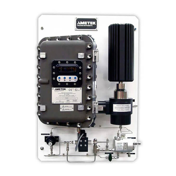
Ametek 241CE II Operator's Manual (192 pages)
Hydrocarbon Dewpoint Analyzer
Brand:
Ametek
| Category:
Measuring Instruments
| Size: 11.14 MB
Table of Contents
Offices
2
Table of Contents
3
Electrical Safety
7
Grounding
7
Safety Notes
7
Personnel and Equipment Safety Information
8
Warnings
8
Cautions
9
Warning Labels
10
Environmental Information
10
Electromagnetic Compatibility (EMC)
11
Special Warnings and Information
12
Equipment Used in Hazardous Locations
12
EU Declaration of Conformity
13
Warranty and Claims
15
Chapter 1 Overview
17
Application
18
About the Analyzer Sample System and Electronics
19
Sample Path
20
Working in this Manual
25
Supplemental Information - Where Can I Find It
26
Chapter 2 Specifications
27
Standard Ranges
27
Methodology
27
Speed of Response
27
Accuracy
27
Repeatability
27
Sensitivity
28
Maximum Water Content
28
Customer Connections
28
Analog Outputs
28
Digital Communication
28
Electrical Requirements
28
Power Consumption
28
Supply Voltage
28
Typical Sample Gas Flow Rate
29
Ambient Temperature
29
Sample Transport
29
Instrument Air
29
Physical Dimensions
29
Maximum Working Pressure
29
Highest Measurable Dewpoint
29
Environmental
30
Humidity
30
Maximum Altitude
30
Cooling Capability
30
Minimum Clearances
30
Dry Gas Supply (Purge Air)
31
Approvals and Certifications
31
ATEX and Iecex Certificates and Analyzer Markings
32
CSA Certificate and Analyzer Marking
40
Chapter 3 Installation and Start-Up
45
Safety Considerations
46
Pre-Installation Requirements
46
Storage Prior to Installation
46
Uncrating and Inspecting the Analyzer
47
General Installation Information
48
Tools, Equipment, and Supplies Required
48
Installing the Mechanical Components
50
Installing the Analyzer
50
Location and Environment
50
Installing the Heatsink/Measuring Cell Assembly
53
Installing the Sample System
55
Sample System Prerequisites
56
Installing the Sample Probe
57
Installing the Sample and Vent Lines
58
Installing and Connecting the Purge Gas Line
60
Checking the Fuses
61
Connecting the I/O Signals, Alarm Relay Contacts, and AC Power
62
Analog Input Terminals
63
Analog Output Terminals
64
Alarm Relay Terminals
66
Configuring the Hardware for Digital Communication
67
Digital Communication Protocol
69
AC Power Connections
70
European Installation
71
North American Installation
71
Start-Up and Verification
72
Powering up the Model 241CE II Analyzer
72
Displayed Signals (RUN Menu Scroll Sequence - Quick Reference)
73
About the Measuring Cycle
74
Purging/Hold Stage
75
Cooling Stage
77
Warming Stage
79
Sample System Leak Check
80
Adjusting the Sample Gas Flow Rate
82
Sample System Volume and Flow Rates
84
Normal Operation
85
Analyzer Configuration
86
Chapter 4 User Interface
87
Introduction to the User Interface
88
Navigating from the User Interface
91
About Appliccfg and Monitorcfg Passwords
92
Working in the Different Menus
93
Working in the RUN Menu
93
RUN Menu Parameters Defined
94
Interpreting the Parameter Results and Symbols Displayed on the User Interface
96
Validating the Current Results
97
Viewing Previous Results
97
Working in the Status\History Menu
98
Working in the Application Configuration Menu
101
Working in the Configuration Menu
104
Current Output Zero/Span Calibration
108
Operating in Standby Mode
108
Chapter 5 Functional Verification
109
Propane Vapour Pressure
112
References
114
Chapter 6 Maintenance and Troubleshooting
115
Safety Considerations
115
Preventive Maintenance
116
Analyzer Preventive Maintenance Schedule
118
Changing out Replaceable Parts
120
Cleaning or Replacing the Sample and Vent Lines
120
Measuring Cell Maintenance
123
Filterblock Maintenance
131
Examining and Caring for the Flamepaths
138
Electronics Enclosure Flamepaths (Joining Surfaces)
139
Push-Button and Window Housing Flamepaths
140
Window (User Interface)
144
Troubleshooting and Diagnostics
145
About Alarms and Status Codes
145
Types of Alarms
146
Warning Alarms
146
Fault Alarms
147
Off-Spec Alarms
147
Alarm LED Status
148
Operating in Standby Mode (Fault Alarm)
149
Clearing (Resetting) Alarms
150
Enabling/Disabling the Off-Spec Alarm
150
Interpreting Status Codes and Extended Status Codes
151
Types of Status Codes
151
Suggested Corrective Actions
153
Viewing Current Alarm Messages
154
Viewing Historical Alarm Messages
155
Status Code (Scode), Alarm Conditions, and Corrective Action
156
Extended Status Code (Xscode), Alarm Conditions, and Corrective Action
160
If Incorrect Information Is Displayed on the User Interface
167
Measurement Interferences
168
Resetting the Model 241CE II Analyzer
169
Chapter 7 Service and Parts
171
Technical Support
171
Returning Equipment
172
AMETEK SERVICE and AFTERMARKET SALES SUPPORT
173
Recommended Preventive Maintenance Spare Parts
174
Model 241CE II Analyzer (120 / 240 VAC) Spare Parts
174
Spare Analyzer Fuses
175
Replacement Boards
175
Ordering a Hard Copy of the Analyzer Operator's Guide
176
Appendix A - System Options
177
External Water Dewpoint/Content Option
178
Equipment Installation
178
Electrical Connections
179
Calibrating the Voltage Input
179
Remote Start Option
182
Appendix B - Drawings
183
Analyzer Block Diagram (WX-241CE
184
Digital Communications Wiring Diagram (WX-241CE
185
Interconnection Diagram (100-2091-13
186
Electrical Block Diagram (100-2091-15
187
Optional I/O Wiring (100-2091-14
188
Probe Mounting (WX-241CE
189
Supplemental Information
191
Advertisement
Ametek 241CE II User Manual (171 pages)
Hydrocarbon Dewpoint Analyzer
Brand:
Ametek
| Category:
Measuring Instruments
| Size: 9.75 MB
Table of Contents
Table of Contents
3
Safety Notes
7
Electrical Safety
7
Grounding
7
Personnel and Equipment Safety Information
8
Environmental Information - WEEE
11
Special Warnings and Information
12
Equipment Used in Hazardous Locations
12
Electromagnetic Compatibility (EMC)
13
Overview
15
Application
16
About the Analyzer Sample System and Electronics
17
Sample Path
18
Working in this Manual
23
Supplemental Information - Where Can I Find It
23
Installation and Start-Up
25
Safety Considerations
25
Pre-Installation Requirements
26
Storage Prior to Installation
26
Uncrating and Inspecting the Analyzer
27
General Installation Information
28
Tools, Equipment, and Supplies Required
28
Installing the Mechanical Components
30
Installing the Analyzer
30
Location and Environment
30
Installing the Heatsink/Measuring Cell Assembly
33
Installing the Sample System
35
Sample System Prerequisites
36
Installing the Sample Probe
37
Installing the Sample and Vent Lines
38
Installing and Connecting the Purge Gas Line
40
Checking the Fuses
41
Connecting I/O Signals, Alarm Relay Contacts, and AC Power
42
Analog Input Terminals
43
Analog Output Terminals
44
Alarm Relay Terminals
46
Configuring the Hardware for Digital Communication
47
Digital Communication Protocol
49
AC Power Connections
50
North American Installation
51
European Installation
51
Start-Up and Verification
52
Powering up the 241CE II Analyzer
52
Displayed Signals (RUN Menu Scroll Sequence - Quick Reference)
53
About the Measuring Cycle
54
Purging/Hold Stage
55
Cooling Stage
56
Warming Stage
58
Sample System Leak Check
59
Adjusting the Sample Gas Flow Rate
61
Sample System Volume and Flow Rates
63
Normal Operation
64
Analyzer Configuration
65
User Interface
67
Introduction to the User Interface
67
Navigating from the User Interface
70
About Appliccfg and Monitorcfg Passwords
71
Working in the Different Menus
72
Working in the RUN Menu
72
RUN Menu Parameters Defined
73
Interpreting the Parameter Results and Symbols Displayed on the User Interface
75
Validating the Current Results
76
Viewing Previous Results
76
Working in the Status\History Menu
77
Working in the Application Configuration Menu
80
Working in the Configuration Menu
84
Current Output Zero/Span Calibration
88
Operating in Standby Mode
88
Maintenance and Troubleshooting
89
Safety Considerations
89
Aftermarket Excellence and Long-Term Commitment to Safety and Quality
90
Requesting Technical Support
91
Requesting Authorization to Return Equipment
91
Requesting Analyzer Training
91
Spare Parts Lists
92
241CE II Analyzer (120 / 240 VAC) Spare Parts
92
Spare Analyzer Fuses
93
Replacement Boards
93
Diagnostic Flowcharts
94
Checking Flamepaths and Gaps
95
Checking and Recording Operating Temperatures
95
Checking and Recording the Baseline Settings
96
Fault or Warning Status Conditions
96
Incorrect Information Is Displayed on the User Interface
97
Sheltered Systems
98
Maintenance
99
Cleaning or Replacing the Sample and Vent Lines
99
Measuring Cell Maintenance
102
Filterblock Maintenance
110
Examining and Caring for the Flamepaths
117
Electronics Enclosure Flamepaths (Joining Surfaces)
118
Push-Button and Window Housing Flamepaths
119
Window (User Interface)
123
Troubleshooting and Diagnostics
124
About Alarms and Status Codes
124
Types of Alarms
125
Warning Alarms
125
Fault Alarms
126
Off-Spec Alarms
126
Alarm LED Status
127
Operating in Standby Mode (Fault Alarm)
128
Clearing (Resetting) Alarms
129
Enabling/Disabling the Off-Spec Alarm
129
Types of Status Codes
130
Interpreting Status Codes and Extended Status Codes
130
Suggested Corrective Actions
132
Viewing Current Alarm Messages
133
Viewing Historical Alarm Messages
134
Status Code (Scode), Alarm Conditions, and Corrective Action
135
Extended Status Code (Xscode), Alarm Conditions, and Corrective Action
139
Resetting the 241CE II Analyzer
144
Specifications
145
241CE II Analyzer Approvals and Certifications
148
241CE II Analyzer Atex/Iecex Marking
149
241CE II Analyzer CSA-Certified Marking
149
Functional Verification
151
Propane Vapor Pressure
154
References
156
Appendix A - System Options
157
External Water Dewpoint/Content Option
158
Equipment Installation
158
Electrical Connections
159
Calibrating the Voltage Input
159
Remote Start Option
162
Appendix B - Drawings
163
Analyzer Block Diagram (WX-241CE
164
Digital Communications Wiring Diagram (WX-241CE
165
Interconnection Diagram (100-2091-13
166
Electrical Block Diagram (100-2091-15
167
Optional I/O Wiring (100-2091-14
168
Probe Mounting (WX-241CE
169
Advertisement
Related Products
Ametek Surtronic 25
Ametek Universal Analyzers 275E
Ametek 2850
Ametek 24-1050FR80T
Ametek 24-600FR80T
Ametek 24-750FR80T
Ametek 24-880FR80T
Ametek 24-450FR100T
Ametek 24-750FR100T
Ametek 24-880FR100T
Ametek Categories
Measuring Instruments
Test Equipment
Power Supply
Controller
Laboratory Equipment
More Ametek Manuals
Login
Sign In
OR
Sign in with Facebook
Sign in with Google
Upload manual
Upload from disk
Upload from URL