Sign In
Upload
Download
Table of Contents
Contents
Add to my manuals
Delete from my manuals
Share
URL of this page:
HTML Link:
Bookmark this page
Add
Manual will be automatically added to "My Manuals"
Print this page
×
Bookmark added
×
Added to my manuals
Manuals
Brands
Ametek Manuals
Measuring Instruments
Jofra CTC-1205 A
Reference manual
Ametek Jofra CTC-1205 A Reference Manual
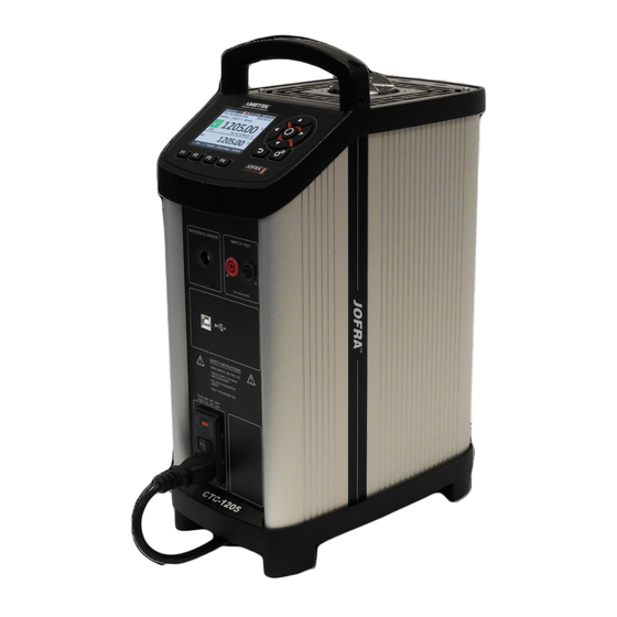
Compact temperature calibrator
Hide thumbs
Also See for Jofra CTC-1205 A
:
User manual
(29 pages)
,
Reference manual
(65 pages)
1
2
3
Table Of Contents
4
5
6
7
8
9
10
11
12
13
14
15
16
17
18
19
20
21
22
23
24
25
26
27
28
29
30
31
32
33
34
35
36
37
38
39
40
41
42
43
44
45
46
47
48
49
50
51
52
53
54
55
56
57
58
59
60
61
62
63
64
65
66
page
of
66
Go
/
66
Contents
Table of Contents
Bookmarks
Table of Contents
Table of Contents
Introduction
Warranty
Receiving the Compact Temperature Calibrator
Dimensioning Drawing
Safety Instructions
Setting up the Calibrator for Use
Preparing the Calibrator
Choosing an Insertion Tube
Standard Insertion Tubes
Inserting the Sensor
External Reference Sensor
Calibrator Interface
Keypad - Functions
Display - Functions
Main Screen Temperature Values
Stability of Temperature Values
Input/Output Connections
Operating the Calibrator
Operating Principle
System Menu
Starting the Calibrator
Selecting a TRUE - Reference Sensor (C-Models Only)
Stability Setting
Selecting the Set-Temperature
Editing the Preset Set-Temperature
Auto Step Function
Running an Auto Step Test
The Calibrator's Auto Step Procedure
Switch Test Function
Running a Switch Test
The Calibrator's Switch Test Procedure
Storing and Transporting the Calibrator
Error Messages (List of Alarms)
Returning the Calibrator for Service
Maintenance
Replacing the Main Fuses
Maintenance Mode
Cleaning
Adjusting and Calibrating the Instrument
Maintenance of STS-Reference Sensor
10.0 Technical Specifications
11.0 List of Accessories
Advertisement
Quick Links
1
Adjusting and Calibrating the Instrument
Download this manual
Reference Manual
Compact Temperature Calibrator
Jofra CTC-155/350/652/660/1205 A/C
Table of
Contents
Previous
Page
Next
Page
1
2
3
4
5
Advertisement
Table of Contents
Need help?
Do you have a question about the Jofra CTC-1205 A and is the answer not in the manual?
Ask a question
Questions and answers
Subscribe to Our Youtube Channel
Related Manuals for Ametek Jofra CTC-1205 A
Test Equipment Ametek Jofra CTC-155 A Reference Manual
Compact temperature calibrator (65 pages)
Measuring Instruments Ametek Jofra CTC-155 A/C User Manual
Compact temperature calibrator (29 pages)
Measuring Instruments Ametek Jofra CTC-350 A/C User Manual
Compact temperature calibrator (29 pages)
Measuring Instruments Ametek Jofra CTC-660 A/C User Manual
Compact temperature calibrator (29 pages)
Measuring Instruments Ametek JOFRA CTC-140 A User Manual
(146 pages)
Measuring Instruments Ametek JOFRA CTC-140 A User Manual
(29 pages)
Measuring Instruments Ametek JOFRA CTC-1200 A User Manual
(29 pages)
Measuring Instruments Ametek c Service Manual
(54 pages)
Measuring Instruments Ametek BROOKFIELD CT3 Operating Instructions Manual
Texture analyzer (64 pages)
Measuring Instruments Ametek Jofra CTC-155 C Reference Manual
Compact temperature calibrator (66 pages)
Measuring Instruments Ametek Jofra CTC-652 C Reference Manual
Compact temperature calibrator (66 pages)
Measuring Instruments Ametek Jofra CTC-660 C Reference Manual
Compact temperature calibrator (66 pages)
Measuring Instruments Ametek Jofra CTC-350 C Reference Manual
Compact temperature calibrator (66 pages)
Measuring Instruments Ametek CEM/Humox User Manual
Moisture in flue gas analyzer (136 pages)
Measuring Instruments Ametek CHATILLON DFIS Series Operating Instructions Manual
Digital force gauges (20 pages)
Measuring Instruments Ametek Thermox CEM/O2 User Manual
Oxygen analyzer (154 pages)
This manual is also suitable for:
Jofra ctc-155 a
Jofra ctc-652 a
Jofra ctc-660 a
Jofra ctc-350 a
Jofra ctc-1205 c
Jofra ctc-155 c
...
Show all
Jofra ctc-652 c
Jofra ctc-660 c
Jofra ctc-350 c
Jofra ctc-155 a/c
Jofra ctc-350 a/c
Jofra ctc-652 a/c
Jofra ctc-660 a/c
Jofra ctc-1205 a/c
Table of Contents
Print
Rename the bookmark
Delete bookmark?
Delete from my manuals?
Login
Sign In
OR
Sign in with Facebook
Sign in with Google
Upload manual
Upload from disk
Upload from URL


Need help?
Do you have a question about the Jofra CTC-1205 A and is the answer not in the manual?
Questions and answers