
Related Manuals for Ametek Land 4200


Summary of Contents for Ametek Land 4200
- Page 1 Model 4200 Dust/Opacity Monitor User Guide Publication Nº 770-026 Language: English Issue 11 05 May 2017 © Land Instruments International, 2017...
- Page 2 IMPORTANT INFORMATION - PLEASE READ Health and Safety Information Read all of the instructions in this booklet - including all the WARNINGS and CAUTIONS - before using this product. If there is any instruction which you do not understand, DO NOT USE THE PRODUCT.
- Page 3 Web: www.landinst.com For further details on all AMETEK Land offices, distributors and representatives, please visit our websites. Return of Damaged Goods IMPORTANT If any item has been damaged in transit, this should be reported to the carrier and to the supplier immediately.
-
Page 5: Table Of Contents
User Guide Model 4200 Dust & Opacity Monitor Contents Unpacking and Checking Unpacking Checking on Receipt Instrument Serial Number Health and Safety Warnings Equipment Operation Power Supply Face and Eye Protection Protective Clothing Symbols Used Theory of Operation Theory Beer-Lambert’s Law System Description The System Keypad Functions... - Page 6 Model 4200 Dust & Opacity Monitor User Guide Calibration 10.1 Calibration Audit 10.2 Linearity Filters 10.3 Method 1 - Clear Path Calibration (Opacity) 10.4 Method 2 - Alternative Re-calibration (Opacity) 10.5 Isokinetic Sampling for Dust Measurement Maintenance 11.1 Periodic Maintenance Routines 11.2 Cleaning the Optical Surfaces 11.3 Recommended Spares 11.4 Available Options...
-
Page 7: Unpacking And Checking
User Guide Model 4200 Dust & Opacity Monitor Unpacking and Checking 1.1 Unpacking Check all packages for external signs of damage. Check the contents against the packing note and identify them against the System Summary. IMPORTANT If any item has been damaged in transit this should be reported to the carrier and to the supplier immediately. -
Page 8: Health And Safety Warnings
Model 4200 Dust & Opacity Monitor User Guide Health and Safety Warnings 2.1 Equipment Operation Use of this instrument in a manner not specified by LAND Instruments International may be hazardous. 2.2 Power Supply Ascertain that all power lines are isolated before carrying out any work on the electrical connections. All the mains cables and signal cables must be connected in exact accordance with these operating instructions to avoid the risk of electric shock. -
Page 9: Theory Of Operation
User Guide Model 4200 Dust & Opacity Monitor Theory of Operation 3.1 Theory When a beam of light crosses a medium containing smoke or dust particles some of the light is transmitted and some is lost due to scattering. The fraction which is transmitted is called the transmittance and the fraction which is lost is the opacity. -
Page 10: Beer-Lambert's Law
Model 4200 Dust & Opacity Monitor User Guide 3.2 Beer-Lambert’s Law The mathematical relationship between the light transmitted by a medium and the quantity of pollutant present is known as the Beer-Lambert Law and may be written; τ = I -acl where: τ... -
Page 11: System Description
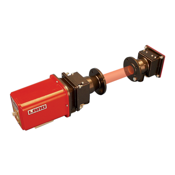
User Guide Model 4200 Dust & Opacity Monitor System Description 4.1 The System The Land Model 4200 Continuous Opacity/Dust Monitoring System normally requires only two major components to complete a monitoring system. The double pass instrument is known as a transmissometer. A transmissometer installed with a retro-reflector on the opposing side of the stack or duct operate as a double pass cross stack opacity/dust monitor. - Page 12 Model 4200 Dust & Opacity Monitor User Guide 4.1.1 Transmissometer The Land Model 4200 has been developed to be one of the most accurate and economical opacity/ dust monitors available. It uses a high-intensity LED source very low noise electronics and a sophisticated normalisation system to minimise calibration drift.
- Page 13 User Guide Model 4200 Dust & Opacity Monitor Transmissometer measurement mode (Shutters optional) Fig. 4-1 Transmissometer Unit Retroreflector Unit Fail-safe Shutter Unit Beamsplitter Detector (Measurement) Detector (Reference) Collomating Lens Span Calibration Filter Zero Point Reflector Reflector LED 1 LED 2 Mirror Page 7...
- Page 14 Model 4200 Dust & Opacity Monitor User Guide 4.1.2 Retro-reflector The retro-reflector is a small passive unit enclosing to IP65/NEMA4 specifications a removable reflector (especially easy to clean). The reflecting surface uses embedded corner cube technology. This technology is specifically designed to reflect the beam of light directly back along the line of transmission with a very large tolerance factor to whatever angle the light beam is received. A light restrictive aperture is factory selected to suit the path length required by the customer making it unnecessary for any further correction on site.
-
Page 15: Keypad Functions
User Guide Model 4200 Dust & Opacity Monitor 4.2 Keypad Functions The keypad located on the transmissometer display panel has four keys: Description of operation and display Mode When progressively pressed steps through: • Normal Opacity/Dust display • Calibration check •... -
Page 16: Display Panel Leds
Model 4200 Dust & Opacity Monitor User Guide 4.3 Display Panel LEDs When illuminated, indicates the presence of the 5 volt supply rail to the circuit boards. Alarm When illuminated, indicates a high Opacity/Dust alarm condition. System OK When illuminated, indicates no detected fault conditions and instrument is in normal operating mode ( not in calibration or alignment mode). -
Page 17: Installation
User Guide Model 4200 Dust & Opacity Monitor Installation 5.1 Preliminary Considerations The transmissometer should be mounted on the stack or duct in a position where it can detect a representative concentration of dust across the stack/ duct diameter. For new plant systems the transmissometer's location should be planned during the design stages;... - Page 18 Model 4200 Dust & Opacity Monitor User Guide Installation Site Requirements Model 4200 Fig. 5-2 Installation Dimensions for Instrument Key 1. Transmissometer Fail Safe Shutter 3 . Retro-Reflector 4 . Flange to flange pathlength Page 12...
- Page 19 User Guide Model 4200 Dust & Opacity Monitor IMPORTANT : Mounting Guidelines The Transmissometer (1) requires approximately 400mm (16in) with automatic fail safe shutters or 250mm (10in) without automatic fail safe shutters as a minimum distance beyond the stand pipes for installation (In addition adequate clearance for access is required for operation).
- Page 20 Model 4200 Dust & Opacity Monitor User Guide Fig 5-3 Standpipe Mounting Flange - Dimensions Fig. 5-4 Standpipe Mounting Flange Key 1. 3 Studs Shown on 100.0PCD Rubber Sealing Ring Spherical Washers M10 Nuts Disc Spring Washers Page 14...
-
Page 21: Standpipe Installation
User Guide Model 4200 Dust & Opacity Monitor 5.2 Standpipe Installation The Land Model 4200 is supplied with two mounting flanges with sleeves which are used to mount the transmissometer onto the stack/duct. The sleeves are 128 mm [5.24in] long (Fig 5-3/5-4). If necessary, shorten or lengthen the sleeves when mounting to obtain the proper measurement path. Unstable mounting bases such as thin sheet metal walls may require supplemental bracing (Figure 5-5). - Page 22 Model 4200 Dust & Opacity Monitor User Guide Cut a hole around the retro-reflector pilot hole, large enough to allow eventual welding of the OD of the flange stub to the stack wall. The mounting flange plate must be aligned parallel to the stack wall. Important The Land Model 4200 Opacity Monitor is factory set to the flange-to-flange measuring path as specified by the customer at the time of sale. During the welding and alignment procedures, be sure the flange-to-flange measurement path does not exceed ±1% of the distance specified. If the measuring path is easily accessible and short enough, the flanges can be aligned with an alignment tube (Fig 5-6). First slide the alignment tube through both flanges. Then, ensure the specified flange-to-flange measuring path is maintained to within ±1%, and tack weld the retro reflector flange in place. Make the necessary adjustments and weld the transmissometer flange in place.
-
Page 23: Alignment Tool
User Guide Model 4200 Dust & Opacity Monitor 5.3 Alignment Tool When the measurement length is too long to use an alignment pipe, Land Instruments International can supply a flange alignment tool to aid in aligning the flanges. Contact Land Instruments International if this part is required. The flange alignment tool consists of two plates which are mounted to the flanges (Fig. 5-7a). One plate supports a light source and the other plate supports optics with a target in the centre. When the flanges are properly aligned the light spot must be located in the centre of this target (Fig. - Page 24 Model 4200 Dust & Opacity Monitor User Guide Fig. 5-7a Fig. 5-7b Page 18...
-
Page 25: Air Purging
User Guide Model 4200 Dust & Opacity Monitor Air Purging 6.1 The Need for Air Purging It is important to supply air to the integral air purge units to ensure the optical system remains clean during operation. Standard Air Purge Unit Fail Safe Shutter Air Purge Unit Part Number 703-003 Part Number 703-073... -
Page 26: Electrical Installation
Model 4200 Dust & Opacity Monitor User Guide Electrical Installation Caution ALWAYS TURN OFF POWER BEFORE PERFORMING ANY ELECTRICAL WORK. 7.1 Cable Considerations The following cable considerations are the responsibility of the customer. Power supply and wiring to the fan/blower units - Fan motor ratings: 230V 50Hz... - Page 27 User Guide Model 4200 Dust & Opacity Monitor 7.2.1 Flexible Conduit Size The sockets also have a PG9 thread suitable for connecting directly to flexible conduit. PG (Panzerroht Gewind) is a European conduit thread size used extensively throughout the continent for electrical applications. Signal Cable Socket/Plug Terminations Plug pin number Description Normal Terminal State System OK Relay Open System OK Relay...
-
Page 28: Alignment
Model 4200 Dust & Opacity Monitor User Guide Alignment 8.1 Preliminary Alignment Correct installation and accurate alignment are essential if the Land Model 4200 is to function properly and meet its design specification. Important Ensure the air purge units, fans/airmovers are functioning and providing purge air to the transmissometer and retro-reflector units before installation begins. To mount the transmissometer and retro-reflector heads, it is necessary to remove the three M10 nuts (315.044) and spherical washers (703.022) from the mounting studs, leaving the stack of disc springs (318.327) in place. -
Page 29: Final Alignment
User Guide Model 4200 Dust & Opacity Monitor 8.2 Final Alignment Warning Eye and face protection must be worn when looking into hot gases. 8.2.1 Retro-reflector Alignment The instruments should be mounted and roughly aligned by the methods previously described. Adjustment nuts must not be over tightened. The fan/blowers and system air purges should be fully operational. - Page 30 Model 4200 Dust & Opacity Monitor User Guide 8.2.2 Transmissometer When the retro-reflector has been correctly aligned, the transmissometer should be aligned in a similar fashion, though in this case the alignment target is permanently visible in the sight aperture and it is simply necessary to centre the reflected flashing spot on the target by adjusting nuts X and Y on the transmissometer unit.
-
Page 31: Configuration
User Guide Model 4200 Dust & Opacity Monitor Configuration Several parameters are user configurable and must be set prior to commissioning the Model 4200. They are all accessible through the keypad and viewed on the LED display. 9.1 Display Modes The leading digit on the display indicates the present mode, except for SET OUTPUT. -
Page 32: Display Descriptions
Model 4200 Dust & Opacity Monitor User Guide 9.3 Display Descriptions Step through the selections by pressing the Mode key OPACITY/DUST display Normally this will display the opacity value in % or dust concentrations in mg/m dependent on which has been selected. Opacity readings will be in the range of 00.0% to 100%. Dust readings will range from 0 to 999mg/m Note... - Page 33 User Guide Model 4200 Dust & Opacity Monitor Full Display Flowchart Fig. 9-1 Page 27...
-
Page 34: Calibration
Model 4200 Dust & Opacity Monitor User Guide 10 Calibration 10.1 Calibration Audit To perform a calibration audit remove the front detail plate (Fig. 10-1) from the transmissometer to expose the display/ keypad unit. The display may be blank as a time out facility operates in the software. Press the Mode key (left key on keypad) until 'c' is displayed on the left hand side of display. -
Page 35: Linearity Filters
User Guide Model 4200 Dust & Opacity Monitor 10.1.2 Span Check Remove the reflector holder and turn it into the reverse plane so that when placed in the same filter holder position (1) as before. The blank, non reflective surface is now facing towards the display end of the instrument. After a short period of time the display value should read 100. This represents 100% opacity any deviation from this value signifies the span drift. - Page 36 Model 4200 Dust & Opacity Monitor User Guide Ensure that the instrument is correctly aligned and the optical path is clear. Remove the top cover plate on the transmissometer. The display must be blank (normally the software operates a time out facility after 10 minutes).
-
Page 37: Method 2 - Alternative Re-Calibration (Opacity)
User Guide Model 4200 Dust & Opacity Monitor 10.4 Method 2 - Alternative Re-calibration (Opacity) Re-calibration of the system may be carried out using this method with the units still in position on the stack, without clear stack conditions. Note This method does not calibrate out any changes with the retro-reflector. - Page 38 Model 4200 Dust & Opacity Monitor User Guide 10.5.1 Preparation The unit should be fully aligned and operational. Certain parameters as follows should be set in preparation. Select the Dust range by pressing the Mode key until the words 'OPAC' or 'duSt' is displayed.
- Page 39 User Guide Model 4200 Dust & Opacity Monitor e.g. Worked example - For a particular process four isokinetic samples were taken. Sample number Dust Value mg.m Isokinetic Dust Measured by 4200 Measurement Fig. 10-3 Dust Gradient (sample from graph, shown with dotted lines): 150/125 = 1.20 Dust Gain Factor = Gradient * 0.1 = 1.20 * 0.1 = 0.120...
-
Page 40: Maintenance
Model 4200 Dust & Opacity Monitor User Guide 11 Maintenance 11.1 Periodic Maintenance Routines The Land Instruments International Model 4200 has been designed for a minimal amount of routine maintenance in normal applications. To ensure a maximum monitor lifetime, however, the following maintenance schedule has been developed. -
Page 41: Cleaning The Optical Surfaces
User Guide Model 4200 Dust & Opacity Monitor 11.2 Cleaning the Optical Surfaces After prolonged use, it is likely that some contamination will occur on the optical surfaces of the Model 4200. The time taken for significant contamination to occur depends very much on the nature of the installation. but in a typical situation it should be sufficient to clean the optics every 90 days. Two optical components should be cleaned, using the lens cloth supplied by Land Instruments International. -
Page 42: Recommended Spares
Model 4200 Dust & Opacity Monitor User Guide 11.3 Recommended Spares Quantity Description Part Nº Comments Lens cloth 320.804 Air Filter Element 701.980 Replacement element for air blower unit Reflector Element Refer to Replacement reflector for retro-reflector table in Section 11.5 below 38mm ID Hose 306.046 Hose for failsafe shutters/fan/blowers Hose clips (Terry) 318.068 Securing clips for above hose... -
Page 43: Troubleshooting
User Guide Model 4200 Dust & Opacity Monitor 12 Troubleshooting 12.1 Error Codes Only a limited number of possible errors can be detected by the microprocessor system in the transmissometer and they are displayed as an error code. e.g. ER 15 This signifies a serious malfunction of the system. Contact Land Instruments International for advice and service. -
Page 44: First Line Servicing
Model 4200 Dust & Opacity Monitor User Guide 12.3 First Line Servicing In the event of a failure with the system, the customer should make some provisional checks and actions before calling Land Instruments International Service department. Always leave the fan/blowers operating while the transmissometer is in position on the stack. -
Page 45: Specification
User Guide Model 4200 Dust & Opacity Monitor 13 Specification 13.1 4200 Dust & Opacity Monitor System Performance Operating Principle: Cross-stack Transmissometer Operating Wavelength: 623 ±20nm Light Source: High Intensity LED (lifetime > 5 years) Accuracy: ±2% Opacity (Based on single pass opacity with 95% confidence coefficient) Repeatability: ±2% (±5% for pathlengh > 7.5m/25ft) Resolution: ±0.25% Drift:... - Page 46 Model 4200 Dust & Opacity Monitor User Guide Inputs/Outputs Current Loop Outputs: 0, 2, 4 to 20mA Relays: 1. System OK 2. Zero Cal in progress 3. Span Cal in progress 4. High level alarm (1) 5. High level alarm (2) 6.
- Page 47 Gas Monitoring Products Standard Terms of Warranty Land Instruments International warrant all products of our own manufacture to be within specified limits of calibration, if any, when despatched from our works. Also that they are free from defects in material and workmanship for normal use and service when used for their intended purpose within the limits of our specification.
Need help?
Do you have a question about the Land 4200 and is the answer not in the manual?
Questions and answers