Table of Contents

Subscribe to Our Youtube Channel
Related Manuals for Ametek CHATILLON DFIS Series


Summary of Contents for Ametek CHATILLON DFIS Series
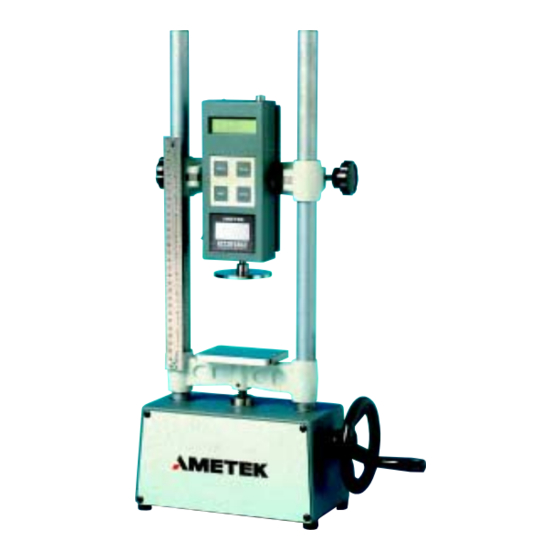
- Page 1 Instruction Manual NC001562 May 2001 Issue 3 ® CHATILLON DFIS Series ® ACCUFORCE AF2 Series Digital Force Gauges Operating Instructions CHATILLON DFIS Series Digital Force Gauge AMETEK AF2 Series Shown with MHTC Mechanical Test Stand - 1 -...
-
Page 2: Table Of Contents
TABLE OF CONTENTS Page INSTRUMENT PRECAUTIONS ....................1.0 INTRODUCTION AND PRODUCT OVERVIEW ............1.1 PRODUCT FEATURES ....................1.2 ELECTRICAL SAFETY ....................1.3 RECHARGING BATTERIES ................... 1.4 PHYSICAL DIMENSIONS ....................1.5 REVERSIBLE HOUSING ....................1.6 ABOUT THE KEYPAD ..................... 1.7 ABOUT THE DISPLAY ..................... 1.8 CONNECTION TO EXTERNAL DEVICES .............. - Page 3 This instrument is warranted against defects in workmanship, material and design for one (1) year from the date of delivery to the extent that AMETEK will, at its sole option, repair or replace the instrument or any part thereof which is defective provided, however, that the warranty shall not apply to instruments subjected to tampering or abuse, or exposed to highly corrosive conditions.
- Page 4 PRECAUTIONS Read the instruction manual completely before attempting to use the DFIS or ACCUFORCE 2 (AF2) Series. By following the instructions contained in this manual, the optimum accuracy and performance can be attained. IMPORTANT NOTE: The DFIS and ACCUFORCE 2 (AF2) gauges are identical in function- ality.
-
Page 5: Introduction And Product Overview
INTRODUCTION AND PRODUCT OVERVIEW The DFIS/AF2 Series family of digital force gauges manufactured by AMETEK Test and Calibration Instruments Division. They have been designed to provide accurate compression and tension force measurements via an internal load cell. These instruments have been precisely crafted to provide years of reliable service. -
Page 6: Physical Dimensions
PHYSICAL DIMENSIONS REVERSIBLE HOUSING The DFIS/AF2 Series is shipped shaft-down for stand-mounted applications, and the display on the front of the gauge is configured accordingly. For performing operations in which the gauge will be hand-held, it may be desirable to rotate the front of the casing so that the display and logo will be shown right side up. To do so, remove the two screws from the back of the casing, carefully rotate the front of the casing 180 degrees being careful not to pull, pinch, or twist the wires inside, and then reinstall the screws. -
Page 7: About The Keypad
ABOUT THE KEYPAD The keypad consists of four dedicated keys (PEAK, UNITS, ZERO, XMIT). The keypad is operational when the power switch, located on the side of the gauge, is in the ON position. PEAK key cycles through three different operating modes: capture of the Normal reading;... -
Page 8: Connection To External Devices
I/O Connector (View from Solder End) The DFIS/AF2 Series is supplied with a 12-pin female connector to provide both digital and analog outputs. AMETEK offers a variety of cables to handle most applications (Refer to Section 1.9). Select the cable type required to connect the gauge to the peripheral device using the mating connector. -
Page 9: Interface Cables
INTERFACE CABLES Cable Description NC000652 6 ft (182 cm), Connects to a personal computer with a 25-pin RS-232 connection. NC000652-1 10 ft (305 cm), Connects gauge to a personal computer with a 25-pin RS-232 connection. NC000652-2 15 ft (450 cm), Connectsto a personal computer with a 25-pin RS-232 connection. -
Page 10: Setting Up For Safe Use
1.10 SETTING UP FOR SAFE USE The DFIS/AF2 Series should be properly setup before accurate and most of all, safe measurements can be made. Only when you have verified that you will be conducting a safe test, proceed as follows: Determine what and how it will be tested and verify that the DFIS/AF2 Series can handle the test. -
Page 11: Front Panel Operation
FRONT PANEL OPERATION The DFIS/AF2 Series can operate in one of the three modes: Normal, Data Collect and Configuration. NORMAL MODE The principal function of the Normal mode is to provide indications of load applied to the load cell. Instantaneous force, peak-tension and peak-compression readings can be displayed and scaled in a variety of units of measure. -
Page 12: Zeroing
2.1.3 Zeroing Zeroing allows you to exclude the weight of accessories and attachments from the indicated force readings. It also clears captured peak tension and compression readings. To zero the gauge, momentarily press the ZERO key. Only the current measurement type (i.e., NORM, T-PK, C-PK) will be zeroed. To zero and clear all measurement types press and hold the PEAK key and then press the ZERO key. -
Page 13: Configuration Mode
CONFIGURATION MODE The Configuration Mode facilitates the communications setup for the gauge. 2.2.1 Configuring Output Port- Analog Output The analog output is always available at the output port without configuration. The analog output is 0 to -1.50Vdc (min) in tension mode and 0 to 1.50Vdc (min) in compression mode. 2.2.2 Configuring Output Port- Digital Output The DFIS/AF2 gauge supports three types of digital output: Modified BCD (Mitutoyo), RS232 Numerical Data Only and RS232 Full Data. -
Page 14: Enabling The Mitutoyo Output
2.2.2.1 Enabling MITUTOYO Digital Output To enable the MITUTOYO digital output, turn the gauge power OFF. UNITS 0 0 0 H XMIT - NOTICE - You must power down the gauge to configure the digital output and communication specifications for the gauge. To enable the MITUTOYO output, with gauge power OFF, DEPRESS and HOLD the... -
Page 15: Enabling The Rs-232 Port- Numerical Data Only
2.2.2.2 Enabling RS232 Digital Output- Numerical Data Only To enable the RS232 digital output with numerical data only, turn the gauge power OFF. UNITS XMIT - NOTICE - You must power down the gauge to configure the digital output and communication specifications for the gauge. -
Page 16: Enabling The Rs-232 Port- Full Data
2.2.2.3 Enabling RS232 Digital Output- Full Data (Default) To enable the RS232 digital output with full data, turn the gauge power OFF. Full data means that UNITS will be included with your force value during transmission to an external device. UNITS XMIT - NOTICE -... -
Page 17: Modifying Communication Parameters
2.2.2.4 Modifying Communication Parameters You may change the communication parameters for the force gauge by sequencing through the communi- cation setup display. UNITS 9 6 0 0 XMIT - NOTICE - You must power down the gauge to configure the digital output and communication specifications for the gauge. -
Page 18: Data Collect Mode
DATA COLLECT MODE The DFIS/AF2Series can accept and execute commands through the RS-232 serial port. The command set is tailored to make it easy to configure and operate the instrument under computer control. 2.3.1 About Data Collect Mode Data transmitted by the gauge in Data Collect mode is a filtered average of 45 instantaneous force readings. Digital filtering is employed to eliminate false readings resulting from noise and vibration. - Page 19 The DFIS/AF2Series can accept and execute commands through the RS-232 serial port. The command set is tailored to make it easy to configure and operate the instrument under computer control. The string commands are sent as ASCII characters. The following string commands are recognized: Command Response Description...
- Page 20 CALIBRATING THE DFIS/AF2 SERIES The DFIS/AF2 Series may be field calibrated, however, for optimum performance, it is recommended that your gauge be factory calibrated at least every other year or more frequently depending on your frequency of use. Field calibration is recommended every 6 to 12 months. A 5-point calibration is required where five different calibrated weights are applied to the load shaft at increments of 20%, 40%, 60%, 80% and 100% of capacity.
Need help?
Do you have a question about the CHATILLON DFIS Series and is the answer not in the manual?
Questions and answers