Table of Contents

Related Manuals for Ametek Surtronic 25


Summary of Contents for Ametek Surtronic 25
- Page 1 Surtronic 25 User’s Guide K505/125-01 Issue 4 Taylor Hobson Ltd PO Box 36, 2 New Star Road, Thurmaston, Leicester LE4 9JQ, England Telephone +44 (0)116 2763 771, Fax +44(0)116 274 1350 E-mail: taylor-hobson.uk@ametek.com www.taylor-hobson.com...
-
Page 3: Table Of Contents
Surtronic S25 Chapter 1 Introduction to Surface Texture terminology and definitions ......1-1 Surface Texture Definitions ...... 1-1 Parameter Definitions ....... 1-3 Ra ............1-3 Rp ............1-3 RSm ............. 1-3 Rz ............1-3 Rz1max ..........1-3 Rt ............1-4 Rmr ............1-4 RPc ............ - Page 4 Making a measurement ......3-2 Switching the Surtronic 25 ON ... 3-2 To cancel a measurement ....3-4 Using the Surtronic 25 with a PC ..... 3-4 Printing ............3-4 To cancel print: ........3-5 Chapter 4 Menu Settings ..4-1 Main Menu ..........
- Page 5 Range Selector Table ......4-4 Print Settings: ........4-4 Units: ............ 4-4 Filter: ............ 4-4 Dump Mode: ......... 4-5 Dump Mode (Using your Surtronic 25 with a PC) ........... 4-5 SPC Mode ........... 4-5 Language Settings ........4-6 Chapter 5 Making Measurements - Technical Considerations ..5-1...
- Page 6 Surtronic S25 Specification for Data Dump ..... 5-8 Chapter 6 Accessories ..... 6-1 Alternative standard pick-up (112/1503) .. 6-1 Small bore pick-up, 5mm (200min) stylus tip radius (112/1504) ........6-1 Small Bore Pick-up (112/2673) ....6-1 Narrow Gauge Stylus (155/P11610) ..6-2 Right Angle Pick-up, 5mm (200min) stylus tip radius (112/1505) ........
- Page 7 Surtronic S25 Portable Printer 112/3469-01 ....6-8 Replica Kit (112/727) ........6-9 Portable base (137/1734) ......6-10 Chapter 7 Maintenance .....7-1 Calibration ..........7-1 Reference Standard ......7-1 Sensitivity Check and Adjustment ..7-1 Pick-up with Chisel Edge Stylus ..7-2 Cleaning the Stylus ........
- Page 8 Surtronic S25 Page vi...
-
Page 9: Chapter 1 Introduction To Surface Texture Terminology And Definitions
Surtronic S25 Chapter 1 Introduction to Surface Texture terminology and definitions Surface Texture Definitions Every components surface has some form of texture which varies according to its structure and the way it has been manufactured. These surfaces can be broken down into three main categories: Surface roughness, Waviness and Form. -
Page 10: Parameter Definitions
'Exploring Surface Texture', published by Taylor Hobson. Parameter Definitions Surface texture is quantified by parameters which relate to certain characteristics of the texture. The Surtronic 25 offers the following parameters: Page 1-2... -
Page 11: Rsm
Surtronic S25 Ra, Rp, Rsm, Rz, Rt, Rmr, RPc, Rz1max, Rsk, Rda Additional parameters can be analysed by downloading results to optional software. Ra. Ra is the universally recognised, and most used, international parameter of roughness. It is the arithmetic mean of the absolute departures of the roughness profile from the mean line. -
Page 12: Rmr
Surtronic S25 Rt. Total Height of the Profile. Rt is the Maximum Peak to Valley Height of the Profile in the Assessment (evaluation) Length (ln). Rmr. Material Ratio is the length of bearing surface (expressed as a percentage of the evaluation length ln) at a depth below the highest peak. - Page 13 Surtronic S25 Further details are included in the Taylor Hobson booklet 'A Guide to Surface Texture Parameters'. Page 1-5...
- Page 14 Surtronic S25 Page 1-6...
-
Page 15: Chapter 2 Description
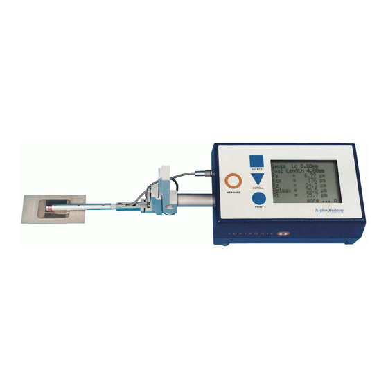
Surtronic S25 Chapter 2 Description The Surtronic 25 is a portable, self-contained instrument for the measurement of surface texture and is suitable for use in both the workshop and laboratory. Parameters available for surface texture evaluation are: • Ra, Rz, Rt, Rp, Rmr, RPc, Rv, Rz1max, Rsk, Rda... -
Page 16: The Equipment
Surtronic S25 The Equipment The standard Surtronic 25 M112/3522-01 includes: • 1off Traverse unit: 112/3522-01 • 1 off Standard Pickup: 112/1502 • 1 off Reference Specimen: 112/1534 • 1 off Pickup cable: 112/1257 • 1 off Screwdriver: QA 0001 •... - Page 17 Surtronic S25 The unit also contains a drive motor which traverses the pickup across the surface to be measured. The measuring stroke always starts from the extreme outward position. At the end of the measurement the pickup returns to this position ready for the next measurement.
-
Page 18: Pick-Up Mounting Components
Surtronic S25 Pick-up Mounting Components The pick-up is fastened to the drive shaft by the following means: Mounting Bracket. This is clamped to the drive shaft by means of a knurled knob. Although normally used upright, as shown in figure 3, it can be turned to angle the pick-up or to take it off the centre line, as shown in figure 3a. - Page 19 Surtronic S25 Figure 3a Figure 3b Adjustable Support. This can be clamped at any position on the slide of the mounting bracket to provide pick-up height adjustment. Pick-up holder. This fits into the crutch of the pick-up support and is held in place by a spring plunger. A biased holder, when used as shown in figure 3, exerts a biasing force on the pick-up (depending on which way the holder is inserted into the support crutch).
- Page 20 Surtronic S25 Figure 4 The holder will hold the pick-up at right angles to the drive shaft when it is pivoted away from the surface (eg while changing the work piece). Connector. The connector of the pick-up lead is screwed into the end of the pick-up and is then inserted into the end of the pick-up holder, with the lead coming out through the slot in the holder.
- Page 21 Surtronic S25 movements of the stylus relative to the skid are detected and converted into a proportional electrical signal. The radius of curvature of the skid is much greater than the roughness spacing. This enables it to ride across the surface almost unaffected by the roughness, and provide a datum representing the general form of the surface.
- Page 22 Surtronic S25 There are several different types of pickup available designed for different applications, details are given in the Accessories section of this handbook. They differ only in the stylus tip radius, the dimensions of the housing or position and the shape of the skid. The stylus material in all the pickups is diamond for low wear.
-
Page 23: Mounting
Surtronic S25 Mounting On a flat surface the display-traverse unit can be supported on its three feet. If the unit is to be used on a roll or in a large bore, unscrew the three feet and use them to fasten an optional roll and bore plate to the bottom of the unit;... - Page 24 Surtronic S25 Page 2-10...
-
Page 25: Chapter 3 Getting Started
Surtronic S25 Chapter 3 Getting Started Battery To insert a battery, open the compartment by sliding the door to the right and remove the door from the unit. Insert the battery, with the terminals positioned as shown in the diagram on the floor of the battery compartment. -
Page 26: Making A Measurement
(see Chapter 7). Note 2: Successful use of the Surtronic 25 will only be possible if it is operated on a surface free from external vibration - see also operating notes in Chapter 5. - Page 27 Surtronic S25 The default settings are: Parameter : Ra Cut-off : 0.8mm Evaluation length : 4.0mm Range : 100µm Data dump evaluation length : 4.0mm Data dump range : 100µm No parameter/graph selected for printout Language English Filter Gaussian If the user wishes to change any of these settings, this can be car- ried out using the Scroll and Select keys (see Chapter 4 for...
-
Page 28: To Cancel A Measurement
Measurement Cancelled is displayed. Using the Surtronic 25 with a PC If the Surtronic 25 is connected to a PC then measurements will be taken in dump mode, which is selected using the Scroll and Select keys from the main menu (see next chapter for full set-up details). -
Page 29: To Cancel Print
Surtronic S25 To cancel print: Pressing the PRINT key during printout (before display has updated to Main menu state) stops the printout and "Printer cancelled" is displayed for 2 seconds. The normal update to Main-state then continues. Page 3-5... - Page 30 Surtronic S25 Page 3-6...
-
Page 31: Chapter 4 Menu Settings
Surtronic S25 Chapter 4 Menu Settings The operation of the Surtronic 25 is based on making selections from menus presented on the liquid crystal display. Two menu states exist, these are: Main Menu and Data Dump Menu. The Data Dump menu is accessed via the Main Menu and is used when connecting to a PC. - Page 32 Surtronic S25 toggle through the evaluation length options until the required length is highlighted on the screen, then press the Select key. The evaluation length options are determined by the cut-off length selected. Parameters: select the Parameters option from the main menu. A list of the parameters available will appear on the screen (see below).
- Page 33 Surtronic S25 The SCROLL key will cycle through 'Mr% + Offset', 'Mean line + Offset' and 'Exit'. The SELECT key will allow the alteration of one of the 2 settings or, if Exit is highlighted, will return to the main parameter selection screen. Pressing SCROLL will step the cursor (or highlighted character) through the 3 decimal digits of the percentage, then the...
-
Page 34: Range Selector Table
Surtronic S25 Range: Allows the user to scroll through the range options. For optimum performance it is advised to recalibrate after changing range. The most common settings are as follows: For surfaces <10 micron peak to valley- select range of 10µm For surfaces <100 micronpeak to valley- select range of 100µm For surfaces <300 micron peak to valley- select range of 300µm Range Selector Table... -
Page 35: Units
Surtronic 25 to a PC (see below) Dump Mode (Using your Surtronic 25 with a PC) If using the Surtronic 25 with a PC you will need to select the DUMP MODE option from the main menu. Scroll to Dump mode ON. -
Page 36: Language Settings
OK selected the previous screen will be shown again. ModeON Language Settings The default on the Surtronic 25 is English Language. If the user wishes to select other languages, press the PRINT SCROLL buttons down simultaneously. The following... - Page 37 Surtronic S25 Selecting OK displays the Select language and select SPC mode screen Select Language Select SPCmode Quit Scroll down the options with and click to select Select Language English Français Deutsch Italiano Scroll down the list of languages with and click to select This selection will remain as the default unless power is lost (eg battery is removed).
- Page 38 Surtronic S25 Page 4-8...
-
Page 39: Chapter 5 Making Measurements - Technical Considerations
Surtronic S25 Chapter 5 Making Measurements - Technical Considerations Operating Notes Before measurements are made, there are a few general points of procedure which should be observed. The surface to be measured must be free from vibration and the instrument must be completely steady during a measurement. -
Page 40: On Other Surfaces
Surtronic S25 Make the cut-off/length and parameter selections required Position the display-traverse unit and pick-up so that the stylus contacts the surface and the pick-up is approximately parallel to the surface. Make sure that the length of surface is sufficient for measurement, remembering that the traverse motion is inwards towards the display-traverse unit. -
Page 41: Evaluation Length
Surtronic S25 Evaluation Length A long evaluation length is mainly for use on sheet metal and similar materials, where a longer surface is required to be representatives of the material being examined. Table of Cut-off values If not otherwise indicated on a drawing, the following should be used to determine the cut-off λc (ISO4288)-1996. -
Page 42: Operating Error Indications
Surtronic S25 Operating Error Indications During a measurement a message may be displayed which indicates that an error condition has occurred. The messages and the probable causes for their display are as follows: Display Reason for message Motor Error Motor fault Pick-up Error Response at pick-up level error or faulty connection Over range... - Page 43 Surtronic S25 Measure pressing PRINT key before measurement before print No parameter pressing PRINT key before selecting selected printout parameters Printer not pressing PRINT key when printer not connected connected or no computer connected to receive dump data. Printing pressing PRINT key during data transmission to cancelled printer (stop printing).
-
Page 44: Specification
Surtronic S25 Specification Battery Alkaline: minimum 600 measurements of 4mm measurement length Ni-Cad: minimum 200 measurements of 4mm measurement length Size: 6 LR 61 (USA/Japan), 6 F 22 (IEC) Fixed battery / external charger External charger (Ni-cad only): 110/240V, THP No 112/1591 50/60Hz Traverse Speed:1mm/sec Measurement: metric/inch units... -
Page 45: Rs232 Output
Surtronic S25 Calculation time:Less than reversal time or 2 sec whichever is the longer Accessory : 9 pin D-connector female. Containing: socket RS232 hardwired handshake (RS232 level). Transmit function only hardware implemented. Remote start (5V logic) Remote start: short to ground Constant power on instrument (5V logic) When connected to Ground, constant power is on. -
Page 46: Specification For Data Dump
Cutoff = xxx mm Evaluation length = xxx mm Filter = xxx Specification for Data Dump The following format is used for data dump from Surtronic 25 to a Transmission set up is as follows: Baud rate: 9600 Baud Number of data bits: 8... - Page 47 Surtronic S25 Transmission: RS232 Transmitted data is unfiltered No parameters are calculated. Transmission data: Data type Function Comments 2 bytes Number of data values Total number of transmitted data values 1 byte Ordinate spacing Number of data values per mm 1 byte First data value Resolution 10nm...
- Page 48 Surtronic S25 Page 5-10...
-
Page 49: Chapter 6 Accessories
Surtronic S25 Chapter 6 Accessories Alternative standard pick-up (112/1503) Details as the standard pick-up, see figure 6, page 2-8, but with 10mm (400min) stylus tip radius. Conforms to US specifications (ANSI B46.1). Small bore pick-up, 5µm (200µin) stylus tip radius (112/1504) For general use in small bores, on narrow surfaces and in grooves, or with the skid supported independently of the surface being measured. -
Page 50: Narrow Gauge Stylus (155/P11610)
Surtronic S25 Narrow Gauge Stylus (155/P11610) For measuring in 'O' rings and narrow grooves up to a depth of 5.5mm (0.22in). Right Angle Pick-up, 5µm (200µin) stylus tip radius (112/1505) This pick-up is used at right angles to the direction of traverse. Accordingly the skid is set at right angles to its normal position. -
Page 51: Recess Pick-Up, 5Mm (200Min) Stylus Tip Radius (112/1506)
Surtronic S25 Figure 11 Conditions to be observed when the right angle pick-up is used on a cylindrical work-piece Recess pick-up, 5µm (200µin) stylus tip radius (112/1506) This pick-up has an extended stylus and skid for measuring at the bottom of a recess, or between shoulders and flanges up to 5.7mm deep. -
Page 52: Recess Pick-Up (112/2672)
Surtronic S25 Recess pick-up (112/2672) As above, but with 2µm (80µin) tip radius Chisel edge pick-up (112/1524) For measuring along a sharp edge or a wire which cannot be traversed with a normal stylus. The pick-up has a rotatable square skid. Not for use on flat surfaces. Figure 13: The chisel-edge pickup Figure 14: Use of the chisel edge pickup Page 6-4... -
Page 53: Side-Skid Pick-Up (112/1531)
Surtronic S25 Side-skid pick-up (112/1531) For use on curved surfaces such as gear teeth. The skid surrounds the stylus and the line of contact with the component moves relative to the stylus as it traverses over the crest of the curve. Figure 15: The side skid pickup It is very important to position this pick-up so that contact with the surface is made on the centre line (parallel to the axis of the... -
Page 54: Detachable Skid (112/1191)
Surtronic S25 Figure 16: shoe pickup This pick-up should never be used on a smooth surface because the shoe would tend to wring to the surface. Ideally the pick-up should be parallel to the surface being measured, but in any case, the inclination must not exceed +/- 10°... -
Page 55: Extension Rod (112/1533)
Surtronic S25 Figure 17: pick-up fitted with detachable skid Extension rod (112/1533) 100mm long extension with integral lead, fits between the pick-up and carriage. The extension rod is fitted to the pick-up in the following manner: 1. Disconnect the pick-up lead from the traverse unit and remove the pick-up from the traverse unit carriage. -
Page 56: Portable Printer 112/3469-01
112/3469-01 The connector is a 9 way D type socket. The interfacing cable for the printer to Surtronic 25 is 112/2471 and is included as standard with the printer. Cable connections shown below are for technical reference only. -
Page 57: Replica Kit (112/727)
Ra value. Portable base (137/1734) The Surtronic 25 can be mounted on a portable base for use in measuring large components in situ. The base is fitted with 3 feet which can be positioned at a number of places on the base, enabling it to be steadied on a variety of components. - Page 58 Surtronic S25 Page 6-10...
-
Page 59: Chapter 7 Maintenance
Surtronic S25 Chapter 7 Maintenance Calibration Reference Standard The sensitivity of the instrument is checked with the reference specimen supplied. This comprises a ruled surface having an Ra value accurate to within 4% of the value marked on its mount. A UKAS calibration certificate can be supplied for this standard. -
Page 60: Cleaning The Stylus
Surtronic S25 is located in the front panel of the Display Unit, just above the pick-up connector. Repeat the measurement and adjustment, until the measured value is within 2% of the value marked on the specimen. Cleaning the Stylus Occasionally clean the stylus with a camel hair brush moistened with a proprietary cleaning agent.
Need help?
Do you have a question about the Surtronic 25 and is the answer not in the manual?
Questions and answers