Table of Contents
Advertisement
Quick Links
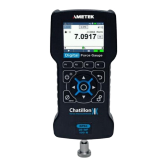
DF3 Series Digital Force Gauges
The Chatillon® DF3 Series is a family of digital force gauges ideal for handheld and test stand applications.
These battery powered gauges are used to measure axial tensile and compressive forces. The DF3 series is
available in several capacities, making them suitable for various basic and complex applications.
The following models represent the DF3 Series force gauges:
DFE3 Series
•
DFS3 Series
•
NOTE: The functions and features described in this user's guide may not be available on all DF3 models.
POWERING GAUGE ON/OFF The DF3 Series gauge has a dedicated power key. Depress the key for 2
seconds to turn the gauge ON or OFF.
Advertisement
Table of Contents

Related Manuals for Ametek Chatillon DF3 Series


Summary of Contents for Ametek Chatillon DF3 Series
-
Page 1: Df3 Series Digital Force Gauges
DF3 Series Digital Force Gauges The Chatillon® DF3 Series is a family of digital force gauges ideal for handheld and test stand applications. These battery powered gauges are used to measure axial tensile and compressive forces. The DF3 series is available in several capacities, making them suitable for various basic and complex applications. - Page 2 When the gauge is powered on, the Splash screen is displayed for approximately 5 seconds. This display shows AMETEK STC and Chatillon® logos along with Gauge Model, Firmware Version and the Last Calibration Date.
-
Page 3: Table Of Contents
Contents DF3 Series Digital Force Gauges ..................1 Introduction ......................... 6 Battery ..........................6 Battery Life ........................7 Charging: .......................... 7 Charge Time: 4 hours ....................7 Charging Temperature: ....................7 Battery Safety and Precautions ..................7 Failure to follow these safety precautions can result in damage to the battery which can cause fire or explosion ................ - Page 4 Compression Setpoint ....................20 Tension Setpoint ......................20 Status Bar ........................... 21 Screens ..........................22 Configuration Screen ......................22 Accounts Settings Option ....................22 Password Enable ......................22 Change Password ......................24 General Settings Option ....................25 Language ........................26 Key Tones ........................
- Page 5 Resolution ........................39 Load Resolution ......................39 Test Setup Results ......................40 Save ..........................40 Export ..........................41 Test Setup: Start/Stop ....................... 42 Stop Condition ....................... 42 Auto Zero ........................45 Home Screen ........................46 Information Screen......................46 Battery Information ......................47 Status ..........................
-
Page 6: Introduction
Test Statistics ........................56 Switch between Result Statistics ................... 56 Exporting Statistics ......................56 Plotting Graph ....................... 59 Tests ..........................59 Break Detection ......................... 59 Sharp Break ........................60 Percentage Break ......................60 Break Detection Setup ...................... 60 Enable/Select Mode ....................... 61 Method ........................... -
Page 7: Battery Life
Battery Life Run time: 25 hours (full LCD brightness, no use of remote modules) Note: Dimming the display will further extend the battery charge. • Use of remote modules will reduce battery charge. • Charging: Charge Time: 4 hours To charge the gauge, plug the USB cable into any suitable USB port or charger. Charging Temperature: The battery can only be charged in the temperature range of 10 to 45°C. -
Page 8: Display Layout
Display Layout The DF3 Series digital force gauge features a TFT-LCD full-color display with backlight. Display Options The DF3 Series gauge features the following display options designed to enhance operation and performance: Display Orientation • Display Backlight • Hide Measurements •... -
Page 9: Hide Measurements
Hide Measurements This function allows the user to “hide” the readings displayed on screen. The “hide” function is useful for blind study applications. This setting can be turned ON/OFF from the Test Setup: Display screen. NOTE: Higher Display Backlight reduces the battery life. Keypad Operation The DF3 Series gauge has nine (9) keys and a navigation pod. -
Page 10: Overview
Overview Load Bar Graph The Load Bar Graph gives the user a visual indication of the absolute load being applied to the gauge. The percentage of applied load with respect to the maximum load capacity of the gauge is also displayed at the centre of the load bar graph. -
Page 11: Numeric Keypad
When the applied load is greater than 90% of the maximum range, the load bar graph is Red in colour. Numeric Keypad When a setting requires the user to input a numeric value, for e.g. Preload value or Trigger point, numeric keypad is set up on the screen to accept an input from the user. - Page 12 Key features of the numeric keypad When the numeric keypad is set-up, the current value is displayed on screen. The user can edit the current • input by erasing the last value using the F4 key or overwrite the previous input by entering the new value The '.' button is enabled only when the selected setting accepts a floating point value and is disabled once a •...
-
Page 13: Pass/Fail Limits
To read on about button functionalities, please refer to the Gauge Buttons section. The table below shows the configuration settings that require a numeric input from the user - Pass/Fail Limits The DF3 Series force gauge allows the user to set separate Pass/Fail limits for each result in a test. For e.g. we can set separate limits for T-Peak and Load Averaging and the test status will depend on whether the T- Peak or the Load Average value lie within the corresponding limits. -
Page 14: Setpoint Method
Pass/Fail limits can be configured from the Test Setup: Results screen. This screen allows the user to select a particular result and configure the Pass/Fail limit as per requirement. The Pass/Fail limits can be disabled or set using either the Setpoint or the Bandwidth... -
Page 15: High Setpoint
High Setpoint The High Setpoint determines the upper Pass/Fail limit. If the final result exceeds this value, the result status is FAIL_HIGH. The user must make sure that the entered value is less than the maximum gauge capacity. Low Setpoint The Low Setpoint determines the lower Pass/Fail limit. - Page 16 ## Bandwidth Method comment: <> (Bandwidth Method) The Bandwidth method allows the user to set pass/fail limits with respect to a Nominal Value. Under this method, the user will set values for the Nominal value Bandwidth percentage using the numeric keypad.
-
Page 17: Nominal Value
Nominal Value The Nominal Value determines the midpoint around which the bandwidth is calculated. The user must make sure that the entered value is such that the limits are lower than the maximum gauge capacity. Bandwidth Percentage... -
Page 18: Saving Changes
The Bandwidth Percentage determines the percentage of Nominal value that'll be added to and subtracted from the Nominal value in order to set the high and low limits respectively. The user must make sure that the entered value is such that the limits are lower than the maximum gauge capacity. Saving Changes When changes are made to the configuration settings, the DF3 Series gauge gives the user an option to save the changes made. -
Page 19: Load Safety Limit Setup
The Load Safety Limit can be configured from the Test Setup: Configure screen. Load Safety Limit Setup To setup the Load Safety Limits function, the user must enable the Load Safety Limits from the Test Setup: Configure screen. The Load Safety Limit screen allows the user to configure the following settings: Enable •... -
Page 20: Compression Setpoint
Compression Setpoint The Compression Setpoint is the load value re-presenting the highest COMPRESSION load value that you want your gauge to measure prior to it giving a Load Limit indication. On the Test Setup: Initialize, You have the option of enabling or disabling the Safety Limits Buzzer. If ON, the Buzzer provides you with an audible indicator when the load measurement exceeds a Compression Setpoint. -
Page 21: Status Bar
Status Bar The Status Bar has the following icons: Battery Percentage • Battery Indicator • Charger Plugged • • Warning •... -
Page 22: Screens
Screens Configuration Screen Configuration screen allows the user to configure the device as per requirement. It navigates the user to screen that provide an option to customize the gauge based on the user's preferences. From the Home screen, press and hold the Settings key for 2 seconds to load the Configuration screen. - Page 23 To Enable/Disable password protection, navigate to the Accounts screen and select the Password 'Enable' option. The display will show the 'Enter PIN' screen. Using the navigation keys, position the cursor to each desired digit and press the Select key to enter and then navigate to the next one (a maximum of 4 digits is currently permitted).
-
Page 24: Change Password
NOTE : The factory default pin is "0000". Change Password The DF3 Series gauges give the users an option to set a 4-digit password to prevent any unauthorized changes to the Test Configurations. To change the Password, navigate to the Accounts screen and use the Navigation key to set cursor on Change Password. -
Page 25: General Settings Option
If the entered password is valid, the user will have to re-enter the new PIN to update the password. In case the passwords don't match, the gauge will throw an error message prompting the user. If the entered passwords are valid, the gauge will throw a 'PIN changed successfully' message and update the account password. -
Page 26: Language
The General screen can be used to set the following parameters – Language • Key Tones • Display • Brightness • Zero On Start • Auto Shutdown • Auto Dimming • Language The Language setting allows the user to change the gauge language. On the General screen, use the Navigation keys to set the cursor on the Language setting. -
Page 27: Key Tones
German • Spanish • Chinese • Key Tones The Key Tones setting allows the user to switch ON/OFF key press buzzer. On the General screen, use the Navigation keys to set the cursor on the Key Tones setting. To change the Key Tones state, press the Select key to toggle the between ON/OFF states. -
Page 28: Brightness
If the Orientation option is Normal, displayed information is presented right-side down. The Function keys map to the function tags. If the Orientation option is Inverted, displayed information is presented upside down. The Function and Navigation key functionalities are swapped. Brightness The Brightness setting allows the user to adjust the display backlight. -
Page 29: Auto Shutdown
On the General screen, use the Navigation keys to set the cursor on the Zero On Start setting. To change the Zero On Start setting, press the Select key to open a list with available options. The user will have to exit Configuration screen and save changes for the Zero On Start setting to change. -
Page 30: Auto Dimming
The user can set a value between 1 - 300 minutes as the Auto Shutdown timeout. Auto Dimming The Auto Dimming setting, when enabled, dims the display backlight to minimum after a set duration of inactivity. When enabled, the user can set the Auto Dimming Timeout, which determines the duration of inactivity after which the display backlight is dimmed. -
Page 31: Test Setup Screen
The user can set a value between 10 - 3600 seconds as the Auto Dimming timeout. Test Setup Screen The DF3 Series gauges allow the user to setup a testing environment suitable for numerous testing scenarios. The Test Setup screen provides an easy-to-use interface to customize the test parameters as per requirement. -
Page 32: Test Setup: Display
Test Setup: Configure screen can be used to set the following test parameters – Peak Detection • Load Averaging • Break Detection • Safety Limits • NOTE - Only results that have been enabled in the Test Setup: Configure screen will be available in the Test Setup: Results screen. -
Page 33: Hide Measurements
On the Test Setup: Display screen, use the Navigation keys to set the cursor on the Result setting. To change the result, press the Select key to open a list with available result. The user will have to exit Configuration screen and save changes for the Result setting to change. -
Page 34: Lock Home
Lock Home The Lock Home Setting will restrict the user from changes on the Home screen. This is useful in making sure that the current unit and result aren't changed while on the Home screen. On the Test Setup: Display screen, use the Navigation keys to set the cursor on the Lock Home setting. -
Page 35: Peak Filter
On the Test Setup: Filter screen, use the Navigation keys to set the cursor on the Reading Filter setting. To change the Reading Filter, press the Select key to open a list with available values. The user will have to exit Configuration screen and save changes for the Reading Filter setting to change. -
Page 36: Test Setup Initialize
Test Setup Initialize From the Home screen, press and hold the Settings key for 2 seconds to load the Configuration screen. Navigate to the Test Setup option and press the Select key to load the Test Setup screen. Use the Left/Right key to navigate to the Test Setup: Initialize screen. -
Page 37: Polarity
ozf (Ounces Force) • gf (Grams Force) • lbf (Pounds Force) • Kgf (Kilograms Force) • N (Newtons) • On the Test Setup: Initialize screen, use the Navigation key to set the cursor on the Units setting and press the Select key to open Force option. To change the Force Unit, set cursor on Force and press the Select key to open a list with available Force Units. -
Page 38: Tones
If the Polarity is T +ve / C -ve, Compression loads will be assigned a negative value and Tension loads will be assigned positive values. Tones The DF3 gauge provides an audible alarm whenever a Load Limit has been reached . On the Test Setup: Initialize screen, use the Navigation keys to set the cursor on the Tones setting. -
Page 39: Resolution
The DF3 Series allows the user to select one of the following readings as the Default Zero option: Reading • Extension • Results • • Resolution The Resolution setting allows the user to set decimal places in Force, Torque, and Extensions readings. The DF3 gague provides maximum resolution is 6 and minimum is 1. -
Page 40: Test Setup Results
NOTE - Available resolution options depend on the Gauge model and the current unit. The DFS Series supports an extra resolution point. Test Setup Results Test Setup: Results screen help the user configure result limits and save/export options. From the Home screen, press and hold the Settings key for 2 seconds to load the Configuration... -
Page 41: Export
Export The Export setting allows the user to send the Test Results through the COM Port after a Test ends. All the results that have been enabled in the Test Setup: Configure screen will be exported. The user can toggle the Export setting by clicking the Select key when the cursor is positioned on it. -
Page 42: Test Setup: Start/Stop
Test Setup: Start/Stop Test Setup: Start/Stop screen lets to user setup the test Start and Stop conditions. From the Home screen, press and hold the Settings key for 2 seconds to load the Configuration screen. Navigate to the Test Setup option and press the Select key to load the Test Setup screen. - Page 43 On the Test Setup: Start/Stop screen, use the Navigation keys to set the cursor on the Stop condition setting. To change the Stop condition, press the Select key to open a list with available stop conditions. The available stop conditions will depend on the results that have been enabled in Test Setup: Configure screen.
- Page 44 If the Stop condition is set to 'On Load', the user gets to set a load value, upon reaching which the test stops. The load value set by the user must be less than the maximum gauge capacity. Stop Condition 'After Averaging' is available only if Load Averaging is enabled in Test Setup: Configure screen.
-
Page 45: Auto Zero
Auto Zero The Auto Zero setting automatically zeroes the selected values when a test is started. Once this is set, the user won't have to manual zero the values before starting the test. Auto Zero can be disabled by selecting the 'None' option. -
Page 46: Home Screen
Home Screen Information Screen The Information screen gives the user the general information and current status of the gauge. From the Home screen, press the Settings key once to load the Information screen. -
Page 47: Battery Information
Information screen consists of 4 sub-screens. Each sub-screen focuses on a specific aspect of the gauge – Gauge • Overloads • Calibration • Battery • The user can use Left/Right navigation keys to switch between these sub-screens. Battery Information From the Home screen, press the Settings key once to load the Informations... -
Page 48: Status
Status The 'Status' parameter indicates the current battery status. The user can charge the gauge by plugging the USB cable into any suitable USB port or charger. The gauge will also charge when connected to a TCM test stand. State of Charge (SoC) The State of charge (SoC) parameter displays the current battery charge as a percentage. -
Page 49: Calibrated On
Calibrated On The Calibrated On parameter lets the user know the last Calibration date. Calibration Due On The Calibration Due On parameter tells the user the next date when the gauge needs to be re-calibrated. Zero Offset The Zero Offset parameter indicates the percentage by which the Normal reading differs from the absolute load applied to the gauge. -
Page 50: Model
Model Displays the Gauge Model Serial Number Displays the Gauge Serial No. Firmware Version Shows the current Firmware version Build Version Shows the current Build version Hardware Version Shows the current Hardware version Overload Info From the Home screen, press the Settings key once to load the Information screen. -
Page 51: Number Of Overloads
Time (Last Overload) • Load (Last Overload) • Number of Overloads The Number of Overloads parameter lets the user know the number of time the gauge has been overloaded. The DF3 Series gauges keep track of the last 25 overloads. Time (Last Overload) The Time (Last Overload) parameter tells the user the date and time of the last recorded overload. -
Page 52: Test Results
Test Results Saving Results The DF3 Series gauges give the user an option to select whether to save the test results automatically at the end of a test run or to save manually from Results screen. This setting can be configured by setting the Save parameter to Auto/Manual from the Test Setup : Results screen. - Page 53 The results get exported only when the gauge to connected to a Serial Terminal like Termite. When not connected, the gauge will throw a "Not connected !" pop-up on the display. When manual export is selected, the user must navigate to the Test Results screen and press the F3 button to save the results.
- Page 54 The gauge doesn't respond if there's an issue with communication. This could be because the gauge is being used by another application or the command sent is incorrect. Another reason could be a disparity in setting.
-
Page 55: Clearing Results
Clearing Results The user can clear the current or all results from the Results by pressing the F4 button. A pop-up shows up, letting the user decide whether to clear the current result or all results. If the Password is enabled from the Accounts, the user will have to enter the PIN before clearing the results. -
Page 56: Test Statistics
Test Statistics Switch between Result Statistics The F1 button can be pressed to get a list of available statistics and switch to the statistic to be viewed. The user can also switch between statistics using the Left/Right buttons. Exporting Statistics The DF3 Series gauges give the user an option to export the test statistics manually from Statistics screen. - Page 57 The Statistics get exported only when the gauge to connected to a Serial Terminal like Termite. When not connected, the gauge will throw a "Not connected !" pop-up on the display. The user can decide whether to export the current statistic or all statistics. Before the exporting the statistics, the user must make sure that communication has been established with the serial terminal.
- Page 58 The gauge doesn't respond if there's an issue with communication. This could be because the gauge is being used by another application or the command sent is incorrect. Another reason could be a disparity in setting.
-
Page 59: Plotting Graph
Plotting Graph The F4 button can be pressed by the user to get a plot for the current result. The DF3 Series gauge allows the user to plot upto 300 data points and also displays Max, Min and Mean plotlines. If limits are on for the result selected, the user will also be able to see the high and low limits set by the user. -
Page 60: Sharp Break
The DF3 Series gauge will report the following as part of a Break Detect test: Break Load • Peak Load (T-PK or C-PK) • The DF3 force gauge allows you to perform two different methods: Sharp Break • Percentage Break •... -
Page 61: Enable/Select Mode
Enable/Select Mode • Method • Trigger Point • Percentage Drop • Enable/Select Mode From the Test Setup: Config: Break Detection screen, use the navigation keys to set the cursor on the 'Break Detection' option. Press the select key to toggle between 3 options shown below. Break Detection is 'Disabled' or 'Enabled' automatically by selecting either 'T-Break' or 'C-Break'. -
Page 62: Method
Method On the Test Setup: Config: Break Detection screen, use the Navigation keys to set the cursor on the 'Method' option. To change the Break Detect method, press the Select key to toggle between 'Sharp Break' and 'Percentage Break'. The user will have to exit the Configuration screen and save changes for the break detection settings to be applied. -
Page 63: Percentage Drop
The user will have to exit the Configuration screen and save changes for the trigger point setting to be applied. Percentage Drop The 'Percentage Drop to' value defines the percentage of the stored peak load value that the live reading must reach, for the DF3 gauge to activate the break detection. -
Page 64: Force Based
Force Based This load averaging test allows you to set a pre-load limit value or load threshold. The Preload value represents the “Start” and “End” point for your averaging function. The gauge will begin to collect and average the measured values once the “Preload Value” has been reached. The gauge will continue to average until the measured load drops below the Preload value. -
Page 65: Load Averaging Setup
Load Averaging Setup To setup the Load Averaging function, the user must enable the Load Averaging from the Test Setup: Configure screen. The Load Averaging screen allows the user to configure following settings: Enable • Preload Value • Timeout • Enable On the Test Setup: Config: Load Averaging... -
Page 66: Timeout
The user will have to exit the Configuration screen and save changes for the Preload value setting to be applied. Timeout Once the Load Averaging function is active, the 'Timeout' defines the duration for which the applied load will be averaged. The Load Averaging function will stop if the Timeout duration is elapsed or the applied load drops below the Preload value. -
Page 67: Peak Detection
Peak Detection Peak Detection is used when you want to capture the maximum load applied to a loadcell sensor. To run a Peak Detection test, the user must enable Peak Detection from the Test Setup: Configure screen. The DF3 Series gauges also gives the user an option to use a % Threshold for a Peak Detection test. When the user enables 'Use Threshold', Peak Detection starts only when the applied load exceeds the % value set of the... -
Page 68: Peak Compression
Peak Compression When the gauge is in Peak Compression mode (C-PK), the gauge will display the maximum compression load that was measured by the loadcell sensor. In addition to that, the user will also be able to view the Peak Compression value as a sub-reading when the gauge is in Normal or Compression Break (C-Brk) Mode. -
Page 69: Use Threshold
The user will have to exit the Configuration screen and save changes for the Peak Detection settings to be applied. Use Threshold This setting allows the user to choose whether or not to use threshold for Peak Detection. On the Test Setup: Config: Peak Detection screen, use the Navigation keys to set the cursor on the 'Use Threshold' option. - Page 70 On the Test Setup: Config: Peak Detection screen, use the Navigation Keys to set the cursor on the 'Peak Threshold' option. Press the Select key to open the numeric keypad. Enter the required Peak Threshold value. The user will have to exit the Configuration screen and save changes for the Peak Threshold setting to be applied.
Need help?
Do you have a question about the Chatillon DF3 Series and is the answer not in the manual?
Questions and answers