Sign In
Upload
Download
Table of Contents
Contents
Add to my manuals
Delete from my manuals
Share
URL of this page:
HTML Link:
Bookmark this page
Add
Manual will be automatically added to "My Manuals"
Print this page
×
Bookmark added
×
Added to my manuals
Manuals
Brands
Keysight Manuals
Measuring Instruments
CX3300 Series
User manual
Keysight CX3300 Series User Manual
Device current waveform analyzer
Hide thumbs
1
2
3
4
5
6
7
8
Table Of Contents
9
10
11
12
13
14
15
16
17
18
19
20
21
22
23
24
25
26
27
28
29
30
31
32
33
34
35
36
37
38
39
40
41
42
43
44
45
46
47
48
49
50
51
52
53
54
55
56
57
58
59
60
61
62
63
64
65
66
67
68
69
70
71
72
73
74
75
76
77
78
79
80
81
82
83
84
85
86
87
88
89
90
91
92
93
94
95
96
97
98
99
100
101
102
103
104
105
106
107
108
109
110
111
112
page
of
112
Go
/
112
Contents
Table of Contents
Troubleshooting
Bookmarks
Table of Contents
Table of Contents
Inspection
Installation
Safety Considerations
Environmental Characteristics
Bench Installation
Connecting a Mouse, Keyboard, and LAN Cable
Connecting Power
Connecting the CX1100
Turning On/Off the CX3300
To Turn on the CX3300
To Turn off the CX3300
Verifying Basic Operation
If You Use the CX1101A/CX1102A/CX1103A
Required Accessories
Procedure
If You Use the CX1104A
Required Accessories
Procedure
If You Use the CX1105A
Required Accessories
Procedure
Changing Windows Environment
Changing Operating System Settings
Installing Application Programs
Maintenance
Cleaning
Diagnosis
To Perform Diagnosis
User Calibration
Calibration
Troubleshooting
Servicing
2 Using the CX3300
Scope Mode and Data Logger Mode
Front Panel Overview
Side Panel Overview
Rear Panel Overview
Power on Screen
Main Waveform
Tool Palette
Sidebar
Summary Bar
Menu Bar
Status Bar
Indicator Tray
Setting the Display and the Starting Condition
Starting and Stopping Waveform Acquisitions
Adjusting the Horizontal Scale and Timebase Position
Adjusting the Horizontal Scale
Adjusting the Horizontal Timebase Position
Magnifying a Part of the Waveform
Adjusting the Vertical Settings
Adjusting the Vertical Scale
Adjusting the Vertical Offset
Magnifying a Part of the Waveform
Setting up Triggers
Setting the CX3300 for an Edge Trigger
Making a Measurement and Using Useful Tools
Making a Measurement on a Waveform
Using Markers
Using Math Functions and Filters
Using Analysis Tools
Using Quick Actions
Controlling Digital Channels
Using Data Logger Mode
Waveform Recording
Waveform Playback
Limitations of Waveform Recording
External Storage Device
Waveform Trend Analyzer
Waveform Analytics
Extracting Waveform Segments
Tagging Waveform Segments
Performing Clustering
Performing Waveform Analytics by Waveform Recording
Performing Waveform Analytics by Retriggering
Using Waveform Analytics Tool Palette
To Playback the Segments of the Specific Cluster
To Change the Number of Clusters
To Perform Detail/Retag Clustering
Current Waveform Analytics Software
Simulation of Sensors
SCPI Control
Saving and Printing Data
Forcing a Default Setup
SSD Recovery
Using Online Help
Accessing the Online Help
Navigating the Online Help
3 Performing User Calibration
Using the CX1101A/CX1102A/CX1103A
Using the CX1206A Sensor Head
Using the CX1104A
Using the CX1105A
Using the CX1151A
4 Safety Information
Safety Summary
Safety Symbols
Product Stewardship
Precautionary Statement
Working in Comfort
About Repetitive Strain Injury
What Is RSI
What Causes RSI
What if I Experience Discomfort
Mice and Other Input Devices
Advertisement
Quick Links
1
Table of Contents
2
Connecting the Cx1100
3
If You Use the Cx1101A/Cx1102A/Cx1103A
4
Scpi Control
Download this manual
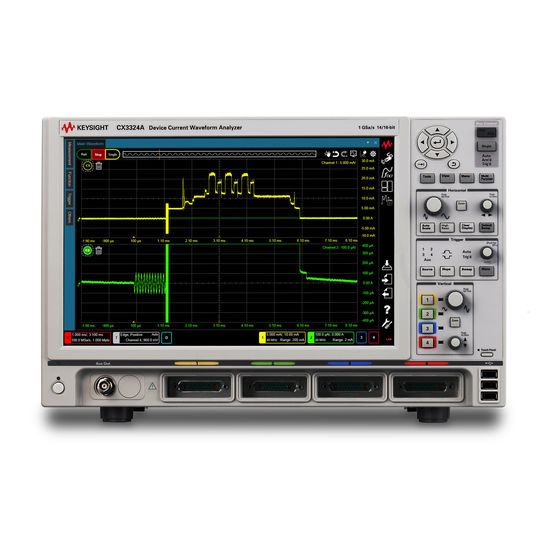
Keysight Technologies CX3300 Series
Device Current Waveform Analyzer
CX3322A 2-Channel Model
CX3324A 4-Channel Model
User's Guide
Table of
Contents
Previous
Page
Next
Page
1
2
3
4
5
Advertisement
Table of Contents
Need help?
Do you have a question about the CX3300 Series and is the answer not in the manual?
Ask a question
Questions and answers
Related Manuals for Keysight CX3300 Series
Measuring Instruments Keysight CX3322A Quick Operation Manual
Cx3300 series device current waveform analyzer 2-channel model 4-channel model (66 pages)
Measuring Instruments Keysight x-series User Reference Manual
Signal analyzer (1138 pages)
Measuring Instruments Keysight X Series Manual
Signal analyzers n9077a & w9077a wlan measurement application measurement guide (119 pages)
Measuring Instruments Keysight X Series Installation Note
Signal analyzers option erc external reference coupling (7 pages)
Measuring Instruments Keysight CXA N9000A Installation Note
Signal analyzer option pc3 single core high performance processor (22 pages)
Measuring Instruments Keysight X Series Measurement Manual
Signal analyzers (73 pages)
Measuring Instruments Keysight CX1105A User Manual
Device current waveform analyzer (112 pages)
Measuring Instruments Keysight CX1103A User Manual
Device current waveform analyzer (112 pages)
Measuring Instruments Keysight CX1101A User Manual
Device current waveform analyzer (112 pages)
Measuring Instruments Keysight 16900 series Installation Manual
External boot drive for keysight logic analysis systems (42 pages)
Measuring Instruments Keysight N2800A User Manual
Keysight n2800a series infiniimax iii series probing system (142 pages)
Measuring Instruments Keysight M9703A Series Configuration And Measurement Instructions
Hardware extension of keysight 89600 vsa software (13 pages)
Measuring Instruments Keysight M9703B Configuration And Measurement Instructions
High-speed digitizers hardware extension of keysight 89600 vsa software (21 pages)
Measuring Instruments Keysight N2787A User Manual
Keysight n2800a series infiniimax iii series probing system (142 pages)
Measuring Instruments Keysight U1583B Operating Instructions
Current clamp (4 pages)
Measuring Instruments Keysight Truevolt Series Operating And Service Manual
Digital multimeters (583 pages)
This manual is also suitable for:
Cx3322a
Cx3324a
Cx1151a
Cx1105a
Cx1104a
Cx1103a
...
Show all
Cx1102a
Cx1101a
Cx1206a
Table of Contents
Print
Rename the bookmark
Delete bookmark?
Delete from my manuals?
Login
Sign In
OR
Sign in with Facebook
Sign in with Google
Upload manual
Upload from disk
Upload from URL


Need help?
Do you have a question about the CX3300 Series and is the answer not in the manual?
Questions and answers