Intrinsyc Open-Q 820 User Manual
Microsom development kit
Hide thumbs
Also See for Open-Q 820:
- User manual (57 pages) ,
- User manual (50 pages) ,
- User manual (44 pages)
Table of Contents
Advertisement
Quick Links
Open-Q™ 820 (APQ8096) / 820Pro (APQ8096SG)
µSOM Development Kit
User Guide
[Document: ITC-01RND1239-UG-001 Version: 1.4]
Your use of this document is subject to and governed by those terms and conditions in the Intrinsyc Purchase an Open-Q 820 µSOM
Development Kit Based on Snapdragon™ 820 Series (APQ8096) Processor and Software License Agreement for the Open-Q 820 µSOM
Development Kit, which you or the legal entity you represent, as the case may be, accepted and agreed to when purchasing an Open-Q
Development Kit from Intrinsyc Technologies Corporation ("Agreement"). You may use this document, which shall be considered part of
the defined term "Documentation" for purposes of the Agreement, solely in support of your permitted use of the Open-Q 820 µSOM
Development Kit under the Agreement. Distribution of this document is strictly prohibited without the express written permission of Intrinsyc
Technologies Corporation and its respective licensors, which they can withhold, condition or delay in its sole discretion.
Intrinsyc is a trademark of Intrinsyc Technologies Corporation., registered in Canada and other countries.
Qualcomm® and Snapdragon™ are trademarks of Qualcomm® Incorporated, registered in the United States and other countries. Other
product and brand names used herein may be trademarks or registered trademarks of their respective owners.
This document contains technical data that may be subject to U.S. and international export, re-export, or transfer ("export") laws. Diversion
contrary to U.S. and international law is strictly prohibited.
Advertisement
Table of Contents

Related Manuals for Intrinsyc Open-Q 820


Summary of Contents for Intrinsyc Open-Q 820
- Page 1 [Document: ITC-01RND1239-UG-001 Version: 1.4] Your use of this document is subject to and governed by those terms and conditions in the Intrinsyc Purchase an Open-Q 820 µSOM Development Kit Based on Snapdragon™ 820 Series (APQ8096) Processor and Software License Agreement for the Open-Q 820 µSOM Development Kit, which you or the legal entity you represent, as the case may be, accepted and agreed to when purchasing an Open-Q Development Kit from Intrinsyc Technologies Corporation (“Agreement”).
- Page 2 25, 35 Updated figure 16 Feb 1, 2017 Added information on GPS antenna Feb 14, 2017 Added information on WiFi/ BT certification Update doc to include 820Pro µSOM development kit. June 7, 2019 Updated USB port descriptions Copyright Intrinsyc Technologies Corporation...
-
Page 3: Table Of Contents
µSOM Block Diagram ................... 13 3.7.3 Hardware Specification ..................14 3.7.4 µSOM RF Specification for WIFI, BT, GPS ............16 Open-Q 820 / 820Pro µSOM Carrier Board........17 3.8.1 Dip switch S10 Configuration Options ............... 17 3.8.2 Carrier Board Expansion Connectors ..............18 3.8.3... - Page 4 Open-Q™ 820 (APQ8096) / 820Pro (APQ8096SG) µSOM Development Kit User Guide Version 1.4 3.8.23 VIP Expansion Header J71.................. 47 3.8.24 USB 2.0 Client Port Operation ................47 3.8.25 USB 2.0 Interface Operation ................48 3.8.26 USB 3.0 Interface Operation ................49 Copyright Intrinsyc Technologies Corporation...
-
Page 5: Introduction
820 (APQ8096) / 820Pro (APQ8096SG) µSOM Development Kit. For more background information on this development kit, visit: www.intrinsyc.com 1.2 Scope This document will cover the following items on the Open-Q 820 / 820Pro µSOM Development Kit: • Block Diagram and Overview • Hardware Features •... -
Page 6: Documents
Open-Q™ 820 (APQ8096) / 820Pro (APQ8096SG) µSOM Development Kit User Guide Version 1.4 2. DOCUMENTS This section lists the supplementary documents for the Open-Q 820/ 820Pro µSOM development kit. 2.1 Applicable Documents REFERENCE TITLE Intrinsyc Purchase and Software License Agreement for the Open-Q Development Kit 2.2 Reference Documents... - Page 7 (Qualcomm® proprietary mostly PMIC / SSBI Companion chip and baseband processor protocol) Universal Asynchronous Receiver UART Transmitter Universal Flash Storage User Identity module Universal Serial Bus USB HS USB High Speed USB SS USB Super Speed Copyright Intrinsyc Technologies Corporation...
-
Page 8: List Of Figures
2.4 List of Figures Figure 1 Assembled Open-Q 820 / 820Pro µSOM Development Kit ..........10 Figure 2 Open-Q 820 / 820Pro µSOM + Carrier Board Block Diagram ..........12 Figure 3 Open-Q 820 / 820Pro µSOM ....................13 Figure 4 µSOM Block Diagram ......................14 Figure 5 J21 12V DC Power Jack ...................... -
Page 9: Open-Q 820 Μsom Development Kit
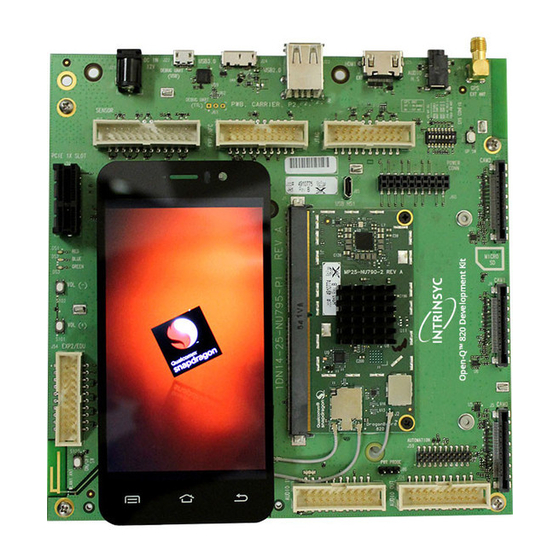
Open-Q™ 820 (APQ8096) / 820Pro (APQ8096SG) µSOM Development Kit User Guide Version 1.4 3. OPEN-Q 820 µSOM DEVELOPMENT KIT 3.1 Introduction The Open-Q 820 / 820Pro µSOM provides a quick reference or evaluation platform for Qualcomm’s latest 820 series - Snapdragon 820 processor. This kit is suited for Android / ™... - Page 10 AC power adapter and HDMI cable Figure 1 Assembled Open-Q 820 / 820Pro µSOM Development Kit The development kit comes with Android software pre-programmed on the CPU board (µSOM). Please contact Intrinsyc for availability of camera modules, sensor boards, and other accessories: sales@intrinsyc.com...
-
Page 11: Hardware Identification Label
Note: Please retain the µSOM and carrier board serial number for warranty purposes. 3.6 System Block Diagram The Open-Q 820 / 820Pro µSOM development platform consists of three major components o Open-Q 820 / 820Pro µSOM o Carrier board for I/O and connecting with external peripherals o Display Adapter Board (additional accessory) The following diagram explains the interconnectivity and peripherals on the development kit. -
Page 12: Open-Q 820 / 820Pro Μsom
TTL to UART JTAG Carrier Board Figure 2 Open-Q 820 / 820Pro µSOM + Carrier Board Block Diagram 3.7 Open-Q 820 / 820Pro µSOM The µSOM provides the basic common set of features with minimal integration efforts for end users. -
Page 13: Μsom Mechanical Properties
3.7.2 µSOM Block Diagram The Open-Q 820 / 820Pro µSOM measuring 25mm x 50mm is where all the processing occurs. It is connected to the carrier via three 100 pin Hirose DF40 connectors. The purpose of these connectors is to bring out essential signals such that other peripherals can be connected to the platform. -
Page 14: Hardware Specification
BPLSs / MPPs / GPIOs BOOT CONFIG UART Open-Q™ 820 / JTAG 820Pro µSOM Carrier Board Figure 4 µSOM Block Diagram 3.7.3 Hardware Specification The Open-Q 820 / 820Pro µSOM platform encompasses the following hardware features: Copyright Intrinsyc Technologies Corporation... - Page 15 Open-Q™ 820 (APQ8096) / 820Pro (APQ8096SG) µSOM Development Kit User Guide Version 1.4 Table 3.7-1 Open-Q 820 / 820Pro µSOM Hardware Features Subsystem / Feature Set Description Specification Connectors Chipset APQ8096 or Qualcomm® Snapdragon™ Qualcomm® Kyro CPU, quad APQ8096SG 820 Processor core, 64-bit ARM V8 compliant processor, 2.2GHz (2.34GHz...
-
Page 16: Μsom Rf Specification For Wifi, Bt, Gps
WGR7640: GPS Front End WGR7640 is the primary GPS radio interface used on the Open-Q 820 µSOM development kit. This provides the RF capabilities for GNSS functions. It has both digital and RF interfaces. Digital interface is required for configuration and status of the APQ8096 baseband processor. -
Page 17: Open-Q 820 / 820Pro Μsom Carrier Board
3.8.1 Dip switch S10 Configuration Options There is a DIP switch S10 on the top side of the Open-Q 820 / 820Pro µSOM carrier board. The 8-bit switch allows the user to control the system configuration and boot options. Table 3.8-1 below outlines the pin outs and connections of this DIP switches. -
Page 18: Carrier Board Expansion Connectors
2lineout and 1 headset drivers (with Qualcomm® ANC technology) 3-Digital Microphone via Audio expansion Digital Audio header For Digital audio input audio input expansion Supported using for Digital MIC, I2S header WCD9335 codec, Slim bus interface. Copyright Intrinsyc Technologies Corporation... - Page 19 Hub USB Recovery USB 2.0 via USB1 Vertical Micro B connector USB recovery/ debug through USB switch (for factory purposes only) WLAN Antenna 2X PCB Antenna 2.4 – 5.1 GHz Antenna to µSOM WiFi module Copyright Intrinsyc Technologies Corporation...
- Page 20 Can be used for other purposes. PCI Express Slot PCI Express for external PCIe1 v2.1 To connect an Ethernet peripheral connectivity Supports half card only PCIe card board to Supports 10W card via support Ethernet. power supply Copyright Intrinsyc Technologies Corporation...
-
Page 21: Dc Power Input J21
3.8.3 DC Power Input J21 The Open-Q 820 / 820Pro µSOM development kit power source connects to the 12V DC power supply jack J21. Starting from the power jack, the 12V power supply branches off into different voltage rails via step down converters on the carrier board and PMIC on the µSOM. - Page 22 • Battery charging. Please see section below for additional information on battery support. • Please note that support for battery charging over external charger is not implemented in the design. Please contact Intrinsyc for such customization. PM8996 PMIC is used for: • Source various regulated power rails •...
-
Page 23: Battery Header J300
3.8.4 Battery Header J300 Figure 6 J300 Battery Header The Open-Q 820 / 820Pro µSOM development platform can also power the µSOM with a single cell Lithium-Ion Polymer (LiPo) battery pack which connects to header J300. The purpose of this header is to be used by the end user to develop a battery charging solution, including battery characterization. -
Page 24: Power Probe Header J86
PC, the following cable (or similar) is needed http://www.digikey.ca/product-detail/en/TTL-232R-RPI/768-1204-ND/4382044 Description Signal FTDI RPI cable connection APQ UART RX (GPIO5) BLSP8_UART_RX J61[1] Orange APQ UART TX (GPIO4) BLSP8_UART_TX J61[2] Yellow J61[3] Black Copyright Intrinsyc Technologies Corporation... -
Page 25: Debug Serial Uart Over Usb J22
3.8.7 Debug Serial UART over USB J22 Figure 9 J22 Debug UART over USB The UART connection used on the Open-Q 820 / 820Pro µSOM is a USB micro B connector (J22). This debug UART is available over USB via the FTDI FT232RQ chip on the carrier board. - Page 26 GPIO119 J53[17 J53[18 SSC SPI-1 chip SSC_SPI_1_CS_N J53[19 SSC SPI-1 SSC_SPI_1_MOS J53[20 select 1 data master out/ slave in SSC SOI-1 clock SSC_SPI_1_CLK J53[21 SSC SPI-1 SSC_SPI_1_MIS J53[22 data master in/ slave out Copyright Intrinsyc Technologies Corporation...
- Page 27 Note that there is an unpopulated Gen-10 connector header (J55) footprint at the bottom of the carrier board. Install the Samtec (part number: QSH-030-01-L-D-A) connector here if needed. Figure 11 J55 Gen-10 Sensor Connector (Samtec QSH-030 series) Copyright Intrinsyc Technologies Corporation...
-
Page 28: Education / Gpio Header J54 (Exp2)
Pin NO Description Signal Pin NO J54[1] VREG_S4A 1.8V VREG_S4A_1P8 J54[2] voltage regulator max 150mA BLSP1_3_3P3(3.3V) BLSP1_SPI_ J54[3] VDD_EXP2 (Default VDD_EXP2 J54[4] MOSI (APQ- 3.3V Power Supply) GPIO0) max 300mA BLSP1_2_3P3(3.3V) BLSP1_SPI_ J54[5] J54[6] MISO (APQ- GPIO1) Copyright Intrinsyc Technologies Corporation... -
Page 29: Anc Headset Jack J27
3.8.10 ANC Headset Jack J27 Figure 13 ANC Headphone Jack The ANC headset jack (J27) is a special 3.5mm TRRS jack with ANC capabilities. It is backwards compatible with standard headset jacks. Please contact Intrinsyc at sales@intrinsyc.comfor compatible ANC headsets. Copyright Intrinsyc Technologies Corporation... -
Page 30: Audio Inputs Expansion Header J50
3. Voltage rails to support analog and digital mics For details on how to connect analog or digital microphones to system, refer to sections 4.1.9 on Open-Q 820 / 820Pro µSOM Development Kit µSOM Technical Note19 (document R-3). The table below outlines the pin out information of the audio inputs expansion header J50: Table 3.8-5 Audio Inputs Expansion Header J50 Pin out... -
Page 31: Audio Outputs Expansion Header J26
Analog audio line out CDC_LINE_OU J26[1] Analog audio line CDC_LINE_OUT1_N J26[2] 1, positive differential T1_P negative output differential output Analog audio line out CDC_LINE_OU J26[3] Analog audio line CDC_LINE_OUT2_N J26[4] 2, positive differential T2_P negative output differential output Copyright Intrinsyc Technologies Corporation... -
Page 32: On Board Pcb Wlan Antenna
3.8.13 On Board PCB WLAN Antenna The Open-Q 820 / 820Pro µSOM carrier board has two on board WLAN PCB antennas that connects to the QCA6174 WiFi module on the µSOM via coaxial cables that attaches to MH4L receptacles. These antennas connect to the µSOM in the following configuration:... -
Page 33: External And On-Board Pcb Gps Antenna
Figure 16 On Board PCB Antennas 3.8.14 External and on-Board PCB GPS Antenna The Open-Q 820 / 820Pro µSOM carrier board allows user the flexibility of using an external (via SMA connector) or an on-board PCB GPS antenna. Depending on which antenna is used, dip switch S10 needs to be configured (see table below for details). -
Page 34: Hdmi Connector J25
Can support external backlight driver control and power PMI8996 backlight driver supports three LED strings of up to 30mA each with 28V maximum boost voltage The Open-Q 820 / 820Pro µSOM development platform can support the following display combinations: MIPI DSI... -
Page 35: Display Connector J2
Open-Q™ 820 (APQ8096) / 820Pro (APQ8096SG) µSOM Development Kit User Guide Version 1.4 Please note that the Open-Q 820 / 820Pro µSOM Development kit is for evaluation purposes only and may not be HDMI compliant. 3.8.17 Display Connector J2 Figure 18 100-Pin Display Connector... - Page 36 LCD that comes preinstalled on the display board. The following figure illustrates the interfacing connectors on the display board. Note: The display board comes as an additional add-on to the Open-Q 820 / 820Pro µSOM development kit. To purchase this, please visit http://shop.intrinsyc.com...
- Page 37 Open-Q™ 820 (APQ8096) / 820Pro (APQ8096SG) µSOM Development Kit User Guide Version 1.4 LCD Display Panel (Top) ERM8 Display Adaptor Board (Bott) Figure 19 Display Board Block Diagram Copyright Intrinsyc Technologies Corporation...
- Page 38 J2 on the carrier board for this configuration to work. Carrier Board Display Adaptor Board LCD Display ERF8 Panel (Top) DSI0 DSI0 DSI1 DSI1 ERM8 Via MXM Connector DSI0 (Top) (Bott) Figure 20 Display Board Default Configuration Copyright Intrinsyc Technologies Corporation...
-
Page 39: Pci Express 1X Slot J30
Note: The display above when mounted on the Intrinsyc Open-Q 820 Display Adapter is meant to work with the carrier board. Altering the use of this LCD panel is not recommended. 3.8.18 PCI Express 1X Slot J30 The PCI Express slot J30 used on the Open-Q 820 / 820Pro µSOM development kit is a... -
Page 40: Mini Pci Express Connector J72
Low profile: 2.536” (64.4mm) 3.8.19 Mini PCI Express Connector J72 The Open-Q 820 / 820Pro µSOM development kit also supports the use of a PCI Express mini card. The primary difference between a PCI Express 1X card and a PCI Express mini card is the unique form factor optimized for mobile computing platforms. -
Page 41: Camera Connectors
Figure 23 Mounting holes for Mini PCIe Connector 3.8.20 Camera Connectors The Open-Q 820 / 820Pro µSOM development kit supports three 4-lane MIPI CSI camera interfaces via three separate JAE 41-pin connectors. The following are some features of the camera connectors: •... - Page 42 Power output. Connected to PM8996 VREG_LVS1A switch output. Default is +1.8V. Maximum current 300mA Ground FLASH_STROBE_ FLASH_STROBE_E FLASH_STROBE_EN Output. Connected to EN (APQ_GPIO22) N (DNP) (DNP) (APQ_GPIO22) APQ8096 Default use is for (APQ_GPIO22) camera flash strobe enable Copyright Intrinsyc Technologies Corporation...
- Page 43 Input. MIPI CSI0 / CSI1 / CSI2 data lane 2 MIPI_CSI0_LANE2 MIPI_CSI1_LANE2_ MIPI_CSI2_LANE2_P Input. MIPI CSI0 / CSI1 / CSI2 data lane 2 Ground MIPI_CSI0_LANE3 MIPI_CSI1_LANE3_ MIPI_CSI2_LANE3_P Input. MIPI CSI0 / CSI1 / CSI2 data lane 3 Copyright Intrinsyc Technologies Corporation...
- Page 44 Note: A connection from the camera connectors on the carrier board to the Intrinsyc camera adapter board is established by a 41-pin cable assembly from JAE Electronics (part number JF08R0R041020MA) The following table shows the combinations of camera usage for different use cases Table 3.8.20-2.
-
Page 45: Power Header Via 20 Pin Connector J60
Description Signal Pin NO Description Signal Pin NO 1.05V MB_ELDO_CAM0_DVDD J60[1] 2.85V power VREG_L17A_2P8 J60[2] power rail rail for for camera camera 0 (AVDD) 2.8V power VREG_L23A_2P8 J60[3] J60[4] rail for camera 0, 2 (VDD) Copyright Intrinsyc Technologies Corporation... -
Page 46: Ethernet Avb Expansion Header J73
3.8.22 Ethernet AVB Expansion Header J73 Figure 26 J73 Ethernet AVB Expansion Header This header is used for interfacing with automotive peripherals via Ethernet AVB standard. Note that this is used for Intrinsyc internal testing and is not supported. Copyright Intrinsyc Technologies Corporation... -
Page 47: Vip Expansion Header J71
Figure 27 J71 VIP Expansion Header This header is used for interfacing with Qualcomm® legacy automotive VIP boards. Note that this is for Intrinsyc internal testing and is not supported. 3.8.24 USB 2.0 Client Port Operation Figure 28 J24 USB2.0 for ADB J24 allows the development kit to communicate with a host PC using the Android Debug Bridge (ADB). -
Page 48: Usb 2.0 Interface Operation
To access this port, switch S1 position 2 needs to be set to the on position. Switch S1 is in the off position by default. Figure 30 S1 Board Configuration Switch (on Bottom of Development Kit) Copyright Intrinsyc Technologies Corporation... -
Page 49: Usb 3.0 Interface Operation
Akasa dual USB3.0 PCI slow connector with 19-pin connector (P/N# AK-CBUB17- 40BK). Note that this header only consists of 19 pins. Similar to the connector J23, switch S1 position 2 needs to be set to the off position. Copyright Intrinsyc Technologies Corporation... - Page 50 Open-Q™ 820 (APQ8096) / 820Pro (APQ8096SG) µSOM Development Kit User Guide Version 1.4 Figure 32 J2600 USB3.0 Expansion Connector Copyright Intrinsyc Technologies Corporation...
- Page 51 Mouser Electronics Authorized Distributor Click to View Pricing, Inventory, Delivery & Lifecycle Information: Intrinsyc QC-DB-I20003...
Need help?
Do you have a question about the Open-Q 820 and is the answer not in the manual?
Questions and answers