Intrinsyc LANTRONIX Open-Q 820 User Manual
Msom development kit
Hide thumbs
Also See for LANTRONIX Open-Q 820:
- User manual (50 pages) ,
- User manual (51 pages) ,
- User manual (44 pages)
Advertisement
Quick Links
Advertisement

Related Manuals for Intrinsyc LANTRONIX Open-Q 820


Summary of Contents for Intrinsyc LANTRONIX Open-Q 820
- Page 1 Open-Q™ 820/ 820Pro µSOM Development Kit User Guide Part Number PMD-00043 Revision A August 2020...
- Page 2 Your use of this document is subject to and governed by those terms and conditions in the Intrinsyc Purchase an Open-Q 820 µSOM Development Kit Based on Qualcomm™ APQ8096 Processor and Software License Agreement for the Open-Q 820 µSOM Development Kit, which you or the legal entity you represent, as the case may be, accepted and agreed to when purchasing an Open-Q Development Kit from Intrinsyc Technologies Corporation (“Agreement”).
- Page 3 Updated USB port descriptions August 2020 Initial Lantronix document. Added Lantronix document part number, Lantronix logo, branding, contact information, and links. For the latest revision of this product document, please go to: http://tech.intrinsyc.com. Open-Q™ 820 / 820Pro µSOM Dev Kit User Guide...
- Page 4 Contents 1 Introduction Purpose ____________________________________________________________ 11 Scope _____________________________________________________________ 11 Intended Audience ___________________________________________________ 11 2 Documents Applicable Documents _________________________________________________ 7 Reference Documents _________________________________________________ 7 Terms and Acronyms __________________________________________________ 7 List of Figures ________________________________________________________ 9 List of Tables ________________________________________________________ 9 3 Open-Q 820 µSOM Development Kit Introduction _________________________________________________________ 11 Development Platform Notice ___________________________________________ 11 Anti-Static Handling Procedures _________________________________________ 11...
- Page 5 3.9.16 HDMI Connector J25 _____________________________________________ 40 3.9.17 Display Connector J2 _____________________________________________ 41 3.9.18 PCI Express 1X Slot J30 __________________________________________ 45 3.9.19 Mini PCI Express Connector J72 ____________________________________ 46 3.9.20 Camera Connectors ______________________________________________ 47 3.9.21 Power Header via 20 Pin Connector J60 ______________________________ 52 3.9.22 Ethernet AVB Expansion Header J73 ________________________________ 54 3.9.23...
- Page 6 The purpose of this user guide is to provide primary technical information on the Open-Q™ 820 / 820Pro µSOM Development Kit. For more background information on this development kit, visit: https://www.intrinsyc.com/snapdragon- embedded-development-kits/open-q-820-usom-development-kit/ 1.2 Scope This document will cover the following items on the Open-Q 820 / 820Pro µSOM Development Kit: Block Diagram and Overview •...
- Page 7 This section lists the supplementary documents for the Open-Q 820/ 820Pro µSOM development kit. 2.1 Applicable Documents Reference Title Intrinsyc Purchase and Software License Agreement for the Open-Q Development 2.2 Reference Documents Reference Title Hardware Document Set for the Qualcomm™ APQ8096/AP8096SG based Open- Q Development Kit Open-Q 820 / 820Pro Schematics (µSOM, Carrier)
- Page 8 Documents Term and acronyms Definition FWVGA Full Wide Video Graphics Array Global Positioning system HDMI High Definition Media Interface HSIC High Speed Inter Connect Bus JTAG Joint Test Action Group Low Noise Amplifier MIPI Mobile Industry processor interface Multi-Purpose Pin Near Field Communication Radio Frequency SATA...
- Page 9 Documents 2.4 List of Figures Figure 1 Assembled Open-Q 820 / 820Pro µSOM Development Kit ........... 12 Figure 2 Open-Q 820 / 820Pro µSOM + Carrier Board Block Diagram ..........14 Figure 3 Open-Q 820 / 820Pro µSOM ....................15 Figure 4 µSOM Block Diagram ......................
- Page 10 Documents Table 3.8.20-1. MIPI CSI Camera Connector Pinouts (J5,J4,J3) ............48 Table 3.8.20-2. MIPI CSI Camera Use Cases ..................51 Open-Q™ 820 / 820Pro µSOM Dev Kit User Guide...
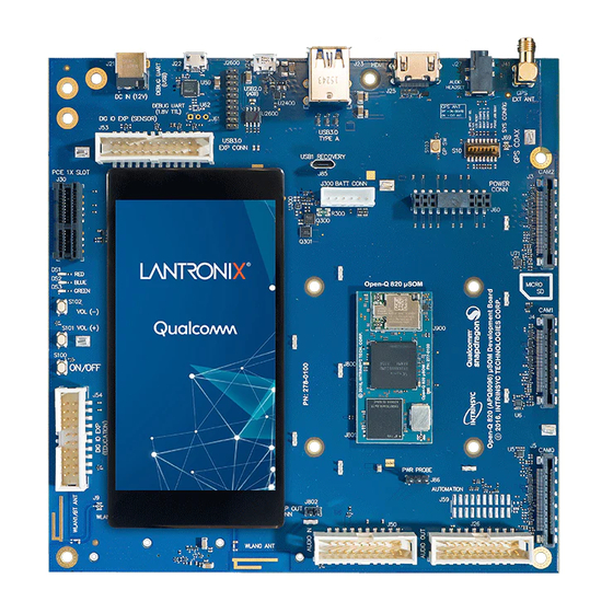
- Page 11 Open-Q 820 µSOM Development Kit 3 Open-Q 820 µSOM Development Kit 3.1 Introduction The Open-Q 820 / 820Pro µSOM provides a quick reference or evaluation platform for Qualcomm’s latest 820 series - Qualcomm APQ8096 processor. This kit is suited for Android / Linux application developers, OEMs, ™...
- Page 12 Open-Q 820 µSOM Development Kit Figure 1 Assembled Open-Q 820 / 820Pro µSOM Development Kit The development kit comes with Android software pre-programmed on the CPU board (µSOM). Please contact Lantronix for availability of camera modules, sensor boards, and other accessories: sales@lantronix.com Open-Q™...
- Page 13 • Serial Number • WIFI MAC address Refer to http://tech.intrinsyc.com/projects/serialnumber/wiki for more details about locating the serial number, as this will be needed to register the development kit. To register a development kit, please visit https://tech.intrinsyc.com/account/register. Mini-ITX form-factor carrier board: Serial Number •...
- Page 14 Open-Q 820 µSOM Development Kit LEDs APQ8096 / (optional) APQ8096SG 3.8V BUCK Jack IQ + SSBI Antenna WGR7640 VBAT PMi8996 PCIe0 POWER QCA6174 BT/WiFi UART WiFi/BT Anetnnas RST/Vol - (2.5/5GHz) SPMI coax PM8996 VOL + 1 lane GENERAL 32 to 64GB GPIO120 PCIe1 PCIe 2.1...
- Page 15 Open-Q 820 µSOM Development Kit 50 mm 25 mm Figure 3 Open-Q 820 / 820Pro µSOM 3.7.1 µSOM Mechanical Properties Area 12.5 cm (25 mm x 50 mm) Interface 3 x 100-pins Hirose DF40 connectors (B2B Connector). Thermal A top side heat sink is installed by default. Shielding A top side shield can for the GPS front end is installed by default.
- Page 16 Open-Q 820 µSOM Development Kit Carrier Board APQ8096 / LEDs APQ8096SG Power Circuit IQ + SSBI WGR7640 VBAT PCIe0 QCA6174 PMi8996 UART WiFi/BT SPMI PM8996 1 lane UFS 32 to 64GB PCIe 2.1 PCIe1 SDC1 4-bit SDIO SDC2 PCIe2 PCIe 2.1 DSI 0 4L DSI DSI 1...
- Page 17 Open-Q 820 µSOM Development Kit 3.8.1 Hardware Specification The Open-Q 820 / 820Pro µSOM platform encompasses the following hardware features: Table 3.7-1 Open-Q 820 / 820Pro µSOM Hardware Features Subsystem / Feature Set Description Specification Connectors Chipset APQ8096 or Qualcomm Processor Qualcomm®...
- Page 18 Open-Q 820 µSOM Development Kit Subsystem / Feature Set Description Specification Connectors Interfaces 3 x MIPI CSI Camera Connectors MIPI Alliance Specification v1.0 CSI0, CSI1, CSI2 2 x USB HS & 1 x 1 x USB3.1 header, 1 x dual USB3.1 &...
- Page 19 Open-Q 820 µSOM Development Kit The µSOM WiFi/BT module has received regulatory certifications (see FCC ID: 2AFDI-ITCNFA324 for details). Please note that the on-board PCB antennas were not the antennas used for the µSOM WiFi/BT module certification. Refer to the certification documents for the WiFi/ BT module (see R-4) for information regarding the test configurations used for certification.
- Page 20 Open-Q 820 µSOM Development Kit 3.9 Open-Q 820 / 820Pro µSOM Carrier Board The Open-Q 820 / 820Pro µSOM Carrier board is a Mini-ITX form factor board with various connectors used for connecting different peripherals. The following are the mechanical properties of the carrier board: Dimensions 289 cm (170mm x 170mm)
- Page 21 Open-Q 820 µSOM Development Kit Function Switch Description Notes BOOT_CONFIG[1] S10-5 Enables APQ boot configuration 1 Default out of the box when DIP switch turned on. configuration is OFF Controlled by APQ-GPIO 102 WATCHDOG S10-6 Enables WATCHDOG_DISABLE Default out of the box _DISABLE when DIP switch turned on.
- Page 22 Open-Q 820 µSOM Development Kit Domain Description Specification Usage Buttons General Purpose SW SMD Button Additional button for button general purpose (connected to APQ_GPIO120) Power Button SMD Button Power Button for Suspend / Resume and Power off Zoom / Volume Keys Volume + key SMD Button Volume +Key...
- Page 23 Open-Q 820 µSOM Development Kit Domain Description Specification Usage Supported using WCD9335 Earpiece via audio Audio expansion Analog Audio header For earpiece output output expansion after signal has been Supported using header processed WCD9335 Haptics driver via audio Audio expansion Analog Audio header For haptics output (ex: output expansion...
- Page 24 Open-Q 820 µSOM Development Kit Domain Description Specification Usage WLAN Antenna 2X PCB Antenna 2.4 – 5.1 GHz Antenna to µSOM WiFi module GPS Antenna PCB Antenna GPS : Antenna to µSOM GPS module 1574.42 MHz – 1576.42 GLONASS : 1587 MHz –...
- Page 25 Open-Q 820 µSOM Development Kit Domain Description Specification Usage Can be used for other purposes. VIP Extension Connector for interfacing 60 pin connector To connect to connector with Qualcomm® legacy Qualcomm® legacy automotive VIP boards automotive VIP boards (for Lantronix internal use only –...
- Page 26 Open-Q 820 µSOM Development Kit Domain Description Specification Usage Support for 3D • camera configuration • Separate I2C / CCI control MIPI Alliance Specification v1.00 for Camera Serial Interface Power Probe Header 3 pin power probe header Sense lines connected To measure current across 0.005 Ohm resistor consumption of µSOM...
- Page 27 Open-Q 820 µSOM Development Kit Figure 5 J21 12V DC Power Jack The µSOM consists of 2 PMIC modules. Functionalities of the 2 modules are outlined below. PMI8996 PMIC is used for: Source various regulated power rails • Battery charging. Please see section below for additional information on battery support. •...
- Page 28 Open-Q 820 µSOM Development Kit 3.9.4 Battery Header J300 Figure 6 J300 Battery Header The Open-Q 820 / 820Pro µSOM development platform can also power the µSOM with a single cell Lithium- Ion Polymer (LiPo) battery pack which connects to header J300. The purpose of this header is to be used by the end user to develop a battery charging solution, including battery characterization.
- Page 29 Open-Q 820 µSOM Development Kit Note that the software that is shipped with the development kit does NOT support battery charging. Please visit the Lantronix support site and follow the instructions for preparing the platform to support battery charging. 3.9.5 Power Probe Header J86 Figure 7 J86 Power Probe Header The power probe header is used to sense/ monitor the current on the 3.8V power rail going into the µSOM.
- Page 30 Open-Q 820 µSOM Development Kit Description Signal FTDI RPI cable connection APQ UART RX (GPIO5) BLSP8_UART_RX J61[1] Orange APQ UART TX (GPIO4) BLSP8_UART_TX J61[2] Yellow J61[3] Black 3.9.7 Debug Serial UART over USB J22 Figure 9 J22 Debug UART over USB The UART connection used on the Open-Q 820 / 820Pro µSOM is a USB micro B connector (J22).
- Page 31 Open-Q 820 µSOM Development Kit 3.9.8 Sensor IO Expansion Header J53 Figure 10 J53 Sensor Expansion Header The sensor expansion header J53 allows for a 24-pin connection to an optional sensor board. If user application does not require a sensor, then this header can be used for other applications that require I2C or GPIO input and output connections.
- Page 32 Open-Q 820 µSOM Development Kit Description Signal Description Signal Sensor IO PWR 1.8 SENS_IO_PWR J53[7] Sensor SENS_ANA_PWR J53[8] Analog power VREG_LVS2A_1P supply from 8 power supply VREG_L19A regulator (Digital) 2.85V or 3.3V (If R160 populated) J53[9] J53[10 HRM interrupt/ HRM_INT J53[11 Touch screen TS_INT0...
- Page 33 Open-Q 820 µSOM Development Kit Note that there is an unpopulated Gen-10 connector header (J55) footprint at the bottom of the carrier board. Install the Samtec (part number: QSH-030-01-L-D-A) connector here if needed. Figure 11 J55 Gen-10 Sensor Connector (Samtec QSH-030 series) Open-Q™...
- Page 34 Open-Q 820 µSOM Development Kit 3.9.9 Education / GPIO header J54 (EXP2) Figure 12 J54 Education / GPIO header Education/ GPIO header expansion J54 is a 20 pin connector that provides access to BLSP1 signals with level shifters. It is ideally used for connecting external peripherals such as microcontrollers and any other devices that are based on I2C, SPI, UART, UIM and GPIO.
- Page 35 Open-Q 820 µSOM Development Kit Description Signal Pin NO Description Signal Pin NO BLSP1_2_3P3(3.3V) BLSP1_SPI_ J54[5] J54[6] MISO (APQ- GPIO1) BLSP1_1_3P3(3.3V) BLSP1_SPI_C J54[7] PM8996 MPP GPIO4 PM_MPP04 J54[8] S_N (APQ- GPIO2) BLSP1_0_3P3(3.3V) BLSP1_SPI_C J54[9] J54[10] LK (APQ- GPIO3) J54[11] J54[12] J54[13] J54[14] J54[15]...
- Page 36 Open-Q 820 µSOM Development Kit 3.9.11 Audio Inputs Expansion Header J50 Figure 14 J50 Audio Inputs Expansion Header This header expansion provides the following audio inputs: 1. 3 digital mic inputs (each can support 2 digital microphones) 2. 3 analog mics 3.
- Page 37 Open-Q 820 µSOM Development Kit Description Signal Pin NO Description Signal Pin NO J50[11] J50[12] Clock for digital MIC 1 CDC_DMIC_CL J50[13] Clock for digital MIC CDC_DMIC_CLK1 J50[14] and 2 3 and 4 Digital MIC 1 and 2 CDC_DMIC_DA J50[15] Digital MIC 3 and 4 CDC_DMIC_DAT J50[16]...
- Page 38 Open-Q 820 µSOM Development Kit Table 3.8-6 Audio Outputs Expansion Header J26 Pin out Description Signal Pin NO Description Signal Pin NO Analog audio line out CDC_LINE_OU J26[1] Analog audio line CDC_LINE_OUT1_N J26[2] 1, positive differential T1_P negative output differential output Analog audio line out CDC_LINE_OU J26[3]...
- Page 39 Open-Q 820 µSOM Development Kit ANT1 ANT2 Figure 16 On Board PCB Antennas 3.9.14 External and on-Board PCB GPS Antenna The Open-Q 820 / 820Pro µSOM carrier board allows user the flexibility of using an external (via SMA connector) or an on-board PCB GPS antenna. Depending on which antenna is used, dip switch S10 needs to be configured (see table below for details).
- Page 40 Open-Q 820 µSOM Development Kit Backlight LED Can support external backlight driver control and power PMI8996 backlight driver supports three LED strings of up to 30mA each with 28V maximum boost voltage The Open-Q 820 / 820Pro µSOM development platform can support the following display combinations: MIPI DSI 1 x 4lane DSI0 + 1 x 4lane DSI1 1 x 8 lane combining DIS0 and DSI1 for up to 4K resolution...
- Page 41 Open-Q 820 µSOM Development Kit 3.9.17 Display Connector J2 Figure 18 100-Pin Display Connector The 100-pin display connector provides the following features/ pin-outs that enables the development kit to connect to a MIPI DSI panel/ device: Note: Please refer to the carrier schematic and display board tech note when designing a custom display board.
- Page 42 The following figure illustrates the interfacing connectors on the display board. Note: The display board comes as an additional add-on to the Open-Q 820 / 820Pro µSOM development kit. To purchase this, please visit http://shop.intrinsyc.com or contact Lantronix at sales@lantronix.com for details.
- Page 43 Open-Q 820 µSOM Development Kit LCD Display Panel (Top) ERM8 Display Adaptor Board (Bott) Figure 19 Display Board Block Diagram Open-Q™ 820 / 820Pro µSOM Dev Kit User Guide...
- Page 44 Open-Q 820 µSOM Development Kit Connecting the Display Board to the Development Kit This configuration allows the user to use the preinstalled LCD display that comes with the display adaptor board. As shown in the block diagram below, the MIPI DSI0 lines, which come from the 100-pin ERM8 connector, directly connects to the LCD panel.
- Page 45 Open-Q 820 µSOM Development Kit 3.9.17.1 LCD display panel The LCD panel comes preinstalled on the Open-Q 820 / 820Pro display adaptor board. Below are the Panel specifications: Resolution: 480x854 • • LCD Type: IPS • PCAP touch panel with cover glass No of Lanes: 1 x 2 lane MIPI DSI interface via Display Board.
- Page 46 Open-Q 820 µSOM Development Kit Power Rail Low Power High Power 3.3 V ± 9% 3 A Max 3A Max 12 V ± 8% 0.5 A Max 2.1 A max 3.3 Vaux ± 9% 375mA Max 375mA Max • PCIe card Mechanical Specifications: Card length: Half card: 6.6”...
- Page 47 Open-Q 820 µSOM Development Kit Mounting holes for half size card (not populated by default) Mounting holes for full size card Figure 23 Mounting holes for Mini PCIe Connector 3.9.20 Camera Connectors The Open-Q 820 / 820Pro µSOM development kit supports three 4-lane MIPI CSI camera interfaces via three separate JAE 41-pin connectors.
- Page 48 Open-Q 820 µSOM Development Kit All camera CSI connectors are on the carrier board edge • Self-regulated camera modules can be powered with 3.3V power (MB_VREG_3P3) • Uses JAE FI-RE41S-VF connector for exposing MIPI, CLK, GPIOs and Power rails. • Please use JAE FI-RE41S-HF to mate with the camera connectors on the carrier board •...
- Page 49 Open-Q 820 µSOM Development Kit Pin# CAM0 (J5) CAM1 (J4) CAM2 (J3) Description +1.8V. Maximum current 300mA Ground FLASH_STROBE_ FLASH_STROBE_E FLASH_STROBE_EN Output. Connected to EN (APQ_GPIO22) N (DNP) (DNP) (APQ_GPIO22) APQ8096 Default use is for (APQ_GPIO22) camera flash strobe enable Install R42 to access Install R36 to access signal...
- Page 50 Open-Q 820 µSOM Development Kit Pin# CAM0 (J5) CAM1 (J4) CAM2 (J3) Description MIPI_CSI0_LANE0 MIPI_CSI1_LANE0_ MIPI_CSI2_LANE0_N Input. MIPI CSI0 / CSI1 / CSI2 data lane 0 MIPI_CSI0_LANE0 MIPI_CSI1_LANE0_ MIPI_CSI2_LANE0_P Input. MIPI CSI0 / CSI1 / CSI2 data lane 0 Ground MIPI_CSI0_CLK_N MIPI_CSI1_CLK_N MIPI_CSI2_CLK_N...
- Page 51 Open-Q 820 µSOM Development Kit Pin# CAM0 (J5) CAM1 (J4) CAM2 (J3) Description CAM_IRQ CAM_IRQ (DNP) CAM_IRQ (DNP) Input. Connected to APQ8096 GPIO24. (APQ_GPIO24) (APQ_GPIO24) (APQ_GPIO24) CAM_IRQ signal Install R40 to access Install R46 to access signal signal CAM0_MCLK3 CAM1_MCLK3 CAM2_MCLK3 Output.
- Page 52 Open-Q 820 µSOM Development Kit CSI PHY Use case Comment 2 x Camera of 1 lane each CSI0 + CSI1 Up to 4 lane 3D 4 lane 3D use case / Dual 4 lane configuration CSI 2 Up to 1 lane 3D 1 lane 3D use case / Dual 1 lane configuration CSI0 + CSI1 + CSI2 Up to 4 lane...
- Page 53 Open-Q 820 µSOM Development Kit Description Signal Pin NO Description Signal Pin NO camera 0, 2 (VDD) J60[5] 3.3V power MB_VREG_3P3 J60[6] rail for camera 0, 1, 1.05V MB_ELDO_CAM1_DVDD J60[7] 2.85V power VREG_L18A_2P85 J60[8] power rail rail for for camera camera 1 (AVDD) 2.8V power...
- Page 54 Open-Q 820 µSOM Development Kit 3.9.22 Ethernet AVB Expansion Header J73 Figure 26 J73 Ethernet AVB Expansion Header This header is used for interfacing with automotive peripherals via Ethernet AVB standard. Note that this is used for Lantronix internal testing and is not supported. 3.9.23 VIP Expansion Header J71 Figure 27 J71 VIP Expansion Header...
- Page 55 Open-Q 820 µSOM Development Kit 3.9.24 USB 2.0 Client Port Operation Figure 28 J24 USB2.0 for ADB J24 allows the development kit to communicate with a host PC using the Android Debug Bridge (ADB). This port is a client mode port only and can be used simultaneously with the USB3.0 SuperSpeed ports.
- Page 56 Open-Q 820 µSOM Development Kit Figure 30 S1 Board Configuration Switch (on Bottom of Development Kit) 3.9.26 USB 3.0 Interface Operation Figure 31 J23 USB3.0 Host Ports J23 allows the development kit to communicate as a SuperSpeed host. This is a dual stacked USB3.0 Type-A connector.
- Page 57 Open-Q 820 µSOM Development Kit Two additional USB3.0 SuperSpeed ports are located on header J2600. This header allows an end user to design their own daughter card with additional USB ports. In addition to that, this header can be used with the Akasa dual USB3.0 PCI slow connector with 19-pin connector (P/N# AK-CBUB17- 40BK).
Need help?
Do you have a question about the LANTRONIX Open-Q 820 and is the answer not in the manual?
Questions and answers