Table of Contents
Advertisement
Quick Links
Open-Q™ 835 Development Kit based on the
Snapdragon™ 835 (APQ8098) Processor
User Guide
[Document: ITC-01IMP1283-UG-001 Version: 1.0]
Your use of this document is subject to and governed by those terms and conditions in the Intrinsyc Purchase an Open-Q™ 835
Development Kit based on the Snapdragon™ 835 (APQ8098) Processor and Software License Agreement for the Open-Q 835
Development Kit, which you or the legal entity you represent, as the case may be, accepted and agreed to when purchasing an Open-Q
Development Kit from Intrinsyc Technologies Corporation ("Agreement").
You may use this document, which shall be considered part
of the defined term "Documentation" for purposes of the Agreement, solely in support of your permitted use of the Open-Q 835
Development Kit under the Agreement. Distribution of this document is strictly prohibited without the express written permission of
Intrinsyc Technologies Corporation and its respective licensors, which they can withhold, condition or delay in its sole discretion.
Intrinsyc is a trademark of Intrinsyc Technologies Corporation., registered in Canada and other countries.
Qualcomm® and Snapdragon™ are trademarks of Qualcomm® Incorporated, registered in the United States and other countries. Other
product and brand names used herein may be trademarks or registered trademarks of their respective owners.
This document contains technical data that may be subject to U.S. and international export, re-export, or transfer ("export") laws.
Diversion contrary to U.S. and international law is strictly prohibited.
Advertisement
Table of Contents

Related Manuals for Intrinsyc Open-Q 835


Summary of Contents for Intrinsyc Open-Q 835
- Page 1 [Document: ITC-01IMP1283-UG-001 Version: 1.0] Your use of this document is subject to and governed by those terms and conditions in the Intrinsyc Purchase an Open-Q™ 835 Development Kit based on the Snapdragon™ 835 (APQ8098) Processor and Software License Agreement for the Open-Q 835 Development Kit, which you or the legal entity you represent, as the case may be, accepted and agreed to when purchasing an Open-Q Development Kit from Intrinsyc Technologies Corporation (“Agreement”).
- Page 2 Open-Q™ 835 Development Kit based on the Snapdragon™ 835 (APQ8098) Processor User Guide Version 1.0 IDENTIFICATION Document Title Open-Q™ 835 Development Kit based on the Snapdragon™ 835 (APQ8098) Processor User Guide Document Number ITC-01IMP1283-UG-001 Version Date May 10, 2017 Revision History REVISION DATE DESCRIPTION PAGES May 10, 2017 Initial Draft Copyright Intrinsyc Technologies Corporation...
-
Page 3: Table Of Contents
Reference Documents ................6 Terms and Acronyms ................6 List of Figures ................... 8 List of Tables ..................... 9 Open-Q 835 DEVELOPMENT KIT ............ 10 Introduction ..................... 10 Development Platform Notice .............. 10 Anti-Static Handling Procedures ............10 Kit Contents ..................... 10 Hardware Identification Label ............... - Page 4 Open-Q™ 835 Development Kit based on the Snapdragon™ 835 (APQ8098) Processor User Guide Version 1.0 3.8.23 GNSS Card ......................41 Copyright Intrinsyc Technologies Corporation...
-
Page 5: Introduction
835 Development Kit based on the Snapdragon™ 835 (APQ8098) Processor. For more background information on this development kit, visit: www.intrinsyc.com 1.2 Scope This document will cover the following items on the Open-Q 835 Development Kit: • Block Diagram and Overview • Hardware Features • Configuration •... -
Page 6: Documents
Open-Q™ 835 Development Kit based on the Snapdragon™ 835 (APQ8098) Processor User Guide Version 1.0 2. DOCUMENTS This section lists the supplementary documents for the Open-Q 835 Development Kit. 2.1 Applicable Documents REFERENCE TITLE Intrinsyc Purchase and Software License Agreement for the Open-Q Development Kit 2.2 Reference Documents... - Page 7 Open-Q™ 835 Development Kit based on the Snapdragon™ 835 (APQ8098) Processor User Guide Version 1.0 UART Universal Asynchronous Receiver Transmitter Universal Flash Storage User Identity module Universal Serial Bus USB HS USB High Speed USB SS USB Super Speed Copyright Intrinsyc Technologies Corporation...
-
Page 8: List Of Figures
Figure 1 Assembled Open-Q 835 Development Kit TOP ..............11 Figure 2 Assembled Open-Q 835 Development Kit BOT ..............12 Figure 3 Open-Q 835 Processor board + Carrier Board Block Diagram ..........13 Figure 4 Open-Q 835 PROCESSOR BOARD ..................14 Figure 5 Open-Q 835 Processor Board Block Diagram............... -
Page 9: List Of Tables
Open-Q™ 835 Development Kit based on the Snapdragon™ 835 (APQ8098) Processor User Guide Version 1.0 2.5 List of Tables Table 3.7-1 Open-Q 835 Processor Board Mechanical Properties ............14 Table 3.7-2 Open-Q 835 Processor Board Hardware Features ............16 Table 3.8-1 Open-Q 835 Carrier Board Mechanical Properties ............18 Table 3.8-2 Dip Switch S2301 HW / SW configuration .............. -
Page 10: Open-Q 835 Development Kit
Open-Q™ 835 Development Kit based on the Snapdragon™ 835 (APQ8098) Processor User Guide Version 1.0 3. OPEN-Q 835 DEVELOPMENT KIT 3.1 Introduction The Open-Q 835 Development Kit provides a quick reference or evaluation platform for Qualcomm’s latest 835 series - Snapdragon 835 processor. This kit is suited for Android / ™... - Page 11 Open-Q™ 835 Development Kit based on the Snapdragon™ 835 (APQ8098) Processor User Guide Version 1.0 o Open-Q 835 Processor board with the Snapdragon 835 (APQ8098) ™ processor main CPU board o Mini-ITX form-factor carrier board for I/O and connecting with external...
-
Page 12: Hardware Identification Label
Open-Q™ 835 Development Kit based on the Snapdragon™ 835 (APQ8098) Processor User Guide Version 1.0 Figure 2 Assembled Open-Q 835 Development Kit BOT The development kit comes with Android software pre-programmed on the CPU board or processor board. Please contact Intrinsyc for availability of camera modules, sensor boards, and other accessories: sales@intrinsyc.com 3.5 Hardware Identification Label... -
Page 13: System Block Diagram
CCI1 Universal Flash UFS2.1,G3,2L Storage SDIO uSD CARD WCD9341(Audio SLIMbus Codec) HDMI HDMI2.0 USB0 RF or GNSS-only Daughter Card UART UART WWAN QLINK Boot Config Figure 3 Open-Q 835 Processor board + Carrier Board Block Diagram Copyright Intrinsyc Technologies Corporation... -
Page 14: Open-Q 835 Processor Board
• WCN3990 Wi-Fi + BT +FM combo chip over SLIMbus, Analog IQ, UART, • 128 GB UFS 2.1. • WCD9341 Audio Codec Figure 4 Open-Q 835 PROCESSOR BOARD 3.7.1 Processor Board Mechanical Properties Table 3.7-1 Open-Q 835 Processor Board Mechanical Properties Area 42 cm (60 mm x 70 mm) Interface 2 x 240-pin high speed board to board connectors. -
Page 15: Processor Board Block Diagram
Open-Q™ 835 Development Kit based on the Snapdragon™ 835 (APQ8098) Processor User Guide Version 1.0 3.7.2 Processor Board Block Diagram The Open-Q 835 Processor board measuring 60mm x 70mm is where all the processing occurs. It is connected to the carrier board via two 100 pin Hirose 240-pin connectors. The purpose of these connectors is to bring out essential signals such that other peripherals can be connected to the platform. -
Page 16: Hardware Specification
Open-Q™ 835 Development Kit based on the Snapdragon™ 835 (APQ8098) Processor User Guide Version 1.0 3.7.3 Hardware Specification The Open-Q 835 Processor Board platform encompasses the following hardware features: Table 3.7-2 Open-Q 835 Processor Board Hardware Features Subsystem / Feature Set... -
Page 17: Processor Board Rf Specification For Wifi, Bt
0 can be connected to 2.4GHz while Antenna 1 can be connected to 5 GHz. For details on connecting the WiFi module to the on-board PCB antennas on the carrier board, refer to section 0 below. For GNSS details, See section 3.8.23 GNSS Card Copyright Intrinsyc Technologies Corporation... -
Page 18: Open-Q 835 Carrier Board
Open-Q™ 835 Development Kit based on the Snapdragon™ 835 (APQ8098) Processor User Guide Version 1.0 3.8 Open-Q 835 Carrier Board The Open-Q 835 Carrier board is a Mini-ITX form factor board with various connectors used for connecting different peripherals. The following are the mechanical properties of the carrier board: Table 3.8-1 Open-Q 835 Carrier Board Mechanical Properties... -
Page 19: Dip Switch S10 Configuration Options
3.8.1 Dip switch S10 Configuration Options There is a DIP switch S2301 on the south top side of the Open-Q 835 carrier board. The 8- bit switch allows the user to control the system configuration and boot options. Table 3.8-1 below outlines the pin outs and connections of this DIP switches. - Page 20 BLSP_TP configuration is OFF Note: BLSP5 is routed to BLSP_TP by default Warning! : Before making any changes to the dip switch, make sure to note down the previous configuration. The default switch settings are above. Copyright Intrinsyc Technologies Corporation...
-
Page 21: Carrier Board Expansion Connectors
Antenna to GNSS module GPS: 1574.42 MHz – 1576.42 MHz GLONASS: 1587 MHz – 1606 MHz COMPASS: 1559.05 to 1563.14MHz Galilei: 4.092MHz BW(centered on 1575.42MHz) 3xLED Red: PMIC Driven Red: General purpose Green: PMIC Driven Green: General purpose Copyright Intrinsyc Technologies Corporation... - Page 22 The information listed below is of particular use for those who want to interface other external hardware devices with the Open-Q 835 Processor board. Before connecting anything to the development kit, please ensure the device meets the specific hardware requirements of the processor.
-
Page 23: Dc Power Input J0701
Open-Q™ 835 Development Kit based on the Snapdragon™ 835 (APQ8098) Processor User Guide Version 1.0 3.8.3 DC Power Input J0701 The Open-Q 835 Development Kit power source connects to the 12V DC power supply jack J0701. Starting from the power jack, the 12V power supply branches off into different voltage rails via step down converters on the carrier board and PMIC on the Processor board. -
Page 24: Battery Header J1001
3.8.4 Battery Header J1001 Figure 8 J1001 Battery Header The Open-Q 835 development platform can also power the Processor board with a single cell Lithium-Ion Polymer (LiPo) battery pack which connects to header J1001. The purpose of this header is to be used by the end user to develop a battery charging solution, including battery characterization. -
Page 25: Rcm Header J0901
Table 3.8-7 J2103 Debug UART Header Pin out Description Signal FTDI RPI cable connection APQ UART RX (GPIO5) BLSP8_UART_RX J2103[1] Orange APQ UART TX (GPIO4) BLSP8_UART_TX J2103[2] Yellow J2103[3] Black 3.8.7 Debug Serial UART over USB J2102 Copyright Intrinsyc Technologies Corporation... -
Page 26: Jtag Header J2101
Figure 10 J2102 Debug UART over USB The UART connection used on the Open-Q 835 is a USB micro B connector (J2102). This debug UART is available over USB via the FTDI FT232RQ chip on the carrier board. To get the serial terminal working with a PC, user needs to ensure that the appropriate FTDI drivers are installed. -
Page 27: Sensor Io Expansion Header J2501
SSC_SPI_1_CS1_N J2501[13] Alternate sensor ALSPG_INT_N J2501[14] SSC SPI-1 interrupt input to chip select 2 processor via GPIO120 APQ_GPIO84 J2501[15] Digital Compass MAG_DRDY_I NT J2501[16] MISC GPIO for interrupt input to sensor via processor via GPIO84 GPIO119 Copyright Intrinsyc Technologies Corporation... -
Page 28: Nfc Expansion Header J2401
This header also allows user to connect to the free GPIOs and I2C lines when NFC is not used; therefore, enabling other use cases. Please refer to Table below for detailed information regarding the signals that are being brought out by this connector. Copyright Intrinsyc Technologies Corporation... -
Page 29: Anc Headset Jack J1501
Figure 15 J1501 ANC Headphone Jack The ANC headset jack (J1501) is a special 3.5mm TRRS jack with ANC capabilities. It is backwards compatible with standard headset jacks. Please contact Intrinsyc at sales@intrinsyc.comfor compatible ANC headsets. Copyright Intrinsyc Technologies Corporation... -
Page 30: Audio Inputs Expansion Header J1601
CDC_DMIC_ J1601[16] data line DATA0 data line DATA1 1.8V power supply VREG_S4A_ J1601[17] CDC_DMIC_ J1601[18] Clock for digital max 300mA CLK2 MIC 5 and 6 J1601[19] Digital MIC 5 and 6 CDC_DMIC_ J1601[20] data line DATA2 Copyright Intrinsyc Technologies Corporation... -
Page 31: Audio Outputs Expansion Header J1602
J1602[11] 3.8V output power MB_VREG_BB J1602[12] supply CARD CDC_SWR_ J1602[13] CDC_SWR_D J1602[14] Digital sound wire Digital sound wire data for WSA8810/ data for WSA8810/ WSA8815 smart WSA8815 smart speaker amplifier speaker amplifier Copyright Intrinsyc Technologies Corporation... -
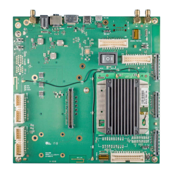
Page 32: On Board Pcb Wlan Antenna
3.8.14 On Board PCB WLAN Antenna The Open-Q 835 carrier board has two on board WLAN PCB antennas that connects to the WiFi / BT on the 835 Processor board via coaxial cables that attaches to MH4L receptacles. These antennas connect to the Processor board in the following configuration:... -
Page 33: On Board Pcb Gps Antenna
3.8.15 On Board PCB GPS Antenna Figure 19 On Board PCB Antennas The Open-Q 835 carrier board has one on-board PCB antennas on the bottom side that connects to the GNSS card via coaxial cable that attaches to MH4L receptacles. The on-board antenna is connected to the GNSS card by default, meanwhile, there are 0ohm jumpers for user to choose to use external GPS antenna via the SMA connector. -
Page 34: Open-Q Display
3.8.18 HDMI Connector J1401 Figure 21 J1401 HDMI Type A Connector The on board HDMI type A connector enables the Open-Q 835 development platform to connect to an external HDMI monitor/ television via an HDMI cable. As part of a new feature, the APQ8098 can now support up to 4K UHD (3840 x 2400 at 60fps) and HDMI 2.0... -
Page 35: Display Connector J1301
Open-Q™ 835 Development Kit based on the Snapdragon™ 835 (APQ8098) Processor User Guide Version 1.0 Please note that the Open-Q 835 Development Kit is for evaluation purposes only and may not be HDMI compliant. 3.8.19 Display Connector J1301 Figure 22 100-Pin Display Connector... - Page 36 LCD that comes preinstalled on the display board. The following figure illustrates the interfacing connectors on the display board. Note: The display board comes as an additional add-on to the Open-Q 835 Development Kit. To purchase this, please visit http://shop.intrinsyc.com...
-
Page 37: Connecting The Display Board To The Development Kit
LCD panel. It is important to note that connector J0501 on the display board needs to connect to J1301 on the carrier board for this configuration to work. Carrier Board Display Card Processor board BLSP/SSC Figure 24 Display Board Default Configuration Copyright Intrinsyc Technologies Corporation... -
Page 38: Camera Connectors
• No of Lanes: 2 x 4 lane MIPI DSI interface via Display Board. • Diagonal Length: 5.5” Note: The display above when mounted on the Intrinsyc Open-Q 835 Display Adapter is meant to work with the carrier board. Altering the use of this LCD panel is not recommended. - Page 39 FLASH_STROBE_ TRIG Output. Connected to APQ8098 FLASH_STROBE FLASH_STROBE (APQ_GPIO22) GPIO22. Default use is for _TRIG (APQ_GPIO22) _TRIG (APQ_GPIO22) camera flash strobe trigger Ground Input. MIPI CSI0 / CSI1 / CSI2 MIPI_CSI0_LANE MIPI_CSI1_LANE MIPI_CSI2_LANE0 data lane 0 Copyright Intrinsyc Technologies Corporation...
- Page 40 MB_VREG_5P0 Power output. 5V Power supply. Maximum 700mA Note: A connection from the camera connectors on the carrier board to the Intrinsyc camera adapter board is established by a 41-pin cable assembly from JAE Electronics (part number JF08R0R041020MA) The following table shows the combinations of camera usage for different use cases...
-
Page 41: Usb 3.1 Typec Connector J1101
Figure 26 J1101 USB3.1 TYPE-C The on board Type-C connector J1101 supports USB 3.1 Gen1, which also supports Type-C with DisplayPort V1.3 3.8.23 GNSS Card Table 3.8-18 Open-Q 835 GNSS Card Mechanical Properties 32.36cm (58.3mm x 55.5mm) Dimensions two 240-pin high speed board-to-board connector... - Page 42 The following are the operating frequencies for WTR5975 GPS: 1574.42 MHz – 1576.42 MHz GLONASS: 1598 MHz to 1606 MHz COMPASS: 1559.05 to 1563.14MHz Galilei: 4.092MHz BW (centered on 1575.42MHz) Figure 27 Open-Q 835 GNSS Card Copyright Intrinsyc Technologies Corporation...
Need help?
Do you have a question about the Open-Q 835 and is the answer not in the manual?
Questions and answers