
Related Manuals for Intrinsyc LANTRONIX Open-Q 624A


Summary of Contents for Intrinsyc LANTRONIX Open-Q 624A
- Page 1 Open-Q™ 624A Development Kit User Guide Part Number PMD-00065 Revision A August 2020...
- Page 2 Lantronix is a trademark of Lantronix, Inc., registered in the United States and other countries. Intrinsyc is a trademark of Intrinsyc Technologies Corporation, registered in Canada and other countries.
- Page 3 Added commands to configure display output • Updated photos • August 2020 Initial Lantronix document. Added Lantronix document part number, Lantronix logo, branding, contact information, and links. For the latest revision of this product document, please go to: http://tech.intrinsyc.com. Open-Q™ 624A Development Kit User Kit...
-
Page 4: Table Of Contents
Contents 1 Introduction Purpose ___________________________________________________________ 6 Scope _____________________________________________________________ 6 Intended Audience ___________________________________________________ 6 2 Documents Applicable Documents ________________________________________________ 7 Reference Documents ________________________________________________ 7 Terms and Acronyms _________________________________________________ 7 List of Figures _______________________________________________________ 9 List of Tables _______________________________________________________ 9 3 Open-Q™ 624A Development Kit Introduction _______________________________________________________ 11 Development Platform Notice __________________________________________ 11 Anti-Static Handling Procedures _______________________________________ 11... - Page 5 3.8.14 Stereo Speaker Header J2100 _____________________________________ 34 3.8.15 External Codec/GPIO Expansion Header J1 __________________________ 36 3.8.16 On Board Digital Mics ___________________________________________ 38 3.8.17 On Board PCB Wi-Fi and BT Antennas ______________________________ 39 3.8.18 GNSS Front-end and Antennas ____________________________________ 40 3.8.19 Display Connector J2 ____________________________________________ 42 3.8.20 Camera connectors J4 and J5 _____________________________________ 45...
-
Page 6: Introduction
This document will cover the following items on the Open-Q 624A: • Block Diagram and Overview • Hardware Features • Configuration • • Carrier Board • Accessories 1.3 Intended Audience This document is intended for users of the Lantronix Open-Q 624A Development Kit. Open-Q™ 624A Development Kit User Kit... -
Page 7: Documents
This section lists the supplementary documents for the Open-Q 624A development kit. 2.1 Applicable Documents Reference Title Intrinsyc Purchase and Software License Agreement for the Open-Q Development 2.2 Reference Documents Documents available on the Lantronix support portal for registered customers. Reference Title Open-Q™... - Page 8 Documents Term and acronyms Definition FWVGA Full Wide Video Graphics Array Global Positioning system HDMI High Definition Media Interface HSIC High Speed Inter Connect Bus JTAG Joint Test Action Group Low Noise Amplifier MIPI Mobile Industry processor interface Multi-Purpose Pin Near Field Communication Radio Frequency SATA...
-
Page 9: List Of Figures
Documents 2.4 List of Figures Figure 1 Assembled Open-Q 624A Development Kit ................12 Figure 2: Development Kit label location ....................13 Figure 3 Open-Q 624A Platform Block Diagram .................. 14 Figure 4 Open-Q 624A SOM ........................ 15 Figure 5 J21 12V DC Power Jack ......................20 Figure 6 SOM Power Source Switch S300 .................. - Page 10 Documents Table 3-9 Serial Debug Port Settings ....................28 Table 3-10 Sensor Expansion Header J53 Pin out ................30 Table 3-11 Audio Expansion Header J50 Pin out ................32 Table 3-12 Stereo Speaker Header J2100 ................... 35 Table 3-13 External Codec/GPIO Expansion Header J1 Pin out ............36 Table 3-14 GNSS Antenna Selection Switch ..................
-
Page 11: Open-Q™ 624A Development Kit
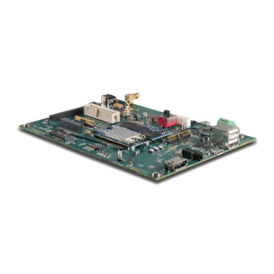
Open-Q™ 624A Development Kit 3 Open-Q™ 624A Development Kit 3.1 Introduction The Open-Q 624A Development Kit provides an evaluation platform for the Qualcomm 624 processor and the Open-Q 624A SOM. This kit is suited for Android / Linux application developers, OEMs, consumer manufacturers, hardware component vendors, to evaluate, optimize, test and deploy applications that can utilize the Qualcomm 624 chipset. - Page 12 Open-Q™ 624A Development Kit LCD / Touchscreen (Optional accessory) • Camera module and adaptor board (Optional accessory) • Quick Start Guide • Figure 1 Assembled Open-Q 624A Development Kit 1. WLAN Antenna 1 (PCB Trace) 19. Speaker Connector 2. Configuration DIP switches 20.
-
Page 13: Getting Started
3.5.1 Registration To register the development kit and gain access to the Lantronix support site, please visit: https://tech.intrinsyc.com/account/register. To proceed with registration, the development kit serial number is required. The serial number can be found on the label on the top side of the SOM. The label contains the Serial Number and WIFI MAC address. -
Page 14: Development Kit Block Diagram
Open-Q™ 624A Development Kit 3.6 Development Kit Block Diagram The block diagram below shows the complete Open-Q 624A development platform, including the SOM and carrier board. Switches Open-Q™ 624A SOM GNSS Ant Conn & LEDs Power & U.FL eMMC LPDDR3 Batt Chg flash Circuits... -
Page 15: Open-Q 624A Som
Open-Q™ 624A Development Kit 3.7 Open-Q 624A SOM The Open-Q 624A SOM measures 50mm x 46.5mm and is connected to the carrier board via three 100-pin SOM to carrier board connectors (B2B Connectors). It provides the basic common set of features with minimal integration efforts for end users to design into a product. -
Page 16: Hardware Features
Open-Q™ 624A Development Kit 3.7.1 Hardware Features The Open-Q™ 624A SOM platform includes the following key features: Table 3-1 Open-Q 624A SOM Features Feature Specification Processor Qualcomm® 624 (APQ8053-Lite) built on 14nm technology Octa-Core 64-bit ARM Cortex A53 1.8GHz Qualcomm Adreno™ 506 GPU OpenGL ES 3.1, OpenCL 2.0 Full, DirectX 12, GPU Tessellation, Geometry Shading Qualcomm Hexagon™... -
Page 17: Som Rf Interfaces For Wi-Fi And Bluetooth Antennas
Open-Q™ 624A Development Kit 3.7.2 SOM RF Interfaces for Wi-Fi and Bluetooth Antennas The Wi-Fi/BT module on the SOM includes the following RF antenna interfaces: ANT0: Wi-Fi antenna 1 • ANT1: Wi-Fi antenna 2 • ANT2: Bluetooth antenna • Wi-Fi antennas: The ANT0 port is for one of the two Wi-Fi antennas and ANT1 is for the other Wi-Fi antenna. Since the Wi-Fi module uses 2x2 MIMO technology and operates in both the 2.4GHz and 5GHz bands, two dual-band antennas are required to be connected to achieve the full performance of the Wi-Fi interface. -
Page 18: Open-Q™ 624A Carrier Board
Open-Q™ 624A Development Kit 3.8 Open-Q™ 624A Carrier Board The Open-Q 624A Carrier board measures 17cm x 11.5cm (195.5cm ), and has various connectors used for connecting different peripherals. Table 3-2 Open-Q 624A Carrier Board Features Feature Specification LCD/Touchscreen 1x 4-lane MIPI DSI connector for optional LCD/touchscreen interface LCD up to 1080p full HD 60fps Camera... -
Page 19: Open-Q™ 624A Carrier Board Expansion Connectors
Open-Q™ 624A Development Kit 3.8.1 Open-Q™ 624A Carrier Board Expansion Connectors The following sections will provide in depth information on each expansion header and connector on the carrier board. The information listed below is of particular use for those who want to interface other external hardware devices with the Open-Q™... -
Page 20: Power Input
Open-Q™ 624A Development Kit 3.8.3 Power Input The Open-Q™ development kit power source connects to the 12V DC power supply jack J21. Current Rating for this port is 3A. Starting from the power jack, the 12V power supply branches off into different voltage rails via step down converters on the carrier board and PMIC on the SOM. -
Page 21: Som Power Source Switch S300
Open-Q™ 624A Development Kit 3.8.4 SOM Power Source Switch S300 Figure 6 SOM Power Source Switch S300 The S300 switch allows the SOM to be powered from either a battery, or an onboard DC switching power supply (U400). In the ‘UP’ position (as shown in the image above) the DC Power supply is the SOM Power source. In this state, BAT_THERM and BATT_ID must be simulated. -
Page 22: Battery Connector J300
Open-Q™ 624A Development Kit Switch Function Description Notes Position CBL_PWR_N When switch is ON, platform will automatically Default out of the box configuration is ON boot when power is applied No Function BAT_THERM Turn switch ON to simulate battery thermistor, Default out of the box configuration is ON. - Page 23 Open-Q™ 624A Development Kit Table 3-5 Battery Connector Pinout J300 Function Pin # Description Notes VBATT_CONN J300[6, 5] Battery Voltage Voltage must be 3.7V ~ 4.2V Battery Identification Used for identification of battery pack J300[4] type. Typically connects to a pull-down BATT_ID_CONN resistor in battery pack.
-
Page 24: Power Probe Header J86
Open-Q™ 624A Development Kit 3.8.7 Power Probe Header J86 Figure 9 J86 Power Probe Header The power probe header is used to sense/monitor the current on the 3.9V power rail going into the SOM (SOM_SYS_PWR). The table below summarizes the pin outs of header J86. A 0.005 Ohm sense resistor is connected between Pins 1 and 2. - Page 25 Open-Q™ 624A Development Kit Can be used as a general power header if user would like to use voltage rails brought out by • connector Table 3-7. Power Header J60 Pin-out Signal Description Pin # Signal Description Pin # MB_ELDO_CAM0_DVDD 1.1V power rail for J60[1] VREG_L17_2P85...
-
Page 26: External Battery Charging Header J26
Open-Q™ 624A Development Kit 3.8.9 External Battery Charging Header J26 Figure 11 External Battery Charging Header J26 External battery charging header J26 breaks out signals to allow for charging of various types of external batteries. Open-Q™ 624A Development Kit User Kit... - Page 27 Open-Q™ 624A Development Kit Table 3-8. Power Header J26 Pin-out Signal Description Pin # Signal Description Pin # J26[1] J26[2] LDO to supply fuel gauge circuits. Connect to bypass BATT_P Battery plus (+) terminal sense J26[3] PMI_VDD_CAP J26[4] capacitor only, Do Not Load.
-
Page 28: Debug Serial Uart Over Usb J22
Open-Q™ 624A Development Kit 3.8.10 Debug Serial UART over USB J22 Figure 12 J22 Debug UART over USB The UART connection used on the Open-Q 624A is a USB micro B connector (J22). This debug UART is available over USB via the FTDI FT232RQ chip on the carrier board. To get the serial terminal working with a PC, user needs to ensure that the appropriate FTDI drivers are installed. -
Page 29: Sensor Io Expansion Header J53
Open-Q™ 624A Development Kit 3.8.11 Sensor IO Expansion Header J53 Figure 13 J53 Sensor Expansion Header The sensor expansion header J53 allows for a 24-pin connection to an optional sensor board (ST Micro STEVAL-MKI128V6 sensor board). If user application does not require a sensor, then this header can be used for other applications that require UART/ SPI/ I2C/ UIM or GPIO input and output connections. - Page 30 Open-Q™ 624A Development Kit Following is the pin breakout for sensor expansion header J53: Table 3-10 Sensor Expansion Header J53 Pin out Description Signal Pin # Description Signal Pin # Sensor I2C Bus – GPIO_6_BLSPx_I2C_SDA J53[1] Accelerometer SENSOR_ACCEL_INT J53[2] SDA (GPIO 6) interrupt input to processor via GPIO42...
- Page 31 Open-Q™ 624A Development Kit Description Signal Pin # Description Signal Pin # Sensor SPI Bus – SSC_SPI_1_CS_N J53[19] Sensor SPI Bus BLSP6_3_SPI_MOSI J53[20] Chip Select (GPIO48) – MOSI (GPIO20) Sensor SPI Bus – SSC_SPI_1_CLK J53[21] Sensor SPI Bus BLSP6_2_SPI_MISO J53[22] CLK (GPIO23) –...
-
Page 32: Audio Input Expansion Header J50
Open-Q™ 624A Development Kit 3.8.12 Audio Input Expansion Header J50 Figure 14 Audio Input Expansion Header J50 This 40-pin expansion header provides the following audio inputs/outputs: 4 digital mic channels (supports 8 mics) • 4 analog mics • Voltage rails to support analog and digital mics •... - Page 33 Open-Q™ 624A Development Kit Description Signal Description Signal Analog MIC1 positive CDC_MIC1_P J50[1] J50[2] differential input Analog MIC1 negative CDC_MIC1_N J50[3] Connects to SOM DMIC 624_DMIC0_CLK J50[4] differential input CLK Input (GPIO 89) Analog MIC2 positive CDC_MIC2_P J50[5] Connects to SOM DMIC 624_DMIC0_DATA J50[6] differential input...
-
Page 34: Mm Headphone And Microphone Jack J27
Open-Q™ 624A Development Kit Description Signal Description Signal 3.3V output power supply MB_VREG_3P3 J50[33 GPIO 117 GPIO_XX_MIC_SEL J50[34] 5.0V output power supply MB_VREG_5P0 J50[35 Analog audio line out 3, CDC_LINE_OUT_3 J50[36] single ended output No Net J50[37 Audio line outputs 3 and 4 CDC_LINE_OUT_R J50[38] GND reference... - Page 35 Open-Q™ 624A Development Kit Figure 16 Stereo Speaker Header J2100 Output from two WSA8815 amplifiers are available at J2100. The WSA8815 amplifiers can deliver up to 4.0 W into an 8 Ω load with 1% THD. Speaker impedances of 4 Ω to 8 Ω are supported. Table 3-12 Stereo Speaker Header J2100 Description Signal...
-
Page 36: External Codec/Gpio Expansion Header J1
Open-Q™ 624A Development Kit 3.8.15 External Codec/GPIO Expansion Header J1 Figure 17 External Codec/GPIO Expansion Header J1 This header exposes GPIO and other signals not exposed or used elsewhere in the platform. It also supports the use of an external audio codec/amplifier through I2S interfaces, as well as supplying power. Table 3-13 External Codec/GPIO Expansion Header J1 Pin out Description Signal... - Page 37 Open-Q™ 624A Development Kit Description Signal Pin # Description Signal Pin # MI2S Bus 2 – Data bit 1 MI2S_2_D1_HDR J1[21] J1[22] (GPIO 138) Note shared with HDMI Connector. Connected this connector default. Connect HDMI turning DIP SW S2 to ‘ON’...
-
Page 38: On Board Digital Mics
Open-Q™ 624A Development Kit 3.8.16 On Board Digital Mics The Open-Q™ 624A carrier board has 8 on board Digital Microphones, located on the bottom of the board. The microphones are Knowles SPK0415HM4H-B-7 [100Hz ~ 10kHz Digital, PDM Microphone MEMS (Silicon) Omnidirectional (-26dB ±3dB @ 94dB SPL)] *Note, availability of onboard DMICs depends on configuration of DIP Switch S10. -
Page 39: On Board Pcb Wi-Fi And Bt Antennas
Open-Q™ 624A Development Kit 3.8.17 On Board PCB Wi-Fi and BT Antennas The Open-Q™ 624A carrier board has two on-board Wi-Fi PCB antennas and one on-board Bluetooth antenna that connects to the Wi-Fi/BT module on the SOM via coaxial cables. These antennas connect to the SOM in the following configuration: WLAN ANT1 on the carrier board connects through coax connector J9 to MH4F connector ANT0 on the Wi-Fi/BT module... -
Page 40: Gnss Front-End And Antennas
Open-Q™ 624A Development Kit 3.8.18 GNSS Front-end and Antennas The Open-Q™ 624A carrier board includes a GNSS RF front-end circuit as well as a PCB trace antenna and an SMA type external antenna connector. The RF front-end circuit includes an LNA and a SAW filter for improved performance and an antenna switch to enable connection to either the PCB trace antenna or the SMA external antenna connector. - Page 41 Open-Q™ 624A Development Kit Therefore, if the goal is to evaluate the GNSS receiver performance of the SOM with a user-selected antenna intended for an end product, it should be connected directly to the SOM’s GPS antenna connector (U.FL) to eliminate the effects of the LNA, filter, and coax cable losses on the carrier board.
-
Page 42: Display Connector J2
Supports up to two touch screen controllers Supports I2C or SPI via BLSP3 Note: An optional 4.5” LCD/touchscreen accessory is available for the Open-Q 624A development kit. See section 0 below for more information. To purchase this, please visit http://shop.intrinsyc.com or contact Lantronix at sales@lantronix.com for details. - Page 43 Open-Q™ 624A Development Kit Pin # Signal Description J2[1] J2[2] VREG_L5_1P8 Power output. Connected to PM8953 VREG_L5 regulator. Default is +1.8V. Maximum current 600mA (shared with other platform circuitry) J2[3] VREG_L10_3P0 Power output. Connected to PM8953 VREG_L5 regulator. Default is +3.0V.
- Page 44 Open-Q™ 624A Development Kit Pin # Signal Description J2[26] VOUT_WLED_DISP Backlight LED Voltage Output J2[27] WLED_SINK1_DISP Backlight LED String 1 Current Sink. Max 30mA J2[28] J2[29] WLED_SINK2_DISP Backlight LED String 2 Current Sink. Max 30mA J2[30] WLED_SINK3_DISP Backlight LED String 3 Current Sink. Max 30mA J2[31] J2[32] WLED_SINK4_DISP...
-
Page 45: Camera Connectors J4 And J5
Open-Q™ 624A Development Kit 3.8.20 Camera connectors J4 and J5 The Open-Q 624A development kit supports two 4-lane MIPI camera interfaces via three separate JAE 41-pin connectors. The following are some features of the camera connectors: 2 x 4 lane MIPI CSI signals •... - Page 46 Open-Q™ 624A Development Kit Pin # CAM0(J5) CAM1(J4) Description VREG_L22_2P8 MB_ELDO_CAM1_VCM Power output. Connected to PM8953 VREG_L22 regulator (150mA) on CAM0, and VREG_L22_2P8 MB_ELDO_CAM1_VCM onboard LDO (300mA) on CAM1. Default is +2.80. VREG_L6_1P8 VREG_L6_1P8 Power output. Connected to PM8953 VREG_L6_1P8. Default is +1.8V.
- Page 47 Open-Q™ 624A Development Kit Pin # CAM0(J5) CAM1(J4) Description MIPI_CSI0_CLK_N MIPI_CSI1_CLK_N Input. MIPI CSI0 / CSI1 clock lane MIPI_CSI0_CLK_P MIPI_CSI1_CLK_P Input. MIPI CSI0 / CSI1 clock lane Ground MIPI_CSI0_LANE1_N MIPI_CSI1_LANE1_N Input. MIPI CSI0 / CSI1 data lane 1 MIPI_CSI0_LANE1_P MIPI_CSI1_LANE1_P Input.
- Page 48 Open-Q™ 624A Development Kit Pin # CAM0(J5) CAM1(J4) Description MB_VREG_5P0 MB_VREG_5P0- Not connected by Default Note: A connection from the camera connectors on the carrier board to the camera adapter board is established by a 41-pin cable assembly from JAE Electronics (part number JF08R0R041020MA) An optional Camera Module Accessory is available.
-
Page 49: Automation Connector Header J3100
Open-Q™ 624A Development Kit 3.8.21 Automation Connector Header J3100 Figure 24 J3100 Automation connector header This 60-pin header is used for automating tests on the development platform. Such tests include powering on and off and managing automated software downloads on the board. If automation is not required, user can access free GPIO pins from this header. -
Page 50: Buttons
Open-Q™ 624A Development Kit Description Signal Pin # Description Signal Pin # Input. +3.9V System AUTO_VBATT Power for SOM. 3.8.22 Buttons There are 3 push-buttons on the platform, which perform typical Android device behavior. Figure 25 Buttons • S100 – Power Button. Used to boot device, lock/wake device (Note the platform will auto-boot when power is applied when DIP SW S1 position 1 is set to ‘ON’). -
Page 51: Usb Type C Port J2500
Open-Q™ 624A Development Kit 3.8.23 USB Type C Port J2500 Figure 26 USB Type C Port J2500 J2500 is a USB 3.0 Type C Connector with SuperSpeed and High-Speed connections. The connector pinout follows the industry standard for USB 3.0. Embedded Display Port (eDP) is not supported. Android ADB Access is possible on the HS lines using a USB Type C to Micro B adaptor. -
Page 52: Leds
Open-Q™ 624A Development Kit 3.8.24 LEDs LED DS1 is connected to the PMI8952 ‘CHG_LED’ pin and signals charging status. It is configured by default to indicate battery charging status. Figure 27 User LEDs Two user controlled general purpose LED’s are also available: DS2 (BLUE) –... -
Page 53: Hdmi Connector J25
Open-Q™ 624A Development Kit 3.8.25 HDMI Connector J25 Figure 28 HDMI Connector J25 The on-board HDMI type A connector enables the Open-Q 624A development kit to connect to an external HDMI monitor/ television via an HDMI cable. The Open-Q 624A supports up to 1080P 60fps. Note that the HDMI port is for evaluation purposes only and may not be HDMI compliant. -
Page 54: Accessories
Two different camera modules are available as optional accessories and are not included in the development kit. They are available for purchase from the Lantronix online store in the Accessories section: https://shop.intrinsyc.com/ 1. 13MP Camera – based on the Sony IMX214 13MP sensor with a raw RGB MIPI CSI output, it interfaces to the development kit through the included 21cm JAE interface cable at connector. - Page 55 Open-Q™ 624A Development Kit LCD Type: IPS Touch: PCAP touch panel with cover glass No of Lanes: 1 x 2 lane MIPI DSI interface via Display Board. Diagonal Sizes: 4.5” NOTE: The Open-Q 624A Development Kit has an HDMI video output and can be purchased with or without the optional LCD / touch panel.
Need help?
Do you have a question about the LANTRONIX Open-Q 624A and is the answer not in the manual?
Questions and answers