Intrinsyc Lantronix Open-Q 820 User Manual
Development kit for qualcomm apq8096 processor
Hide thumbs
Also See for Lantronix Open-Q 820:
- User manual (57 pages) ,
- User manual (51 pages) ,
- User manual (44 pages)

Related Manuals for Intrinsyc Lantronix Open-Q 820


Summary of Contents for Intrinsyc Lantronix Open-Q 820
- Page 1 Open-Q™ 820 Development Kit for Qualcomm™ APQ8096 Processor User Guide Part Number PMD-00052 Revision A August 2020...
- Page 2 Your use of this document is subject to and governed by those terms and conditions in the Intrinsyc Purchase an Open-Q Development Kit Based on Qualcomm™ APQ8096 Series Processor and Software License Agreement for the Open-Q Development Kit Based on Qualcomm™ APQ8096 Series Processor, which you or the legal entity you represent, as the case may be, accepted and agreed to when purchasing an Open-Q Development Kit from Intrinsyc Technologies Corporation.
- Page 3 Updated WiFi / BT Antenna numbering Updated Table 3.8.21-1 August 2020 Initial Lantronix document. Added Lantronix document part number, Lantronix logo, branding, contact information, and links. For the latest revision of this product document, please go to: http://tech.intrinsyc.com. Open-Q™ 820 Dev Kit User Guide...
-
Page 4: Table Of Contents
Contents 1. Introduction Purpose _____________________________________________________________ 6 Scope ______________________________________________________________ 6 Intended Audience ____________________________________________________ 6 2. Documents Applicable Documents _________________________________________________ 7 Reference Documents _________________________________________________ 7 Terms and Acronyms __________________________________________________ 7 3. Open-Q™ 820 Development Kit Introduction _________________________________________________________ 11 Development Platform Notice ___________________________________________ 11 Anti-Static Handling Procedures _________________________________________ 11 Kit Contents ________________________________________________________ 11 Hardware Identification Label ___________________________________________ 12... - Page 5 3.8.18 Display Connector J2 _____________________________________________ 37 3.8.19 PCI Express 1X Slot J30 __________________________________________ 41 3.8.20 Mini PCI Express Connector J72 ____________________________________ 41 3.8.21 Camera Connectors ______________________________________________ 43 3.8.22 Power Header via 20 Pin Connector J60 ______________________________ 47 3.8.23 Automation Connector Header J59 __________________________________ 49 3.8.24 Ethernet AVB Expansion Header J73 ________________________________ 50 3.8.25...
-
Page 6: Introduction
1. Introduction 1.1 Purpose The purpose of this user guide is to provide primary technical information on the Open-Q™ 820 Development Kit based on the Qualcomm™ APQ8096 Processor For more background information on this development kit, visit: https://www.lantronix.com/products/open-q-820-development-kit/ 1.2 Scope This document will cover the following items on the Open-Q 820: Block Diagram and Overview •... -
Page 7: Documents
This section lists the supplementary documents for the Open-Q 820 development kit. 2.1 Applicable Documents Reference Title Intrinsyc Purchase and Software License Agreement for the Open-Q Development 2.2 Reference Documents Reference Title Hardware Document Set for the Qualcomm APQ8096 based Open-Q... - Page 8 Documents Term and acronyms Definition FWVGA Full Wide Video Graphics Array Global Positioning system HDMI High Definition Media Interface HSIC High Speed Inter Connect Bus JTAG Joint Test Action Group Low Noise Amplifier MIPI Mobile Industry processor interface Multi-Purpose Pin Near Field Communication Radio Frequency SATA...
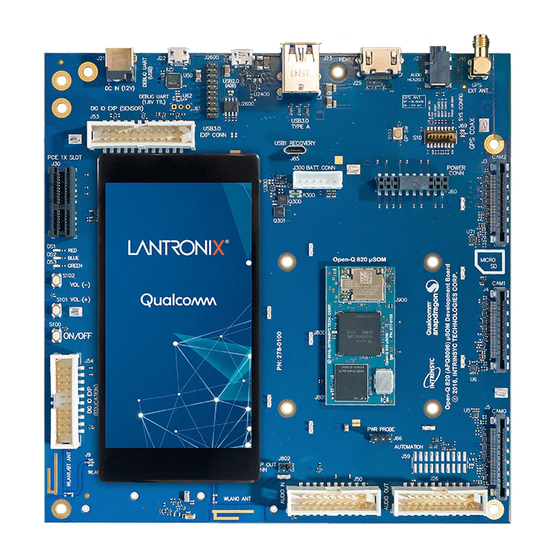
- Page 9 Documents List of Figures Figure 1 Assembled Open-Q 820 Development Kit ______________________________________ 12 Figure 2 Open-Q 820 Block Diagram _________________________________________________ 13 Figure 3 Open-Q 820 SOM ________________________________________________________ 14 Figure 4 SOM Block Diagram _______________________________________________________ 15 Figure 5 J21 12V DC Power Jack ____________________________________________________ 24 Figure 6 J86 Power Probe Header ___________________________________________________ 24 Figure 7 J61 3.3V TTL Debug UART _________________________________________________ 25 Figure 8 J22 Debug UART Over USB _________________________________________________ 26...
- Page 10 Documents Table 3.8.21-2. MIPI CSI Camera Use Cases __________________________________________ 47 Table 3.8.22-1. Power Header J60 Pin-out _____________________________________________ 48 Table 3.8.23-1. General System J59 Pin Out ___________________________________________ 49 Open-Q™ 820 Dev Kit User Guide...
-
Page 11: Open-Q™ 820 Development Kit
Open-Q™ 820 Development Kit 3. Open-Q™ 820 Development Kit 3.1 Introduction The Open-Q 820 provides a quick reference or evaluation platform for Qualcomm’s latest 820 series - Qualcomm APQ8096 processor. This kit is suited for Android / Linux application developers, OEMs, consumer manufacturers, hardware component vendors, video surveillance, robotics, camera vendors, and flash chip vendors to evaluate, optimize, test and deploy applications that can utilize the Qualcomm 820 series technology. -
Page 12: Hardware Identification Label
Serial Number • WIFI MAC address [optional] • Refer to https://tech.intrinsyc.com/projects/serialnumber/wiki for more details about locating the serial number, as this will be needed to register the development kit. To register a development kit, please visit: https://tech.intrinsyc.com/account/register. Mini-ITX form-factor carrier board: •... -
Page 13: System Block Diagram
Open-Q™ 820 Development Kit 3.6 System Block Diagram The Open-Q 820 development platform consists of three major components Open-Q 820 SOM • Carrier board for I/O and connecting with external peripherals • Display Adapter Board (additional accessory) • The following diagram explains the interconnectivity and peripherals on the development kit. LEDs (optional) APQ8096... -
Page 14: Som Mechanical Properties
Open-Q™ 820 Development Kit QCA6174 Atheros Wi-Fi + BT combo chip over PCIe, UART, PCM • 32 GB UFS 2.0. • WGR7640 RF Front End • WCD9335 Audio Codec • 82mm 42mm Figure 3 Open-Q 820 SOM 3.7.1 SOM Mechanical Properties Area 34.44 cm (42 mm x 82 mm) -
Page 15: Hardware Specification
Open-Q™ 820 Development Kit Carrier Board LEDs APQ8096 Power Circuit IQ + SSBI WGR7640 PCIe0 QCA6174 PMi8996 UART WiFi/BT SPMI PM8996 2 lanes 32 to 64GB PCIe1 PCIe 2.1 eMMC 5.1 SDC1 8-bit SDIO 16 to 64GB 4-bit SDIO SDC2 PCIe2 PCIe 2.1 DSI 0... -
Page 16: Table 3.7-1 Open-Q Hardware Features
Open-Q™ 820 Development Kit Table 3.7-1 Open-Q Hardware Features Subsystem / Feature Set Description Specification Connectors Chipset APQ8096 Qualcomm® APQ8096 Qualcomm® Kyro CPU, Processor quad core, 64-bit ARM V8 compliant processor, 2.2GHz PMIC (PM8996 & Qualcomm® PMIC, PMi8996) Companion PMIC for APQ8096 processor Memory 3GB LPDDR4... -
Page 17: Som Rf Specification For Wifi, Bt, Gps
Open-Q™ 820 Development Kit Subsystem / Feature Set Description Specification Connectors 3 x analog MICs Analog MIC input Analog differential input 3 x digital MICs Digital MIC input Digital input Interfaces 3 x MIPI CSI Camera Connectors MIPI Alliance Specification v1.0 CSI0, CSI1, CSI2 2 x USB HS &... - Page 18 Open-Q™ 820 Development Kit Note that two dual-band (2.4GHz + 5GHz) antennas are required to be connected to achieve full performance of the Wi-Fi interface. If only Bluetooth is being used, then only a single 2.4GHz antenna connected to ANT1 is necessary.
-
Page 19: Open-Q™ Carrier Board
Open-Q™ 820 Development Kit 3.8 Open-Q™ Carrier Board The Open-Q 820 Carrier board is a Mini-ITX form factor board with various connectors used for connecting different peripherals. The following are the mechanical properties of the carrier board: Dimensions 289 cm (170mm x 170mm) Form Factor Mini-ITX... -
Page 20: Open-Q™ 820 Carrier Board Expansion Connectors
Open-Q™ 820 Development Kit Function Switch Description Notes Enables WATCHDOG_DISABLE when DIP switch turned on. Controlled by APQ-GPIO WATCHDOG _DISABLE S10-6 Default out of the box configuration is OFF S10-7 Option to select which antenna to use for GPS. When DIP switch ON GPS external antenna is being used (SMA connector). - Page 21 Open-Q™ 820 Development Kit Domain Description Specification Usage Volume – key SMD Button Volume – Key Sensor IO Connector (DNP) 24 pin Sensor Expansion Support any user sensor card, Available via Lantronix Connectors optional accessories kit Standard 44-pin ST Micro PLCC Supports Gen-9 sensor support via optional daughter card connector as stuff option...
- Page 22 Open-Q™ 820 Development Kit Domain Description Specification Usage WLAN Antenna 2X PCB Antenna 2.4 – 5.1 GHz Antenna to SOM WiFi module GPS Antenna PCB Antenna GPS : Antenna to SOM GPS module 1574.42 MHz – 1576.42 MHz GLONASS : 1587 MHz –...
-
Page 23: Open-Q Power Specification
Open-Q™ 820 Development Kit Domain Description Specification Usage supported) PCI Express Slot PCI Express for external PCIe1 v2.1 To connect an Ethernet PCIe peripheral connectivity card board to support Ethernet. Supports half card only Supports 10W card via power supply Supports 25W card via ATX power supply Mini PCI Express Connector... -
Page 24: Power Probe Header J86
Open-Q™ 820 Development Kit Figure 5 J21 12V DC Power Jack The SOM consists of 2 PMIC modules. Functionalities of the 2 modules are outlined below. PMI8996 PMIC is used for: • Source various regulated power rails • Support for battery charging on the PMI8996 is not implemented on the platform. The carrier board uses a 3.8V constant power input to the SOM. -
Page 25: Debug Serial Uart Header J61
Open-Q™ 820 Development Kit Table 3.8-3 Power Header J86 Pin-out Description Signal SOM power positive current sense SOM_PWR_SENSE_P J86[1] line SOM power negative current sense SOM_PWR_SENSE_N J86[2] line J86[3] 3.8.5 Debug Serial UART Header J61 Figure 7 J61 3.3V TTL Debug UART The UART header and supporting circuitry does not come preinstalled. -
Page 26: Debug Serial Uart Over Usb J22
Open-Q™ 820 Development Kit 3.8.6 Debug Serial UART Over USB J22 Figure 8 J22 Debug UART Over USB The UART connection used on the Open-Q 820 is a USB micro B connector (J22). This debug UART is available over USB via the FTDI FT232RQ chip on the carrier board. To get the serial terminal working with a PC, user needs to ensure that the appropriate FTDI drivers are installed. -
Page 27: Sensor Io Expansion Header J53
Open-Q™ 820 Development Kit Note: Lantronix does not provide software support for JTAG Table 3.8-5 JTAG Header J51 Pin out Description Signal Description Signal J51[2] JTAG Power detect JTAG_PWR J51[1] J51[4] Target RESET_N signal TRST_N J51[3] J51[6] TDI Signal (Target DATA IN) J51[5] J51[8] TMS Signal... -
Page 28: Table 3.8-6 Sensor Expansion Header J53 Pin Out
Open-Q™ 820 Development Kit Following is the pin breakout for sensor expansion header J53. Table 3.8-6 Sensor Expansion Header J53 Pin out Description Signal Description Signal SSC I2C-3 serial data SSC_I2C_3_SDA J53[1] Accelerometer interrupt ACCEL_INT_N J53[2] input to processor via GPIO117 SSC I2C-3 serial clock SSC_I2C_3_SCL... -
Page 29: Nfc Expansion Header J52 (Exp1)
The NFC expansion header provides a 20 pin connector for attaching an optional NFC board (please contact Lantronix for availability of the NFC board at sales@lantronix.com or visit http://shop.intrinsyc.com). This header also allows user to connect to the free GPIOs and I2C lines when NFC is not used; therefore, enabling Open-Q™ 820 Dev Kit User Guide... -
Page 30: Table 3.8-7 Nfc Expansion Header J52 Pin Out
Open-Q™ 820 Development Kit other use cases. Please refer to Table 3.8-7 for detailed information regarding the signals that are being brought out by this connector. Note that this NFC expansion header is also compatible with the APQ8074 DragonBoard but the extra last four pins should not be connected. -
Page 31: Education / Gpio Header J54 (Exp2)
Open-Q™ 820 Development Kit 3.8.10 Education / GPIO header J54 (EXP2) Figure 13 J54 Education / GPIO Header Education/ GPIO header expansion J54 is a 20 pin connector that provides access to BLSP1 signals with level shifters. It is ideally used for connecting external peripherals such as microcontrollers and any other devices that are based on I2C, SPI, UART, UIM and GPIO. -
Page 32: Anc Headset Jack J27
Open-Q™ 820 Development Kit Description Signal Description Signal BLSP1_2_3P3(3.3V) BLSP1_SPI_MIS J54[5] PM8996 MPP GPIO2 PM_MPP02 J54[6] O (APQ-GPIO1) BLSP1_1_3P3(3.3V) BLSP1_SPI_CS J54[7] PM8996 MPP GPIO4 PM_MPP04 J54[8] _N (APQ- GPIO2) BLSP1_0_3P3(3.3V) BLSP1_SPI_CL J54[9] PM8996 MPP GIPO1 PM_MPP01 J54[10 K (APQ-GPIO3) APQ-GPIO124 level shifted EXP_IRQ_3P3 J54[11 PM8996 MPP GIPO6... -
Page 33: Audio Inputs Expansion Header J50
Open-Q™ 820 Development Kit 3.8.12 Audio Inputs Expansion Header J50 Figure 15 J50 Audio Inputs Expansion Header This header expansion provides the following audio inputs: 1. 3 digital mics 2. 3 analog mics 3. Voltage rails to support analog and digital mics For details on how to connect analog or digital microphones to system, refer to sections 4.13.1 and 4.13.2 on Open-Q™_820DevKit_SOM_TechNote13 (document R-3). -
Page 34: Audio Outputs Expansion Header J26
Open-Q™ 820 Development Kit Description Signal Description Signal Clock for digital MIC 1 and CDC_DMIC_CLK0 J50[13 Clock for digital MIC 3 and CDC_DMIC_CLK1 J50[14] Digital MIC 1 and 2 data CDC_DMIC_DATA0 J50[15 Digital MIC 3 and 4 data CDC_DMIC_DATA J50[16] line line 1.8V power supply max... -
Page 35: On Board Pcb Wlan Antennas
Open-Q™ 820 Development Kit Table 3.8-10 Audio Outputs Expansion Header J26 Pin out Description Signal Description Signal Analog audio line out 1, CDC_LINE_OUT1_ J26[1] Analog audio line out 1, CDC_LINE_OUT1_ J26[2] positive differential output negative differential output Analog audio line out 2, CDC_LINE_OUT2_ J26[3] Analog audio line out 2,... -
Page 36: External And On Board Pcb Gps Antenna
Open-Q™ 820 Development Kit ANT1 ANT2 Figure 17 On Board PCB Antennas 3.8.15 External and on Board PCB GPS Antenna The Open-Q™ 820 carrier board allows user the flexibility of using an external (via SMA connector) or an on board PCB GPS antenna. Depending on which antenna is used, dip switch S10 needs to be configured (see table below for details). -
Page 37: Hdmi Connector J25
Open-Q™ 820 Development Kit Display 3840 x 2400 at 60fps, 2560 buffer width (10 layers blending) HDMI V2.0 (4K60) 3.8.17 HDMI Connector J25 The on board HDMI type A connector enables the Open-Q development platform to connect to an external HDMI monitor/ television via an HDMI cable. - Page 38 LCD panel, while J7 allows users to access the display signals on the carrier board (display connector J2) via connector J8 on the display board. Note: The display board comes as an additional add-on to the Open-Q 820 development kit. To purchase this, please visit http://shop.intrinsyc.com or contact Lantronix at sales@lantronix.com for details.
-
Page 39: Figure 18 Display Board Block Diagram
Open-Q™ 820 Development Kit JAE51-pin Connector FWVGA Truly LCD Display ERM8 ERM8 Display Adaptor Board Figure 18 Display Board Block Diagram 3.8.18.1 Connecting the Display Board to the Development Kit This configuration allows the user to use the preinstalled LCD display that comes with the display adaptor board. -
Page 40: Figure 19 Display Board Default Configuration
Open-Q™ 820 Development Kit Carrier Board JAE51-pin Display Adaptor Connector Board ERF8 FWVGA Truly LCD Display DSI0 DSI0 DSI1 DSI1 Via MXM Connector ERM8 ERM8 DSI0 Figure 19 Display Board Default Configuration 3.8.18.2 Display Panel This LCD panel comes preinstalled on the Open-Q 820 display adaptor board (part number: 225-0100). Below are the Panel specifications: Resolution: 480x854 •... -
Page 41: Pci Express 1X Slot J30
Open-Q™ 820 Development Kit 3.8.19 PCI Express 1X Slot J30 The PCI Express slot (J30) used on the Open-Q 820 development kit is a standard PC style half-height card slot. It allows for external peripheral connectivity such as Gigabit Ethernet, Gigabit Wi-Fi, or PCIe based audio / video processors. -
Page 42: Figure 21 J72 Mini Pcie Connector
Open-Q™ 820 Development Kit Figure 21 J72 Mini PCIe Connector Mounting holes for half size card Mounting holes for full size card Figure 22 J72 Mounting Holes for Mini PCIe Connector Open-Q™ 820 Dev Kit User Guide... -
Page 43: Camera Connectors
Open-Q™ 820 Development Kit 3.8.21 Camera Connectors The Open-Q 820 development kit supports three 4-lane MIPI camera interfaces via three separate JAE 41-pin connectors. The following are some features of the camera connectors: 3 x 4 lane MIPI CSI signals •... - Page 44 Open-Q™ 820 Development Kit Pin# CAM0(J5) CAM1(J4) CAM2(J3) Description 9,10 VREG_LVS1A_1P8 VREG_LVS1A_1P8 VREG_LVS1A_1P8 Power output. Connected to PM8996 VREG_LVS1A switch output. Default is +1.8V. Maximum current 300mA Ground FLASH_STROBE_EN FLASH_STROBE_EN FLASH_STROBE_EN Output. Connected to APQ8096. (APQ_GPIO21) (APQ_GPIO21) (APQ_GPIO21) Default use is for camera flash strobe enable CAM0_RST_N CAM1_RST_N...
- Page 45 Open-Q™ 820 Development Kit Pin# CAM0(J5) CAM1(J4) CAM2(J3) Description MIPI_CSI0_LANE1_N MIPI_CSI1_LANE1_N MIPI_CSI2_LANE1_N Input. MIPI CSI0 / CSI1 / CSI2 data lane 1 MIPI_CSI0_LANE1_P MIPI_CSI1_LANE1_P MIPI_CSI2_LANE1_P Input. MIPI CSI0 / CSI1 / CSI2 data lane 1 Ground MIPI_CSI0_LANE2_N MIPI_CSI1_LANE2_N MIPI_CSI2_LANE2_N Input. MIPI CSI0 / CSI1 / CSI2 data lane 2 MIPI_CSI0_LANE2_P MIPI_CSI1_LANE2_P...
- Page 46 Open-Q™ 820 Development Kit Note: A connection from the camera connectors on the carrier board to the camera adapter board is established by a 41-pin cable assembly from JAE Electronics (part number JF08R0R041020MA) The table below shows the combinations of camera usage for different use cases Open-Q™...
-
Page 47: Power Header Via 20 Pin Connector J60
Open-Q™ 820 Development Kit Table 3.8.21-2. MIPI CSI Camera Use Cases CSI PHY Use case Comment CSI0 Up to 4 lane One Camera of 4 lane or One camera of 3 lane One Camera of 2 lane One Camera of 1 lane CSI 1 Up to 4 lane One Camera of 4 lane or... - Page 48 Open-Q™ 820 Development Kit Table 3.8.22-1. Power Header J60 Pin-out Descriptio Signal Pin NO Descriptio Signal Pin NO 1.05V power MB_ELDO_CAM0_DVDD J60[1] 2.85V power VREG_L17A_2P8 J60[2] rail for camera rail for camera 0 (AVDD) 2.8V power rail VREG_L23A_2P8 J60[3] J60[4] for camera 0, 2 (VDD) J60[5]...
-
Page 49: Automation Connector Header J59
Open-Q™ 820 Development Kit 3.8.23 Automation Connector Header J59 Figure 25 J59 Automation Connector Header This header is used for automating tests on the development platform. Such tests include powering on and off and managing automated software downloads on the board. If automation is not required, user can access free GPIO pins from this header. -
Page 50: Ethernet Avb Expansion Header J73
Open-Q™ 820 Development Kit Description Signal Description Signal USB boot FORCED_USB_BOO J26[11 VBUS enable. USB_VBUS_DIS_N J26[12 Activating ESD protection circuit when asserted low J26[13 J26[14 J26[15 Chip reset input APQ_RESOUT_N J26[16 J26[17 J26[18 J26[19 J26[20 3.8.24 Ethernet AVB Expansion Header J73 Figure 25 J73 Ethernet AVB Expansion Header This header is used for interfacing with automotive peripherals via Ethernet AVB standard.
Need help?
Do you have a question about the Lantronix Open-Q 820 and is the answer not in the manual?
Questions and answers