Table of Contents
Advertisement
Quick Links
Open-Q™ 660 µSOM Development Kit
User Guide
[Document: ITC-01RND1336-UG-001 Version: 1.0]
Your use of this document is subject to and governed by those terms and conditions in the Intrinsyc Purchase an Open-Q Development Kit Based on
Snapdragon 600 Series (SDA660) Processor and Software License Agreement for the Open-Q 660 Development Kit, which you or the legal entity you
represent, as the case may be, accepted and agreed to when purchasing an Open-Q Development Kit from Intrinsyc Technologies Corporation
("Agreement"). You may use this document, which shall be considered part of the defined term "Documentation" for purposes of the Agreement, solely
in support of your permitted use of the Open-Q 660 Development Kit under the Agreement. Distribution of this document is strictly prohibited without
the express written permission of Intrinsyc Technologies Corporation and its respective licensors, which they can withhold, condition or delay in its sole
discretion.
Intrinsyc is a trademark of Intrinsyc Technologies Corporation., registered in Canada and other countries.
Qualcomm and Snapdragon are trademarks of Qualcomm Incorporated, registered in the United States and other countries. Other product and brand
names used herein may be trademarks or registered trademarks of their respective owners.
This document contains technical data that may be subject to U.S. and international export, re-export, or transfer ("export") laws. Diversion contrary to
U.S. and international law is strictly prohibited.
Advertisement
Table of Contents

Related Manuals for Intrinsyc Open-Q 660 mSOM


Summary of Contents for Intrinsyc Open-Q 660 mSOM
- Page 1 [Document: ITC-01RND1336-UG-001 Version: 1.0] Your use of this document is subject to and governed by those terms and conditions in the Intrinsyc Purchase an Open-Q Development Kit Based on Snapdragon 600 Series (SDA660) Processor and Software License Agreement for the Open-Q 660 Development Kit, which you or the legal entity you represent, as the case may be, accepted and agreed to when purchasing an Open-Q Development Kit from Intrinsyc Technologies Corporation (“Agreement”).
- Page 2 Open-Q™ 660 µSOM Development Kit User Guide Version 1.0 IDENTIFICATION Document Title Open-Q™ 660 µSOM Development Kit User Guide Document Number ITC-01RND1336-UG-001 Version Date Apr. 30, 2019 History REVISION DATE DESCRIPTION PAGES April 30, 2019 Initial Draft © Copyright Intrinsyc Technologies Corporation 2 of 39...
-
Page 3: Table Of Contents
Audio IO Expansion Headers 1 and 2, J2000 (9) and J2001 (7) ......34 3.7.20 Audio Headset Jack J1800 (8) ................. 36 3.7.21 WLAN / BT Antenna Connections ................37 3.7.22 Quiet Thermistor RT800 (35) .................. 39 © Copyright Intrinsyc Technologies Corporation 3 of 39... - Page 4 Table 3 - System Configuration DIP Switch Settings ................18 Table 4. Battery Connector J300 Pinout ....................20 Table 5 - Power Header J301 Pinout....................21 Table 6. Power Header J700 (36) ......................22 © Copyright Intrinsyc Technologies Corporation 4 of 39...
- Page 5 Table 12. Audio Inputs Expansion Header Pinout J1900 (33) ............32 Table 13. Audio Outputs Expansion Header Pinout J1901..............33 Table 14. Audio IO Expansion Header #1 J2000 Pinout ..............35 Table 15. Audio IO Expansion Header #2 J2001 Pinout ..............36 © Copyright Intrinsyc Technologies Corporation 5 of 39...
-
Page 6: Introduction
1.1 Purpose The purpose of this user guide is to provide instructions and technical information on the Open-Q 660 µSOM Development Kit. You can find information on this and other Intrinsyc development kits on the Intrinsyc web site: https://www.intrinsyc.com/development-kits/ 1.2 Scope This document will cover the following items on the Open-Q 660 µSOM Development Kit:... -
Page 7: Documents
2.1 Applicable Documents REFERENCE TITLE Intrinsyc Purchase and Software License Agreement for the Open-Q Development 2.2 Reference Documents The below listed documents are available on the Intrinsyc Technical Portal: https://tech.intrinsyc.com (dev kit registration required). REFERENCE TITLE Open-Q 660 µSOM HW Device Specification Open-Q 660 µSOM –... - Page 8 PMIC / Companion chip and baseband processor protocol) UART Universal Asynchronous Receiver Transmitter Universal Flash Storage User Identity module Universal Serial Bus USB HS USB High Speed USB SS USB Super Speed © Copyright Intrinsyc Technologies Corporation 8 of 39...
-
Page 9: Open-Q 660 Μsom Development Kit
The Open-Q 660 µSOM Development Kit comes with Android software pre-programmed and includes the following: o Open-Q 660 µSOM with the Snapdragon 660 (SDA660) processor o Mini-ITX form-factor carrier board o AC power adapter © Copyright Intrinsyc Technologies Corporation 9 of 39... -
Page 10: Important Locations
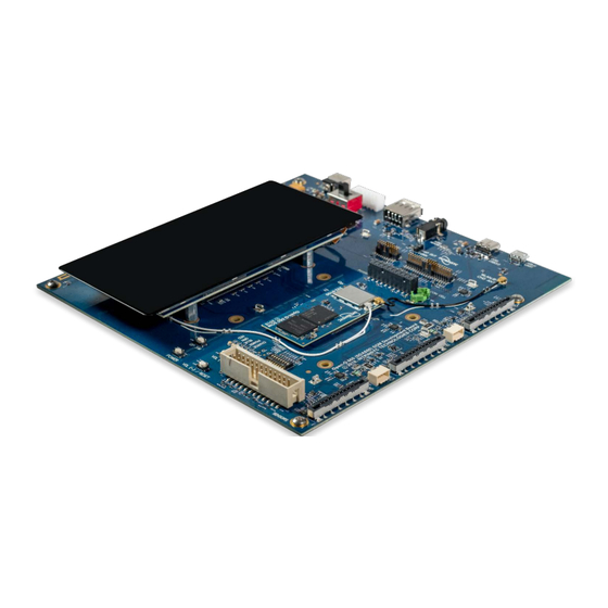
Open-Q™ 660 µSOM Development Kit User Guide Version 1.0 3.4.1 Important Locations The diagram below shows the locations of key components, interfaces, and controls. Figure 1. Assembled Open-Q 660 µSOM Development Kit © Copyright Intrinsyc Technologies Corporation 10 of 39... -
Page 11: Table 1. List Of Development Kit Features Itemized In The Figure Above
Open-Q LCD Panel Digital IO Expansion Header J2200 Audio Outputs Expansion J1901 Audio Inputs Expansion J1900 Micro SD card socket J1500 On-Board Quiet Thermistor RT800 Power Header J700 Coin Cell Holder B300 © Copyright Intrinsyc Technologies Corporation 11 of 39... -
Page 12: Block Diagram
Sensor Header UART / SPI / I C / GPIO UART FTDI Debug UART UART Serial USB microUSB Open-Q 660 µSOM Development Board Figure 2. Open-Q 660 µSOM Dev Kit Block Diagram © Copyright Intrinsyc Technologies Corporation 12 of 39... -
Page 13: Optional Accessories
3.4.3 Optional Accessories Optional accessories are available for the Open-Q 660 µSOM Development Kit, like LCD Panel, Camera adapter, and sensor board. Please visit the Intrinsyc product store for availability of these accessories: https://shop.intrinsyc.com/collections/all, or contact sales@intrinsyc.com. © Copyright Intrinsyc Technologies Corporation... -
Page 14: Getting Started
This section explains how to setup the Open-Q 660 µSOM Development Kit and start using it. 3.5.1 Registration To register the development kit and gain access to the Intrinsyc Technical Document Portal, please visit: http://tech.intrinsyc.com/account/register. To proceed with registration, the development kit serial number is required. These serial numbers can be found on the labels that are present on the SOM and carrier boards. -
Page 15: Open-Q 660 Μsom
Hirose DF40 connectors which allows essential power rails and signals to be exposed for supporting other peripherals and interfaces on the platform. For detailed information about the Open-Q 660 µSOM, see the device specification noted as reference document R-1. © Copyright Intrinsyc Technologies Corporation 15 of 39... -
Page 16: Open-Q 660 Carrier Board
USB 2.0 Host interface WLAN Antennas 13, 14 2 PCB Antennas Coax connection to SOM WiFi module Coin Cell Holder Coin Cell battery holder provided for PMIC RTC LEDs Four LEDs Two user driven LEDs © Copyright Intrinsyc Technologies Corporation 16 of 39... -
Page 17: Som Board To Board Connectors
There is a DIP switch S2600 on the top side of the Open-Q 660 carrier board. The 8-bit switch allows the user to control the system configuration and boot options. The image below shows the DIP switch assignments. Figure 3. DIP switch assignments © Copyright Intrinsyc Technologies Corporation 17 of 39... -
Page 18: Input Power Selection (2)
Table 3 - System Configuration DIP Switch Settings Function Description Notes Switch For factory mode programming. Connected For Intrinsyc use only. Leave open / FORCED_USB_BOOT S2600-1 to APQ GPIO57. OFF. Enables WATCHDOG_DISABLE when DIP switch turned on. Connected to APQ Unsupported feature. -
Page 19: Figure 4. Power Source Selector Switch S300 (2)
ON position when power is supplied by the external power supply or to force disabling of the SOM battery charger. Figure 5. Battery ID and Thermistor DIP Switch S301 (4) © Copyright Intrinsyc Technologies Corporation 19 of 39... -
Page 20: Figure 6. J400 12V Dc Power Jack (1)
Table 4. Battery Connector J300 Pinout Pin No Signal Description System ground, Battery Negative Wire System ground, Battery Negative Wire BATT_THERM_CONN Thermistor BATT_ID_CONN ID Resistor VBATT_CONN Battery Positive Wire VBATT_CONN Battery Positive Wire © Copyright Intrinsyc Technologies Corporation 20 of 39... -
Page 21: Som Current Sense Header J301 (5)
The coin cell holder allows the user to use a coin cell for supplying power to the SOM VCOIN power input. It is recommended that the Panasonic ML621 series rechargeable coin cell be used (not supplied with the development kit). © Copyright Intrinsyc Technologies Corporation 21 of 39... -
Page 22: Power Header J700 (36)
Table 6. Power Header J700 (36) Signal Description Signal Description +1.1V Carrier Board MB_ELDO_CAM0_DVDD MB_ELDO_CAM0_VCM +2.8V Carrier Board LDO for CAM 0 _1P1 _2P8 LDO for CAM 0 VCM DVDD, Camera core No Net System Ground © Copyright Intrinsyc Technologies Corporation 22 of 39... -
Page 23: User Buttons And Leds
Use this button to power on the Open-Q 660 development kit. Following is the information regarding the User LED’s: Table 8. Development Kit LEDs (24) Reference Function Designator DS2500 Blue LED General purpose LED DS2501 Green LED General purpose LED © Copyright Intrinsyc Technologies Corporation 23 of 39... -
Page 24: Debug Serial Uart Over Usb J1600 (12)
Type C cable between the board and the PC. Type the command adb root and adb shell on the PC prompt to exercise the adb shell functionality. While ADB utilizes only © Copyright Intrinsyc Technologies Corporation 24 of 39... -
Page 25: Usb 2.0 Type A Connector J2400 (6)
USB 2.0 host functionality. The standard USB 2.0 connector provides 500mA VBUS current capability for external devices. Figure 13. USB 2.0 Type A Connector J2400 (6) 3.7.11 Micro SD Card Socket J1500 (34) Figure 14. Micro SD Card Socket J1500 © Copyright Intrinsyc Technologies Corporation 25 of 39... -
Page 26: Display Connector J1300 (30)
Figure 15. Display Connector J1300 The 100-pin display connector, J1300, allows for an optional display adapter to be connected to the development kit. Intrinsyc offers a compatible LCD panel accessory for the Open-Q 660 µSOM Development Kit. It can be purchased here: https://shop.intrinsyc.com/products/open-q-810-820-lcd. -
Page 27: Camera Connectors J1000 (15), J1100 (16), J1200 (17)
The Open-Q 660 µSOM Development Kit includes three camera interface connectors, J1000, J1100 and J1200 allowing users to connect multiple camera adapters to the development kit. Intrinsyc offers compatible camera module accessories for the Open-Q 660 µSOM Development Kit here: https://shop.intrinsyc.com/collections/accessories. -
Page 28: Camera Flash/Torch Connectors J1001 (18) And J1201 (19)
However, the development kit exposes only two of the flash channels with a 0.25A current limit, due to current limit of SOM connectors pins. Figure 17. Camera Flash/Torch Connectors J1001 (18) and J1201 (19) © Copyright Intrinsyc Technologies Corporation 28 of 39... -
Page 29: Table 9. Camera Flash/Torch Connectors Pinout
APQ GPIO 41, input from external CMOS level flash trigger FLASH_LED1 or FLASH_LED2 PM660 flash current sink channel 1 and 2, Full scale 0.24A regulated in 48 steps Typical interfacing to these flash channels is shown below: © Copyright Intrinsyc Technologies Corporation 29 of 39... -
Page 30: Digital Io Expansion Header J2200 (31)
GPIO_3_BLSP1_SPI APQ BLSP1 SPI, GPIO_3. No Net _CLK Clock LPI_GPIO_14_UAR Low Power APQ GPIO_14, Ground T_2_TX UART TX LPI_GPIO_15_UAR Low Power APQ GPIO_15, No Net T_2_RX UART RX No Net No Net © Copyright Intrinsyc Technologies Corporation 30 of 39... -
Page 31: Sensor Io Expansion Header J2100 (25)
Ground Ground GPIO_73_HRM_INT APQ GPIO 73 GPIO_72_FP_INT_N APQ GPIO 72 LPI_GPIO_0_SPI_1_CS Low Power APQ GPIO 0, GPIO_71_ALSPG_INT APQ GPIO 71 SPI1 Chip Select Neg. GPIO_70_MAG_INT_ GPIO_21_SNS_GP1 APQ GPIO 21 APQ GPIO 70 © Copyright Intrinsyc Technologies Corporation 31 of 39... -
Page 32: Audio Inputs Expansion Header J1900 (33)
Signal Description Signal Description CDC_IN1_P Codec Input 1 Positive CDC_IN1_N Codec Input 1 Negative CDC_IN5_P Codec Input 5 Positive CDC_IN5_N Codec Input 5 Negative CDC_MIC_BIAS1 Microphone Bias 1 CDC_MIC_BIAS3 Microphone Bias 3 © Copyright Intrinsyc Technologies Corporation 32 of 39... -
Page 33: Audio Outputs Expansion Header J1901 (32)
Table 13. Audio Outputs Expansion Header Pinout J1901 Signal Description Signal Description CDC_LINE_OUT1_ CDC_LINE_OUT1_P Codec Line Out 1 Positive Codec Line Out 1 Negative CDC_LINE_OUT2_ CDC_LINE_OUT2_P Codec Line Out 2 Positive Codec Line Out 2 Negative © Copyright Intrinsyc Technologies Corporation 33 of 39... -
Page 34: Audio Io Expansion Headers 1 And 2, J2000 (9) And J2001 (7)
Figure 22. Audio IO Expansion Headers 1 and 2, J2000 and J2001 The Audio IO expansion headers J2000 and J2100 are 40-pin and 20-pin connecters that expose digital audio related signals as described in the pinout table below. © Copyright Intrinsyc Technologies Corporation 34 of 39... -
Page 35: Table 14. Audio Io Expansion Header #1 J2000 Pinout
1.8V Carrier Board Regulator, MB_VREG_3P3 GPIO_30_AUD_IO_GP1 APQ GPIO 30 3.3V Carrier Board Regulator, MB_VREG_5P0 GPIO_31_AUD_IO_GP2 APQ GPIO 31 5.0V DC_IN_12V Main 12.0V Power GPIO_28_AMP_FAULT APQ GPIO 28 Ground GPIO_29_AMP_RST_N APQ GPIO 29 © Copyright Intrinsyc Technologies Corporation 35 of 39... -
Page 36: Audio Headset Jack J1800 (8)
In addition to expansion headers, the user can use standard 3.5mm Audio Headset Jack J1800 directly, which provides stereo output to headphone, microphone input and headset detection circuits. Figure 23. Audio Headset Jack J1800 (8) © Copyright Intrinsyc Technologies Corporation 36 of 39... -
Page 37: Wlan / Bt Antenna Connections
The two images below show the two channels of the WLAN / BT connections on SOM and how they are routed on carrier board. Figure 24. WLAN / BT SOM Connections (21, 22) © Copyright Intrinsyc Technologies Corporation 37 of 39... -
Page 38: Figure 25. Channel 0 And 1 Wlan/Bt Routing And Pcb Antennas On Carrier Board
Figure 25. Channel 0 and 1 WLAN/BT routing and PCB Antennas on Carrier Board If more advanced antenna solution is required it is always possible to connect custom antennas to the SOM U.FL connectors. © Copyright Intrinsyc Technologies Corporation 38 of 39... -
Page 39: Quiet Thermistor Rt800 (35)
The haptic output header J802 is provided for the user to gain access to the SOM’s PM660 haptic output driver. This driver supports both ERM and LRA modes. Pin 1 is positive and pin 2 is negative driver’s lines. Figure 27. Haptic Output Header J802 (10) © Copyright Intrinsyc Technologies Corporation 39 of 39...
Need help?
Do you have a question about the Open-Q 660 mSOM and is the answer not in the manual?
Questions and answers