Intrinsyc Open-Q 820 User Manual
Development kit based on the snapdragon 820 (apq8096) processor
Hide thumbs
Also See for Open-Q 820:
- User manual (57 pages) ,
- User manual (50 pages) ,
- User manual (51 pages)
Table of Contents
Advertisement
Quick Links
Open-Q™ 820 Development Kit based on the
Snapdragon™ 820 (APQ8096) Processor
User Guide
[Document: ITC-01IMP1200-UG-001 Version: 2.0]
Your use of this document is subject to and governed by those terms and conditions in the Intrinsyc Purchase an Open-Q 820 Development Kit Based
on Snapdragon 820 Series (APQ8096) Processor and Software License Agreement for the Open-Q 820 Development Kit, which you or the legal entity
you represent, as the case may be, accepted and agreed to when purchasing an Open-Q Development Kit from Intrinsyc Technologies Corporation
("Agreement"). You may use this document, which shall be considered part of the defined term "Documentation" for purposes of the Agreement,
solely in support of your permitted use of the Open-Q 820 Development Kit under the Agreement. Distribution of this document is strictly prohibited
without the express written permission of Intrinsyc Technologies Corporation and its respective licensors, which they can withhold, condition or delay
in its sole discretion.
Intrinsyc is a trademark of Intrinsyc Technologies Corporation., registered in Canada and other countries.
Qualcomm and Snapdragon are trademarks of Qualcomm Incorporated, registered in the United States and other countries. Other product and brand
names used herein may be trademarks or registered trademarks of their respective owners.
This document contains technical data that may be subject to U.S. and international export, re-export, or transfer ("export") laws. Diversion contrary to
U.S. and international law is strictly prohibited.
Advertisement
Table of Contents

Related Manuals for Intrinsyc Open-Q 820


Summary of Contents for Intrinsyc Open-Q 820
- Page 1 [Document: ITC-01IMP1200-UG-001 Version: 2.0] Your use of this document is subject to and governed by those terms and conditions in the Intrinsyc Purchase an Open-Q 820 Development Kit Based on Snapdragon 820 Series (APQ8096) Processor and Software License Agreement for the Open-Q 820 Development Kit, which you or the legal entity you represent, as the case may be, accepted and agreed to when purchasing an Open-Q Development Kit from Intrinsyc Technologies Corporation (“Agreement”).
- Page 2 Dec 19, 2016 Updated automation connector, power header, display section Feb 1, 2017 Added information on GPS antenna 33-34 Added information on WiFi/BT certification July 20, 2018 Updated WiFi / BT Antenna numbering Updated Table 3.8.21-1 Copyright Intrinsyc Technologies Corporation...
-
Page 3: Table Of Contents
Development Platform Notice ..............9 Anti-Static Handling Procedures ..............9 Kit Contents ....................9 Hardware Identification Label ..............10 System Block Diagram ................12 Open-Q 820 SOM ..................12 3.7.1 SOM Mechanical Properties ..................13 3.7.2 SOM Block Diagram ....................13 3.7.3... - Page 4 Open-Q™ 820 Development Kit based on the Snapdragon™ 820 (APQ8096) Processor User Guide Version 2.0 3.8.23 Automation Connector Header J59 ................43 3.8.24 Ethernet AVB Expansion Header J73 ..............44 3.8.25 VIP Expansion Header J71 ..................44 Copyright Intrinsyc Technologies Corporation...
-
Page 5: Introduction
• Configuration • SOM • Carrier Board • Display Board for LCD (Optional) 1.3 Intended Audience This document is intended for users who would like to develop custom applications on the Intrinsyc Open-Q 820 Development Kit. Copyright Intrinsyc Technologies Corporation... -
Page 6: Documents
Open-Q™ 820 Development Kit based on the Snapdragon™ 820 (APQ8096) Processor User Guide Version 2.0 2. DOCUMENTS This section lists the supplementary documents for the Open-Q 820 development kit. 2.1 Applicable Documents REFERENCE TITLE Intrinsyc Purchase and Software License Agreement for the Open-Q Development 2.2 Reference Documents... - Page 7 Single wire serial bus interface (Qualcomm SSBI proprietary mostly PMIC / Companion chip and baseband processor protocol) UART Universal Asynchronous Receiver Transmitter Universal Flash Storage User Identity module Universal Serial Bus USB HS USB High Speed USB SS USB Super Speed Copyright Intrinsyc Technologies Corporation...
-
Page 8: List Of Figures
Open-Q™ 820 Development Kit based on the Snapdragon™ 820 (APQ8096) Processor User Guide Version 2.0 2.4 List of Figures Figure 1 Assembled Open-Q 820 Development Kit ................10 Figure 2 Open-Q 820 Block Diagram ....................12 Figure 3 Open-Q 820 SOM ......................... 13 Figure 4 SOM Block Diagram ...................... -
Page 9: Open-Q™ 820 Development Kit
3. OPEN-Q™ 820 DEVELOPMENT KIT 3.1 Introduction The Open-Q 820 provides a quick reference or evaluation platform for Qualcomm’s latest 820 series - Snapdragon 820 processor. This kit is suited for Android / Linux application developers, OEMs, consumer manufacturers, hardware component vendors, video surveillance, robotics, camera vendors, and flash chip vendors to evaluate, optimize, test and deploy applications that can utilize the Qualcomm Snapdragon 820 series technology. -
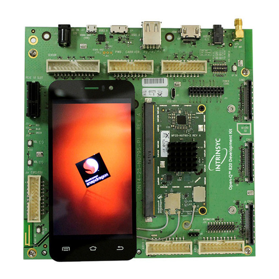
Page 10: Hardware Identification Label
Open-Q™ 820 Development Kit based on the Snapdragon™ 820 (APQ8096) Processor User Guide Version 2.0 Figure 1 Assembled Open-Q 820 Development Kit The development kit comes with Android 6.0 (Marshmallow) software pre-programmed on the CPU board (SOM). Please contact Intrinsyc for availability of camera modules, sensor boards, and other accessories: sales@intrinsyc.com 3.5 Hardware Identification Label... - Page 11 To register a development kit, please visit: http://support.intrinsyc.com/account/register Mini-ITX form-factor carrier board: • Serial Number Note: Please retain the SOM and carrier board serial number for warranty purposes. Copyright Intrinsyc Technologies Corporation...
-
Page 12: System Block Diagram
Open-Q™ 820 Development Kit based on the Snapdragon™ 820 (APQ8096) Processor User Guide Version 2.0 3.6 System Block Diagram The Open-Q 820 development platform consists of three major components • Open-Q 820 SOM • Carrier board for I/O and connecting with external peripherals •... -
Page 13: Som Mechanical Properties
3.7.2 SOM Block Diagram The Open-Q 820 SOM measuring 42mm x 82mm is where all the processing occurs. It is connected to the carrier via a 314-pin MXM Gen-III edge connector. The purpose of this edge connector is to bring out essential signals such that other peripherals can interface with the platform. -
Page 14: Hardware Specification
QSPI QSPI BPLSs / MPPs / GPIOs BOOT CONFIG UART Open-Q™ 820 JTAG System on Module Carrier Board Figure 4 SOM Block Diagram 3.7.3 Hardware Specification The Open-Q™ 820 SOM platform encompasses the following hardware features: Copyright Intrinsyc Technologies Corporation... - Page 15 PCI Express Specification, Rev module. PCIe 1, 2 routed out of Connectors 1 x MXM SOM Connector for SOM 314 pin edge connector connector 1 x SOM to Carrier B2B connector for SOM and 100 pin board to board Copyright Intrinsyc Technologies Corporation...
-
Page 16: Som Rf Specification For Wifi, Bt, Gps
For details on connecting the WiFi module to the on board PCB antennas on the carrier board, refer to section 3.8.14 below. WGR7640: GPS Front End WGR7640 is the primary GPS radio interface used on the Open-Q 820 development kit. This provides the RF capabilities for GNSS functions. -
Page 17: Open-Q™ Carrier Board
Open-Q™ 820 Development Kit based on the Snapdragon™ 820 (APQ8096) Processor User Guide Version 2.0 3.8 Open-Q™ Carrier Board The Open-Q 820 Carrier board is a Mini-ITX form factor board with various connectors used for connecting different peripherals. The following are the mechanical properties of the carrier board:... -
Page 18: Open-Q™ 820 Carrier Board Expansion Connectors
SMD Button Volume – Key Sensor IO Connector (DNP) 24 pin Sensor Expansion Connectors Support any user sensor card, Available via Intrinsyc optional Supports Gen-9 sensor connector as Standard 44-pin ST Micro PLCC accessories kit stuff option support via optional daughter card... - Page 19 Connector for Qualcomm’s internal 60 pin connector sensor Gen 10 To interface with Qualcomm’s sensor boards internal sensor boards (for Intrinsyc internal use only – not supported) VIP Extension connector Connector for interfacing with 60-pin connector To connect to Qualcomm legacy...
-
Page 20: Open-Q Power Specification
3.8V constant power input to the SOM. • Support for battery charging over external charger is not implemented in the design. Please contact Intrinsyc for such customization. PM8996 PMIC is used for: • Source various regulated power rails •... -
Page 21: Power Probe Header J86
PC, the following cable (or similar) is needed http://www.digikey.ca/product-detail/en/TTL-232R-RPI/768-1204-ND/4382044 Table 3.8-4 Debug UART Header J61 Pin-out Description Signal FTDI RPI cable connection APQ UART RX (GPIO5) BLSP8_UART_RX J61[1] Orange APQ UART TX (GPIO4) BLSP8_UART_TX J61[2] Yellow J61[3] Black Copyright Intrinsyc Technologies Corporation... -
Page 22: Debug Serial Uart Over Usb J22
Figure 8 J22 Debug UART over USB The UART connection used on the Open-Q 820 is a USB micro B connector (J22). This debug UART is available over USB via the FTDI FT232RQ chip on the carrier board. To get the serial terminal working with a PC, user needs to ensure that the appropriate FTDI drivers are installed. -
Page 23: Sensor Io Expansion Header J53
Table 3.8-6 Sensor Expansion Header J53 Pin out Description Signal Description Signal SSC I2C-3 serial data SSC_I2C_3_SDA J53[1] Accelerometer interrupt ACCEL_INT_N J53[2] input to processor via GPIO117 SSC I2C-3 serial clock SSC_I2C_3_SCL J53[3] Cap interrupt input to CAP_INT_N J53[4] processor via GPIO123 Copyright Intrinsyc Technologies Corporation... - Page 24 BLSP5 for UART/ SPI/ I2C/ UIM. Please refer to the schematic and consider the power before connecting anything to this header. Note that there is an unpopulated Gen-10 connector header (J55) footprint at the bottom of the carrier board. Install the Samtec (part number: QSH-030-01-L-D-A) connector here if needed. Copyright Intrinsyc Technologies Corporation...
-
Page 25: Nfc Expansion Header J52 (Exp1)
This header also allows user to connect to the free GPIOs and I2C lines when NFC is not used; therefore, enabling other use cases. Please refer to Table 3.8-7 for detailed information regarding the signals that are being brought out by this connector. - Page 26 BLSP9 3 bit via APQ GPIO49 NFC_BLSP9_SPI J52[20] _CS_N _MOSI In general, if there is no need for NFC application, this expansion header can provide two GPIOs, I2C, free running clocks, and enable voltage/ power source to external peripherals. Copyright Intrinsyc Technologies Corporation...
-
Page 27: Education / Gpio Header J54 (Exp2)
150mA BLSP1_3_3P3(3.3V) BLSP1_SPI_MOS J54[3] VDD_EXP2 (Default 3.3V VDD_EXP2 J54[4] I (APQ-GPIO0) Power Supply) max 300mA BLSP1_2_3P3(3.3V) BLSP1_SPI_MIS J54[5] PM8996 MPP GPIO2 PM_MPP02 J54[6] O (APQ-GPIO1) BLSP1_1_3P3(3.3V) BLSP1_SPI_CS_ J54[7] PM8996 MPP GPIO4 PM_MPP04 J54[8] N (APQ-GPIO2) Copyright Intrinsyc Technologies Corporation... -
Page 28: Anc Headset Jack J27
3.8.11 ANC Headset Jack J27 Figure 14 ANC Headphone Jack The ANC headset jack (J27) is a special 3.5mm TRRS jack with ANC capabilities. It is backwards compatible with standard headset jacks. Please contact Intrinsyc at sales@intrinsyc.comfor compatible ANC headsets. Copyright Intrinsyc Technologies Corporation... -
Page 29: Audio Inputs Expansion Header J50
Clock for digital MIC 1 and 2 CDC_DMIC_CLK0 J50[13] Clock for digital MIC 3 and 4 CDC_DMIC_CLK1 J50[14] Digital MIC 1 and 2 data line CDC_DMIC_DATA0 J50[15] Digital MIC 3 and 4 data line CDC_DMIC_DATA J50[16] Copyright Intrinsyc Technologies Corporation... -
Page 30: Audio Outputs Expansion Header J26
Analog audio line out 2, CDC_LINE_OUT2_P J26[3] Analog audio line out 2, CDC_LINE_OUT2_N J26[4] positive differential output negative differential output Audio line outputs 3 and 4 CDC_LINE_REF J26[5] 3.3V output power supply MB_VREG_3P3 J26[6] GND reference Copyright Intrinsyc Technologies Corporation... -
Page 31: On Board Pcb Wlan Antennas
The Open-Q™ 820 carrier board allows user the flexibility of using an external (via SMA connector) or an on board PCB GPS antenna. Depending on which antenna is used, dip switch S10 needs to be configured (see table below for details). Copyright Intrinsyc Technologies Corporation... -
Page 32: Open-Q Display
HDMI monitor/ television via an HDMI cable. As part of a new feature, the APQ8096 can now support up to 4K UHD (3840 x 2400 at 60fps) and HDMI 2.0 (4K60)/ 4K30 Miracast. Please note that the Open-Q 820 Development kit is for evaluation purposes only and may not be HDMI compliant. -
Page 33: Display Connector J2
Supports I2C or SPI via BLSP1 and SSC_5 o Can chose between I2C or SPI signals via MUX Power specifications The display connector supports the following power domains: Display Signal Power Domain PM8996 LDO22 (3.3-2.8V) up to 150 mA Copyright Intrinsyc Technologies Corporation... - Page 34 J7 allows users to access the display signals on the carrier board (display connector J2) via connector J8 on the display board. Note: The display board comes as an additional add-on to the Open-Q 820 development kit. To purchase this, please visit http://shop.intrinsyc.com...
- Page 35 100-pin ERM8 connector, directly connects to the FWVGA LCD panel. See the section below for more details on this LCD panel. It is important to note that connector J1 of the display board needs to connect to J2 of the carrier board for this configuration to work. Copyright Intrinsyc Technologies Corporation...
- Page 36 Note: The display above when mounted on the Intrinsyc Open-Q 820 Display Adapter is meant to work with the carrier board. Altering the use of this LCD panel is not recommended. Note: 225-0100 display adapter boards are currently end of life. The new Open-Q 820 Intrinsyc Display adapter board (part number: 280-0100) has the same specifications (as described above) and pin-outs as 225-0100.
-
Page 37: Pci Express 1X Slot J30
Open-Q™ 820 Development Kit based on the Snapdragon™ 820 (APQ8096) Processor User Guide Version 2.0 3.8.19 PCI Express 1X Slot J30 The PCI Express slot (J30) used on the Open-Q 820 development kit is a standard PC style half- height card slot. It allows for external peripheral connectivity such as Gigabit Ethernet, Gigabit Wi- Fi, or PCIe based audio / video processors. - Page 38 Please check the software compatibility before connecting any PCI Express mini cards. Note: The pin-outs of this connector comply with the PCI Express mini card standards. Please refer to the document at the following link for more information: https://www.pcisig.com/specifications/pciexpress/base/#mini1.2 Figure 21 J72 Mini PCIe Connector Copyright Intrinsyc Technologies Corporation...
-
Page 39: Camera Connectors
Mounting holes for full size card Figure 22 J72 Mounting holes for Mini PCIe Connector 3.8.21 Camera connectors The Open-Q 820 development kit supports three 4-lane MIPI camera interfaces via three separate JAE 41-pin connectors. The following are some features of the camera connectors: •... - Page 40 (this is not a generic I2C port). CCI_I2C_SDA0 CCI_I2C_SDA0 CCI_I2C_SDA0 Input / output. Connected to APQ8096. (APQ_GPIO17) (APQ_GPIO17) (APQ_GPIO17) Default use is for camera CCI0 I2C data interface (this is not a generic I2C port). Copyright Intrinsyc Technologies Corporation...
- Page 41 Table 3.8.21-2. MIPI CSI Camera Use Cases CSI PHY Use case Comment CSI0 Up to 4 lane One Camera of 4 lane or One camera of 3 lane One Camera of 2 lane One Camera of 1 lane Copyright Intrinsyc Technologies Corporation...
-
Page 42: Power Header Via 20 Pin Connector J60
VREG_L23A_2P8 J60[3] J60[4] for camera 0, 2 (VDD) J60[5] 3.3V power rail MB_VREG_3P3 J60[6] for camera 0, 1, 2 1.05V power rail MB_ELDO_CAM1_DVDD J60[7] 2.85V power rail VREG_L18A_2P85 J60[8] for camera 1 for camera 1 (AVDD) Copyright Intrinsyc Technologies Corporation... - Page 43 Table 3.8.23-1. General System J59 Pin Out Description Signal Description Signal Power rail to support I2C CONFIG_I2C_PWR J26[1] J26[2] signals coming from an external source clock signal from CONFIG_I2C_SCL J26[3] J26[4] external source to Semtech GPIO expander Copyright Intrinsyc Technologies Corporation...
- Page 44 Figure 25 J73 Ethernet AVB Expansion Header This header is used for interfacing with automotive peripherals via Ethernet AVB standard. Note that this is used for Intrinsyc internal testing and is not supported. 3.8.25 VIP Expansion Header J71 Figure 26 J71 VIP Expansion Header This header is used for interfacing with Qualcomm legacy automotive VIP boards.
Need help?
Do you have a question about the Open-Q 820 and is the answer not in the manual?
Questions and answers