Table of Contents
Advertisement
Quick Links
Open-X™ 8M Development Kit based on the NXP
i.MX8™ Processor
User Guide
[Document: ITC-01RND1319-UG-001 Version: 1.0]
Your use of this document is subject to and governed by those terms and conditions in the Intrinsyc Purchase an Open-X™ 8M Development Kit based
on the NXP Semiconductors i.MX 8M™ Processor and Software License Agreement for the Open-X 8M Development Kit, which you or the legal entity
you represent, as the case may be, accepted and agreed to when purchasing an Open-X Development Kit from Intrinsyc Technologies Corporation
("Agreement"). You may use this document, which shall be considered part of the defined term "Documentation" for purposes of the Agreement, solely
in support of your permitted use of the Open-X 8M Development Kit under the Agreement. Distribution of this document is strictly prohibited without
the express written permission of Intrinsyc Technologies Corporation and its respective licensors, which they can withhold, condition or delay in its sole
discretion.
Intrinsyc is a trademark of Intrinsyc Technologies Corporation., registered in Canada and other countries.
NXP Semiconductors N.V. and i.MX 8M are trademarks of NXP Semiconductors N.V., registered in the Netherlands and other countries. Other product
and brand names used herein may be trademarks or registered trademarks of their respective owners.
This document contains technical data that may be subject to U.S. and international export, re-export, or transfer ("export") laws. Diversion contrary to
U.S. and international law is strictly prohibited.
Advertisement
Table of Contents

Related Manuals for Intrinsyc Open-X 8M


Summary of Contents for Intrinsyc Open-X 8M
- Page 1 [Document: ITC-01RND1319-UG-001 Version: 1.0] Your use of this document is subject to and governed by those terms and conditions in the Intrinsyc Purchase an Open-X™ 8M Development Kit based on the NXP Semiconductors i.MX 8M™ Processor and Software License Agreement for the Open-X 8M Development Kit, which you or the legal entity you represent, as the case may be, accepted and agreed to when purchasing an Open-X Development Kit from Intrinsyc Technologies Corporation (“Agreement”).
- Page 2 Open-X™ 8M Development Kit based on the NXP i.MX8™ Processor User Guide Version 1.0 IDENTIFICATION Document Title Open-X™ 8M Development Kit based on the NXP i.MX8™ Processor User Guide Document Number ITC-01RND1319-UG-001 Version Date May 3, 2018 History REVISION DATE DESCRIPTION PAGES May 3, 2018 Initial release Copyright Intrinsyc Technologies Corporation...
-
Page 3: Table Of Contents
SOM RF Specification for WIFI, BT ............... 14 Open-X 8M Carrier Board ................ 15 Boot dip switch Configuration Options ..............15 Open-X 8M Carrier Board Expansion Connectors ..........16 Open-X 8M Power Specification ................18 Power Probe Header J600 ..................19 Debug Serial UART over USB J800 ............... -
Page 4: Introduction
Development Kit based on the NXP i.MX8™ Processor For more background information on this development kit, visit: https://www.intrinsyc.com/imx- embedded-development-kits/open-x-8m-development-kit/ 1.2 Scope This document will cover the following items on the Open-X 8M: • Block Diagram and Overview • Hardware Features • Configuration • SOM •... -
Page 5: Documents
Open-X™ 8M Development Kit based on the NXP i.MX8™ Processor User Guide Version 1.0 2. DOCUMENTS This section lists the supplementary documents for the Open-X 8M development kit. 2.1 Applicable Documents REFERENCE TITLE Intrinsyc Purchase and Software License Agreement for the Open-X Development 2.2 Reference Documents... -
Page 6: List Of Figures
Open-X™ 8M Development Kit based on the NXP i.MX8™ Processor User Guide Version 1.0 2.4 List of Figures Figure 3-1 Assembled Open-X 8M Development Kit ................8 Figure 3-2 Open-X 8M Block Diagram ....................10 Figure 3-3 Open-X 8M SOM ....................... 11 Figure 3-4 SOM Block Diagram ...................... -
Page 7: Open-X 8M Development Kit
3. OPEN-X 8M DEVELOPMENT KIT 3.1 Introduction The Open-X 8M provides a quick reference or evaluation platform for NXP Semiconductors latest processor series, the i.MX 8M. This kit is suited for Android or Linux application developers, multimedia audio or video vendors, voice processing vendors, consumer product manufacturers, OEMs, hardware component vendors, video surveillance, and camera vendors to evaluate, optimize, test and deploy applications that can utilize the NXP Semiconductors i.MX8 series technology. -
Page 8: Kit Contents
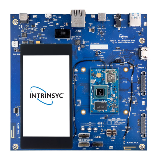
AC power adapter and HDMI cable Figure 3-1 Assembled Open-X 8M Development Kit The development kit comes with Android software pre-programmed on the CPU board (SOM). Please contact Intrinsyc for availability of camera modules, sensor boards, and other accessories: sales@intrinsyc.com Copyright Intrinsyc Technologies Corporation... -
Page 9: Hardware Identification Label
To register a development kit, please visit: http://support.intrinsyc.com/account/register Carrier board: • Serial Number Note: Please retain the SOM and carrier board serial number for warranty purposes. Copyright Intrinsyc Technologies Corporation... -
Page 10: System Block Diagram
Open-X™ 8M Development Kit based on the NXP i.MX8™ Processor User Guide Version 1.0 3.6 System Block Diagram The Open-X 8M development platform consists of three major components: • Open-X 8M SOM • Carrier board for I/O and connecting with external peripherals •... -
Page 11: Open-X 8M Som
• 16 GB eMMC Flash storage • MC34PF4210A1ES – PMIC for Peripheral LDOs, Boost Regulators • QCA6174A-1 Wi-Fi + BT pre-certified module over PCIe, UART, PCM 55mm 35mm Figure 3-3 Open-X 8M SOM SOM Mechanical Properties Area 19.25 cm (55 mm x 35 mm) -
Page 12: Som Block Diagram
Open-X™ 8M Development Kit based on the NXP i.MX8™ Processor User Guide Version 1.0 SOM Block Diagram The Open-X 8M SOM measuring 55mm x 35mm is where all the processing occurs. It is connected to the carrier via 3 100-pin B2B connectors. -
Page 13: Hardware Specification
Open-X™ 8M Development Kit based on the NXP i.MX8™ Processor User Guide Version 1.0 Hardware Specification The Open-X 8M SOM platform encompasses the following hardware features: Table 3.7.3-1 Open-X 8M SOM Hardware Features Subsystem / Connectors Feature Set Description Specification... -
Page 14: Som Rf Specification For Wifi, Bt
2AFDI-ITCNFA324 for details). Please note that the on-board PCB antennas were not the antennas used for the SOM WiFi/BT module certification. For details on connecting the WiFi module to the on-board PCB antennas on the carrier board, refer to section below. Copyright Intrinsyc Technologies Corporation... -
Page 15: Open-X 8M Carrier Board
Display: 100 pin carrier board connector Boot dip switch Configuration Options Two dip switches on the Open-X 8M carrier board provides the user options to configure the boot mode and boot device. The table below show the supported boot modes on the Open-X 8M... -
Page 16: Open-X 8M Carrier Board Expansion Connectors
Open-X™ 8M Development Kit based on the NXP i.MX8™ Processor User Guide Version 1.0 Open-X 8M Carrier Board Expansion Connectors Table 3.8.2-1 lists the connectors, expansions and their usages on the carrier board: Table 3.8.2-1 Carrier Board Expansion options and their usage... - Page 17 The information listed below is of particular use for those who want to interface other external hardware devices with the Open-X 8M. Before connecting anything to the development kit, please ensure the device meets the specific hardware requirements of the processor.
-
Page 18: Open-X 8M Power Specification
Open-X 8M Power Specification The Open-X 8M development kit power source is provided by either the 12V DC barrel jack, or the USB Type-C jack. From either the power jack or the USB Type-C jack, the power input branches off into different voltage rails via step down converters on the carrier board and a Power management IC (PMIC) on the SOM. -
Page 19: Power Probe Header J600
(typically 30 minutes). The SOM power consumption can then be calculated using the following formula (where Rsense = 5 milliohms): ����������������� − ���������������� � ���������������� = ���������������� ∗ � � ������������_������������_��������������������_���� ������������_������������_��������������������_���� ������������������������ ������������_������������_��������������������_���� Copyright Intrinsyc Technologies Corporation... -
Page 20: Debug Serial Uart Over Usb J800
Debug Serial UART over USB J800 Figure 3-9 Debug UART over USB J800 The UART connection used on the Open-X 8M is a USB micro B connector (J800). The debug UART is available over USB via the SILICON LABS CP2105 chip on the carrier board. -
Page 21: Jtag Header J801
Processor accepts five JATG signals from an attached debugging device on dedicated pins. A sixth pin on the processor accepts a board HW configuration input, specific to the Open-X 8M board. Note: Intrinsyc does not provide software support for JTAG. -
Page 22: Microsd Card Socket J900
Figure 3-12 SD Card on Carrier Board J900 The SD2 interface is designed to support: • SD/SDIO standard, up to version 3.0. • 1.8 V and 3.3 V operation, but do not support 1.2 V operation. • 4-bit SD and SDIO modes Copyright Intrinsyc Technologies Corporation... -
Page 23: Buttons And Leds
Open-X™ 8M Development Kit based on the NXP i.MX8™ Processor User Guide Version 1.0 Buttons and LEDs There is one user interface, one reset and one power button on the Open-X 8M carrier board. Figure 3-13 Buttons and LEDs The chip supports the use of a button input signal to request main SoC power state changes (i.e. ON or OFF) from the PMU. -
Page 24: Usb Type-C J1300 And Type-A J1301
USB Type-C J1300 and Type-A J1301 The i.MX 8MDQLQ Applications Processors contains two USB 2.0/3.0 OTG controllers, with two integrated USB PHYs. On the Open-X 8M development kit, one is used for the USB Type-A host port and the other for the USB Type-C port. -
Page 25: Audio Stereo Line-Out Jack J1200
Figure 3-16 3.5mm Audio Line-out Jack J1200 The main Audio DAC used on the Open-X 8M board is the CIRRUS LOGIC Low Power, high quality Stereo DAC, WM8524. The 3.5mm audio jack (J1200) is a 3.5mm CTIA standard pinout TRRS jack. -
Page 26: Digital Audio Expansion Headers
SAI1 TX Data 5 SAI1_TXD5 J1800 [14] SAI1 TX Data 6 SAI1_TXD6 J1800 [15] SAI1 TX Data 7 SAI1_TXD7 J1800 [16] J1800 [17] SAI1 RX Clock SAI1_RXC J1800 [18] SAI1 RX Frame Sync SAI1_RXFS J1800 [19] Copyright Intrinsyc Technologies Corporation... - Page 27 [52] NAND_nWE J1800 [53] NAND_nWP J1800 [54] NAND_nREADY J1800 [55] NAND Data 4 NAND_DATA_4 J1800 [56] NAND Data 5 NAND_DATA_5 J1800 [57] NAND Data 6 NAND_DATA_6 J1800 [58] NAND Data 7 NAND_DATA_7 J1800 [59] J1800 [60] Copyright Intrinsyc Technologies Corporation...
- Page 28 These 0.05mm pitch headers provide all of the same signals that are available on the 60 pin FPC connector and are provided to make it easier for users to connect to individual signals if desired: 1. 3 SAI 2. SPDIF 3. I2C 4. NAND Copyright Intrinsyc Technologies Corporation...
- Page 29 SAI3_RXD J1803 J1803 NAND_nREADY SAI3_RXFS J1803 J1803 [10] NAND_nWE J1803 [11] J1803 [12] NAND_DATA_7 NAND_nWP J1803 [13] J1803 [14] NAND_DATA_6 I2C3_SCL J1803 [15] J1803 [16] NAND_DATA_5 I2C3_SDA J1803 [17] J1803 [18] NAND_DATA_4 J1801 [19] J1801 [20] Copyright Intrinsyc Technologies Corporation...
-
Page 30: On Board Pcb Wlan Antenna
The Open-X 8M carrier board has two dual-band (2.4GHz & 5GHz) WLAN/Bluetooth PCB trace antennas. These antennas connect to the QCA6174A WiFi module on the SOM via coaxial cables that attach to MH4L receptacles. The Open-X 8M Development Kit comes complete with the two coaxial cables installed. -
Page 31: Open-X Display Interfaces
HDMI monitor or television via a standard HDMI cable. The Open-X 8M can support up to 4K UHD (4096 x 2160 at 60 Hz) and HDMI 2.0 a. Please note that the Open-X 8M Development kit is for evaluation purposes only and may not be HDMI standard compliant. - Page 32 • Touch Panel Support – supports I2C touch controllers • Additional GPIOs for general purposes available. Note: Please refer to the carrier board schematic and Display Board Design Guide document when designing a custom display interface board. Copyright Intrinsyc Technologies Corporation...
- Page 33 J1700 on the carrier board. This board allows users to interface with the development kit via the LCD display panel and touchscreen. Note: The display board comes as an optional add-on to the Open-X 8M development kit. To purchase this, please visit http://shop.intrinsyc.com...
-
Page 34: Ethernet Connector J1400
There is one Gigabit Ethernet port on the i.MX 8MDQLQ processor. The developer can use the Ethernet connector to send/receive the ENET signals. The Ethernet PHY of the Open-X 8M carrier board is provided by the Qualcomm AR8031 Ethernet transceiver chip (U1400) which interfaces to the i.MX 8M processor via standard RGMII Ethernet signals. -
Page 35: Key E Pci Express Slot J1100
M.2 Key E PCI Express Slot J1100 The M.2 Key E PCI Express slot (J1100) used on the Open-X 8M development kit is a standard PC style half-height card slot. It allows for external peripheral connectivity such as Wi-Fi / Bluetooth, or PCIe based audio / video processors. -
Page 36: Camera Connectors
Open-X™ 8M Development Kit based on the NXP i.MX8™ Processor User Guide Version 1.0 Camera connectors The Open-X 8M development kit supports two 4-lane MIPI camera interfaces via two separate JAE 41-pin connectors. The following are some features of the camera connectors: •... - Page 37 3 12,18,35,3 Not Used 6,37,38,39 ,40,41 Note: A connection from the camera connectors on the carrier board to the camera adapter board is established by a 41-pin cable assembly from JAE Electronics (part number JF08R0R041020MA) Copyright Intrinsyc Technologies Corporation...
-
Page 38: 3-Pin 5V Dc Fan Connector
The tachometer is not routed back to the SOM and the fan uses a constant 5V DC so speed control is not an option. If these features are required, contact Intrinsyc for customization.
Need help?
Do you have a question about the Open-X 8M and is the answer not in the manual?
Questions and answers