
Related Manuals for Holtek HT66F20-1


Summary of Contents for Holtek HT66F20-1
-
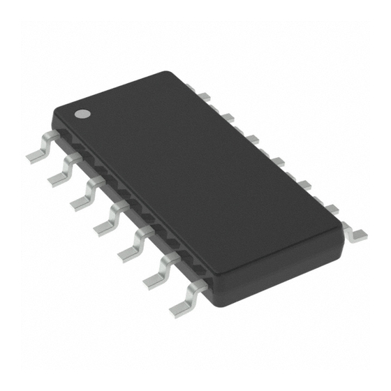
Page 1: 1�-Pin �Sop (150�Il) Outline Di�Ensions
Flash MCU with EEPROM HT66F20-1/HT66F30-1 HT68F20-1/HT68F30-1 Revision: V1.40 Date: �ove��e� ��� �01� �ove��e� ��� �01�... -
Page 2: Table Of Contents
HT66F20-1/HT66F30-1/HT68F20-1/HT68F30-1 Flash MCU with EEPROM Table of Contents Features ......................7 CPU Featu�es ......................... 7 Pe�iphe�al Featu�es ......................... 7 General Description ..................8 Selection Table ....................8 Block Diagram ....................9 Pin Assignment ....................10 Pin Description ....................12 Absolute Maximum Ratings ................16 D.C. - Page 3 HT66F20-1/HT66F30-1/HT68F20-1/HT68F30-1 Flash MCU with EEPROM Special Function Register Description ............35 Indi�ect Add�essing Registe�s – IAR0� IAR1 ................. �5 Me�o�y Pointe�s – MP0� MP1 ....................�5 Bank Pointe� – BP ......................... �� Accu�ulato� – ACC ....................... �� P�og�a� Counte� Low Registe� – PCL .................. ��...
- Page 4 HT66F20-1/HT66F30-1/HT68F20-1/HT68F30-1 Flash MCU with EEPROM Input/Output Ports ..................71 I/O Po�t Registe� List ......................71 Pull-high Resisto�s ........................ 7� Po�t A Wake-up ........................7� I/O Po�t Cont�ol Registe�s ..................... 7� Pin-�e�apping Functions ...................... 74 Pin-�e�apping Registe�s ....................... 74 I/O Pin St�uctu�es ........................75 P�og�a��ing Conside�ations ....................
-
Page 5: A�Ith�Etic And Logic Unit - Alu
HT66F20-1/HT66F30-1/HT68F20-1/HT68F30-1 Flash MCU with EEPROM Analog to Digital Converter ................ 131 A/D Ove�view ........................1�1 A/D Conve�te� Registe� Desc�iption ..................1�1 A/D Conve�te� Data Registe�s – ADRL� ADRH ..............1�� A/D Conve�te� Cont�ol Registe�s – ADCR0� ADCR1� ACERL ..........1��... - Page 6 HT66F20-1/HT66F30-1/HT68F20-1/HT68F30-1 Flash MCU with EEPROM Low Voltage Detector – LVD ............... 178 LVD Registe� ........................178 LVD Ope�ation ........................179 SCOM Function for LCD ................180 LCD Ope�ation ........................180 LCD Bias Cont�ol ........................ 181 Configuration Options ................. 182 Application Circuits ..................183 HT��F�0-1/HT��F�0-1 .......................
-
Page 7: Features
• True EEPROM Memory: 32×8 ~ 64×8 • Watchdog Timer function • Up to 22 bidirectional I/O lines • Software controlled 4-SCOM lines LCD driver with 1/2 bias • Dual pin-shared external interrupts • Multiple Timer Module for time measure, input capture, compare match output, PWM output or single pulse output function • Serial Interfaces Module with Dual SPI and I C interfaces • Dual Comparator functions • Dual Time-Base functions for generation of fixed time interrupt signals • 8-channel 12-bit resolution A/D converter – HT66F30-1/HT66F20-1 • Low voltage reset function • Low voltage detect function • Wide range of available package types • Flash program memory can be re-programmed up to 100,000 times • Flash program memory data retention > 10 years • True EEPROM data memory can be re-programmed up to 1,000,000 times • True EEPROM data memory data retention > 10 years Rev. 1.40 �ove��e� ��� �01�... -
Page 8: General Description
HT66F20-1/HT66F30-1/HT68F20-1/HT68F30-1 Flash MCU with EEPROM General Description The HT66Fx0-1 and HT68Fx0-1 series are Flash Memory type with 8-bit high performance RISC architecture microcontrollers, designed for a wide range of applications. Offering users the convenience of Flash Memory multi-programming features, these devices also include a wide range of functions and features. Other memory includes an area of RAM Data Memory as well as an area of true EEPROM memory for storage of non-volatile data such as serial numbers, calibration data etc. Analog features include a multi-channel 12-bit A/D converter and dual comparator functions. Multiple and extremely flexible Timer Modules provide timing, pulse generation and PWM generation functions. Communication with the outside world is catered for by including fully... -
Page 9: Block Diagram
HT66F20-1/HT66F30-1/HT68F20-1/HT68F30-1 Flash MCU with EEPROM Block Diagram L o w W a t c h d o g V o l t a g e T i m e r D e t e c t R e s e t... -
Page 10: Pin Assignment
HT66F20-1/HT66F30-1/HT68F20-1/HT68F30-1 Flash MCU with EEPROM Pin Assignment HT66F20-1 & HT66F30-1 P A 0 / C 0 X / T P 0 _ 0 / A N 0 P A 1 / T P 1 _ 0 / A N 1 V S S &... - Page 11 HT66F20-1/HT66F30-1/HT68F20-1/HT68F30-1 Flash MCU with EEPROM HT68F20-1 & HT68F30-1 P A 0 / C 0 X / T P 0 _ 0 P A 1 / T P 1 _ 0 V S S P A 2 / T C K 0 / C 0 +...
-
Page 12: Pin Description
HT66F20-1/HT66F30-1/HT68F20-1/HT68F30-1 Flash MCU with EEPROM Pin Description The function of each pin is listed in the following table, however the details behind how each pin is configured is contained in other sections of the datasheet. HT66F20-1 Pin Name Function Pin-Shared Mapping PAWU PA0~PA7 Po�t A CMOS — PAPU PB0~PB5 Po�t B PBPU CMOS — PC0~PC� Po�t C PCPU CMOS — A�0~A�7 ADC input ACERL A� —... - Page 13 HT66F20-1/HT66F30-1/HT68F20-1/HT68F30-1 Flash MCU with EEPROM HT66F30-1 Pin Name Function Pin-Shared Mapping PAWU PA0~PA7 Po�t A CMOS — PAPU PB0~PB5 Po�t B PBPU CMOS — PC0~PC7 Po�t C PCPU CMOS — A�0~A�7 ADC input ACERL A� — PA0~PA7 VREF ADC �efe�ence input ADCR1 A�...
- Page 14 HT66F20-1/HT66F30-1/HT68F20-1/HT68F30-1 Flash MCU with EEPROM HT68F20-1 Pin Name Function Pin-Shared Mapping PAWU PA0~PA7 Po�t A CMOS — PAPU PB0~PB5 Po�t B PBPU CMOS — PC0~PC� Po�t C PCPU CMOS — C0-� C1- Co�pa�ato� 0� 1 input A� — PA�� PC�...
- Page 15 HT66F20-1/HT66F30-1/HT68F20-1/HT68F30-1 Flash MCU with EEPROM HT68F30-1 Pin Name Function Pin-Shared Mapping PAWU PA0~PA7 Po�t A CMOS — PAPU PB0~PB5 Po�t B PBPU CMOS — PC0~PC7 Po�t C PCPU CMOS — C0-� C1- Co�pa�ato� 0� 1 input A� — PA�� PC�...
-
Page 16: Absolute Maximum Ratings
HT66F20-1/HT66F30-1/HT68F20-1/HT68F30-1 Flash MCU with EEPROM Absolute Maximum Ratings Supply Voltage ....................V −0.3V to V +6.0V Input Voltage ....................V −0.3V to V +0.3V Storage Temperature ....................-50˚C to 125˚C Operating Temperature ....................-40˚C to 85˚C Total ............................-80mA Total ............................. 80mA Total Power Dissipation ......................500mW Note: These are stress ratings only. Stresses exceeding the range specified under "Absolute Maximum Ratings" may cause substantial damage to these devices. Functional operation of these devices at other conditions beyond those listed in the specification is not implied and prolonged exposure to extreme conditions may affect devices reliability. D.C. Characteristics HT66F20-1/HT66F30-1 Ta=25˚C Test Conditions Symbol Parameter Min. Typ. Max. - Page 17 HT66F20-1/HT66F30-1/HT68F20-1/HT68F30-1 Flash MCU with EEPROM Test Conditions Symbol Parameter Min. Typ. Max. Unit Conditions Input Low Voltage fo� I/O Po�ts o� — — — 0.�V Input Pins except RES pin Input High Voltage fo� I/O Po�ts o� — — 0.7V —...
- Page 18 HT66F20-1/HT66F30-1/HT68F20-1/HT68F30-1 Flash MCU with EEPROM HT68F20-1/HT68F30-1 Ta=25˚C Test Conditions Symbol Parameter Min. Typ. Max. Unit Conditions =8MHz �.� — Ope�ating Voltage — =1�MHz �.7 — (HXT� ERC� HIRC) =�0MHz — �V — �A �o load� f =4MHz� WDT ena�le —...
-
Page 19: A.c. Characteristics
HT66F20-1/HT66F30-1/HT68F20-1/HT68F30-1 Flash MCU with EEPROM Test Conditions Symbol Parameter Min. Typ. Max. Unit Conditions LVR ena�le� LVDE�=0 — �0 μA Additional Powe� Consu�ption if — LVR disa�le� LVDE�=1 — μA LVR and LVD is used LVR ena�le� LVDE�=1 — 1�5 μA... - Page 20 HT66F20-1/HT66F30-1/HT68F20-1/HT68F30-1 Flash MCU with EEPROM Test Conditions Symbol Parameter Min. Typ. Max. Unit Conditions Ta=25˚C, R=120kΩ* -�% +�% Ta=0~70˚C, R=120kΩ* +�% Syste� Clock (ERC) Ta=-40˚C~85˚C, R=120kΩ* �.0V~5.5V Ta=-40˚C~85˚C, R=120kΩ* +10% MHz �.�V~5.5V Ta=-40˚C~85˚C, R=120kΩ* -15% +10% MHz Syste� Clock (LXT) —...
- Page 21 HT66F20-1/HT66F30-1/HT68F20-1/HT68F30-1 Flash MCU with EEPROM HT68F20-1/HT68F30-1 Ta=25˚C Test Conditions Symbol Parameter Min. Typ. Max. Unit Conditions �.�V~5.5V — Ope�ating Clock — �.7V~5.5V — 1� 4.5V~5.5V — �0 �.�V~5.5V — Syste� Clock (HXT) — �.7V~5.5V — 1� 4.5V~5.5V — �0 �V/5V Ta=25˚C...
-
Page 22: A/D Converter Characteristics
HT66F20-1/HT66F30-1/HT68F20-1/HT68F30-1 Flash MCU with EEPROM A/D Converter Characteristics HT66F20-1/HT66F30-1 Ta=25˚C Test Conditions Symbol Parameter Min. Typ. Max. Unit Condition A/D Conve�te� Ope�ating Voltage — — �.7 — A/D Conve�te� Input Voltage — — — A/D Conve�te� Refe�ence Voltage — —... -
Page 23: Power On Reset Electrical Characteristics
HT66F20-1/HT66F30-1/HT68F20-1/HT68F30-1 Flash MCU with EEPROM Power on Reset Electrical Characteristics Ta=25˚C Test Conditions Symbol Parameter Min. Typ. Max. Unit Condition Sta�t Voltage to ensu�e Powe�-on Reset — — — — �V Rise Rate to ensu�e Powe�-on Reset — — 0.0�5 —... - Page 24 HT66F20-1/HT66F30-1/HT68F20-1/HT68F30-1 Flash MCU with EEPROM S Y S ( S y s t e m C l o c k ) P h a s e C l o c k T 1 P h a s e C l o c k T 2...
-
Page 25: Stack
HT66F20-1/HT66F30-1/HT68F20-1/HT68F30-1 Flash MCU with EEPROM needed to pre-fetch. Stack This is a special part of the memory which is used to save the contents of the Program Counter only. The stack has four levels and is neither part of the data nor part of the program space, and is neither readable nor writeable. The activated level is indexed by the Stack Pointer, and is neither readable nor writeable. At a subroutine call or interrupt acknowledge signal, the contents of the Program Counter are pushed onto the stack. At the end of a subroutine or an interrupt routine, signaled by a return instruction, RET or RETI, the Program Counter is restored to its previous value from the stack. After a device reset, the Stack Pointer will point to the top of the stack. If the stack is full and an enabled interrupt takes place, the interrupt request flag will be recorded but the acknowledge signal will be inhibited. When the Stack Pointer is decremented, by RET or RETI, the interrupt will be serviced. This feature prevents stack overflow allowing the programmer to use the structure more easily. However, when the stack is full, a CALL subroutine instruction can still be executed which will result in a stack overflow. Precautions should be taken to avoid such cases which might cause unpredictable program branching. If the stack is overflow, the first Program Counter save in the stack will be lost. P r o g r a m C o u n t e r T o p o f S t a c k... -
Page 26: Flash Program Memory
HT66F20-1/HT66F30-1/HT68F20-1/HT68F30-1 Flash MCU with EEPROM Flash Program Memory The Program Memory is the location where the user code or program is stored. For these devices series the Program Memory are Flash type, which means it can be programmed and re-programmed a large number of times, allowing the user the convenience of code modification on the same device. By using the appropriate programming tools, these Flash devices offer users the flexibility to conveniently debug and develop their applications while also offering a means of field programming and updating. Structure The Program Memory has a capacity of 1K×16 bits to 2K×16 bits. The Program Memory is addressed by the Program Counter and also contains data, table information and interrupt entries. -
Page 27: Look-Up Ta
HT66F20-1/HT66F30-1/HT68F20-1/HT68F30-1 Flash MCU with EEPROM Look-up Table Any location within the Program Memory can be defined as a look-up table where programmers can store fixed data. To use the look-up table, the table pointer must first be setup by placing the address of the look up data to be retrieved in the table pointer register, TBLP and TBHP. These registers define the total address of the look-up table. After setting up the table pointer, the table data can be retrieved from the Program Memory using the "TABRD [m]" or "TABRDL [m]" instructions, respectively. When the instruction is executed, the lower order table byte from the Program Memory will be transferred to the user defined Data Memory register [m] as specified in the instruction. The higher order table data byte from the Program Memory will be transferred to the TBLH special register. Any unused bits in this transferred higher order byte will be read as “0”. The accompanying diagram illustrates the addressing data flow of the look-up table. P r o g r a m... - Page 28 HT66F20-1/HT66F30-1/HT68F20-1/HT68F30-1 Flash MCU with EEPROM Table Read Program Example tempreg1 db ; temporary register #1 tempreg2 db ; temporary register #2 mov a,06h ; initialise low table pointer - note that this address ; is referenced mov tblp, a ; to the last page or present page mov a, 07h ;...
-
Page 29: Data Memory
HT66F20-1/HT66F30-1/HT68F20-1/HT68F30-1 Flash MCU with EEPROM During the programming process the RES pin will be held low by the programmer disabling the normal operation of the microcontroller and taking control of the PA0 and PA2 I/O pins for data and clock programming purposes. The user must there take care to ensure that no other outputs are connected to these two pins. W r i t e r C o n n e c t o r M C U P r o g r a m m i n g S i g n a l s... - Page 30 HT66F20-1/HT66F30-1/HT68F20-1/HT68F30-1 Flash MCU with EEPROM HT66F20-1/HT68F20-1 Special Purpose Data Memory EEC at 40H in bank 1 General Purpose Data Memory HT66F30-1/HT68F30-1 Special Purpose Data Memory EEC at 40H in bank 1 General Purpose Data Memory Data Memory Structure Rev. 1.40 �0...
- Page 31 U n u s e d 5 E H S C O M C 2 F H U n u s e d 5 F H U n u s e d HT66F20-1 Special Purpose Data Memory Rev. 1.40 �1 �ove��e� ��� �01�...
- Page 32 HT66F20-1/HT66F30-1/HT68F20-1/HT68F30-1 Flash MCU with EEPROM B a n k 0 , 1 B a n k 0 B a n k 1 0 0 H I A R 0 3 0 H A D C R 0 M P 0...
- Page 33 HT66F20-1/HT66F30-1/HT68F20-1/HT68F30-1 Flash MCU with EEPROM B a n k 0 , 1 B a n k 0 B a n k 1 0 0 H I A R 0 3 0 H U n u s e d M P 0...
- Page 34 HT66F20-1/HT66F30-1/HT68F20-1/HT68F30-1 Flash MCU with EEPROM B a n k 0 , 1 B a n k 0 B a n k 1 0 0 H I A R 0 3 0 H U n u s e d M P 0...
-
Page 35: Special Function Register Description
HT66F20-1/HT66F30-1/HT68F20-1/HT68F30-1 Flash MCU with EEPROM Special Function Register Description Most of the Special Function Register details will be described in the relevant functional section, however several registers require a separate description in this section. Indirect Addressing Registers – IAR0, IAR1 The Indirect Addressing Registers, IAR0 and IAR1, although having their locations in normal RAM register space, do not actually physically exist as normal registers. The method of indirect addressing for RAM data manipulation uses these Indirect Addressing Registers and Memory Pointers, in contrast to direct memory addressing, where the actual memory address is specified. Actions on the IAR0 and IAR1 registers will result in no actual read or write operation to these registers but rather to the memory location specified by their corresponding Memory Pointers, MP0 or MP1. Acting as a pair, IAR0 and MP0 can together access data from Bank 0 while the IAR1 and MP1 register pair can access data from any bank. As the Indirect Addressing Registers are not physically implemented, reading the Indirect Addressing Registers indirectly will return a result of “00H” and writing to the registers indirectly will result in no operation. Memory Pointers – MP0, MP1 Two Memory Pointers, known as MP0 and MP1 are provided. These Memory Pointers are... -
Page 36: Bank Pointe� - Bp
HT66F20-1/HT66F30-1/HT68F20-1/HT68F30-1 Flash MCU with EEPROM Bank Pointer – BP The Data Memory is divided into two banks. Selecting the Data Memory area is achieved using the Bank Pointer. Bit 0 of the Bank Pointer is used to select Data Memory Banks 0 or 1. The Data Memory is initialised to Bank 0 after a reset, except for a WDT time-out reset in the Power Down Mode, in which case, the Data Memory bank remains unaffected. Directly addressing the Data Memory will always result in Bank 0 being accessed irrespective of the value of the Bank Pointer. Accessing data from banks other than Bank 0 must be implemented using Indirect addressing. As both the Program Memory and Data Memory share the same Bank Pointer Register, care must be taken during programming. • HT66F30-1/HT68F30-1 �a�e — — — —... -
Page 37: Look-Up Ta�Le Registe�S - Tblp� Tbhp� Tblh
HT66F20-1/HT66F30-1/HT68F20-1/HT68F30-1 Flash MCU with EEPROM Look-up Table Registers – TBLP, TBHP, TBLH These three special function registers are used to control operation of the look-up table which is stored in the Program Memory. TBLP and TBHP are the table pointer and indicates the location where the table data is located. Their value must be setup before any table read commands are executed. Their value can be changed, for example using the “INC” or “DEC” instructions, allowing for easy table data pointing and reading. TBLH is the location where the high order byte of the table data is stored after a table read data instruction has been executed. Note that the lower order table data byte is transferred to a user defined location. Status Register – STATUS This 8-bit register contains the zero flag (Z), carry flag (C), auxiliary carry flag (AC), overflow flag (OV), power down flag (PDF), and watchdog time-out flag (TO). These arithmetic/logical operation and system management flags are used to record the status and operation of the microcontroller. With the exception of the TO and PDF flags, bits in the status register can be altered by instructions like most other registers. Any data written into the status register will not change the TO or PDF flag. In addition, operations related to the status register may give different results due to the different instruction operations. The TO flag can be affected only by a system power-up, a WDT time-out or by executing the "CLR WDT" or "HALT" instruction. The PDF flag is affected only by executing the "HALT" or "CLR WDT" instruction or during a system power-up. The Z, OV, AC and C flags generally reflect the status of the latest operations. • C is set if an operation results in a carry during an addition operation or if a borrow does not take place during a subtraction operation; otherwise C is cleared. C is also affected by a rotate through carry instruction. • AC is set if an operation results in a carry out of the low nibbles in addition, or no borrow from the high nibble into the low nibble in subtraction; otherwise AC is cleared. -
Page 38: Eeprom Data Memory
HT66F20-1/HT66F30-1/HT68F20-1/HT68F30-1 Flash MCU with EEPROM STATUS Register �a�e — — — — — — " x" unknown Bit 7, 6 Unimplemented, read as “0” Bit 5 TO: Watchdog Time-Out flag 0: After power up or executing the “CLR WDT” or “HALT” instruction 1: A watchdog time-out occurred. Bit 4 PDF: Power down flag 0: After power up or executing the “CLR WDT” instruction 1: By executing the “HALT” instruction Bit 3 OV: Overflow flag 0: No overflow 1: An operation results in a carry into the highest-order bit but not a carry out of the highest-order bit or vice versa. Z: Zero flag Bit 2 0: The result of an arithmetic or logical operation is not zero 1: The result of an arithmetic or logical operation is zero AC: Auxiliary flag Bit 1 0: No auxiliary carry 1: An operation results in a carry out of the low nibbles in addition, or no borrow... -
Page 39: Eeprom Registe
HT66F20-1/HT66F30-1/HT68F20-1/HT68F30-1 Flash MCU with EEPROM EEPROM Registers Three registers control the overall operation of the internal EEPROM Data Memory. These are the address register, EEA, the data register, EED and a single control register, EEC. As both the EEA and EED registers are located in Bank 0, they can be directly accessed in the same was as any other Special Function Register. The EEC register however, being located in Bank1, cannot be addressed directly and can only be read from or written to indirectly using the MP1 Memory Pointer and Indirect Addressing Register, IAR1. Because the EEC control register is located at address 40H in Bank 1, the MP1 Memory Pointer must first be set to the value 40H and the Bank Pointer register, BP, set to the value, 01H, before any operations on the EEC register are executed. EEPROM Register List • HT66F20-1/HT68F20-1 Name — — — D� D� D� D� D� — — — — WRE� RDE� • HT66F30-1/HT68F30-1 Name — —... - Page 40 HT66F20-1/HT66F30-1/HT68F20-1/HT68F30-1 Flash MCU with EEPROM EEC Register �a�e — — — — WRE� RDE� — — — — — — — — Bit 7~4 Undefined, read as “0” Bit 3 WREN: Data EEPROM Write Enable 0: Disable 1: Enable This is the Data EEPROM Write Enable Bit which must be set high before Data EEPROM write operations are carried out. Clearing this bit to zero will inhibit Data...
-
Page 41: Reading Data F�O� The Eeprom
HT66F20-1/HT66F30-1/HT68F20-1/HT68F30-1 Flash MCU with EEPROM Reading Data from the EEPROM To read data from the EEPROM, the read enable bit, RDEN, in the EEC register must first be set high to enable the read function. The EEPROM address of the data to be read must then be placed in the EEA register. If the RD bit in the EEC register is now set high, a read cycle will be initiated. Setting the RD bit high will not initiate a read operation if the RDEN bit has not been set. When the read cycle terminates, the RD bit will be automatically cleared to zero, after which the data can be read from the EED register. The data will remain in the EED register until another read or write operation is executed. The application program can poll the RD bit to determine when the data is valid for reading. Writing Data to the EEPROM To write data to the EEPROM, the write enable bit, WREN, in the EEC register must first be set high to enable the write function. The EEPROM address of the data to be written must then be placed in the EEA register and the data placed in the EED register. If the WR bit in the EEC register is now set high, an internal write cycle will then be initiated. Setting the WR bit high will not initiate a write cycle if the WREN bit has not been set. As the EEPROM write cycle is controlled using an internal timer whose operation is asynchronous to microcontroller system clock, a certain time will elapse before the data will have been written into the EEPROM. Detecting when the write cycle has finished can be implemented either by polling the WR bit in the EEC register or by using the EEPROM interrupt. When the write cycle terminates, the WR bit will be automatically cleared to zero by the microcontroller, informing the user that the data has been written to the EEPROM. The application program can therefore poll the WR bit to determine when the write cycle has ended. Write Protection Protection against inadvertent write operation is provided in several ways. After the device is powered-on the Write Enable bit in the control register will be cleared preventing any write operations. Also at power-on the Bank Pointer, BP, will be reset to zero, which means that Data... - Page 42 HT66F20-1/HT66F30-1/HT68F20-1/HT68F30-1 Flash MCU with EEPROM Programming Consideration Care must be taken that data is not inadvertently written to the EEPROM. Protection can be enhanced by ensuring that the Write Enable bit is normally cleared to zero when not writing. Also the Bank Pointer could be normally cleared to zero as this would inhibit access to Bank 1 where the EEPROM control register exist. Although certainly not necessary, consideration might be given in the application program to the checking of the validity of new write data by a simple read back process. Programming Examples Reading Data from the EEPROM – Polling Method MOV A, EEPROM_ADRES ; user defined address...
-
Page 43: Oscillator
HT66F20-1/HT66F30-1/HT68F20-1/HT68F30-1 Flash MCU with EEPROM Oscillator Various oscillator options offer the user a wide range of functions according to their various application requirements. The flexible features of the oscillator functions ensure that the best optimisation can be achieved in terms of speed and power saving. Oscillator selections and operation are selected through a combination of configuration options and registers. Oscillator Overview In addition to being the source of the main system clock the oscillators also provide clock sources for the Watchdog Timer and Time Base Interrupts. External oscillators requiring some external components as well as fully integrated internal oscillators, requiring no external components, are provided to form a wide range of both fast and slow system oscillators. All oscillator... -
Page 44: Exte�Nal C�Ystal/Ce�A�Ic Oscillato� - Hxt
HT66F20-1/HT66F30-1/HT68F20-1/HT68F30-1 Flash MCU with EEPROM H i g h S p e e d O s c i l l a t i o n H X T E R C 6 - s t a g e P r e s c a l e r... -
Page 45: Exte�Nal Rc Oscillato� - Erc
HT66F20-1/HT66F30-1/HT68F20-1/HT68F30-1 Flash MCU with EEPROM Crystal Oscillator C1 and C2 Values Crystal Frequency 1�MHz 8MHz 4MHz 1MHz 100pF 100pF �ote: 1. C1 and C� values a�e fo� guidance only. Crystal Recommended Capacitor Values External RC Oscillator – ERC Using the ERC oscillator only requires that a resistor, with a value between 56k and 2.4M , is Ω... - Page 46 HT66F20-1/HT66F30-1/HT68F20-1/HT68F30-1 Flash MCU with EEPROM External 32.768kHz Crystal Oscillator – LXT The External 32.768kHz Crystal System Oscillator is one of the low frequency oscillator choices, which is selected via configuration option. This clock source has a fixed frequency of 32.768kHz and requires a 32.768kHz crystal to be connected between pins XT1 and XT2. The external resistor and capacitor components connected to the 32.768kHz crystal are necessary to provide oscillation. For applications where precise frequencies are essential, these components may be required to provide frequency compensation due to different crystal manufacturing tolerances. During power-up there is a time delay associated with the LXT oscillator waiting for it to start-up. When the microcontroller enters the SLEEP or IDLE Mode, the system clock is switched off to stop microcontroller activity and to conserve power. However, in many microcontroller applications it may be necessary to keep the internal timers operational even when the microcontroller is in the SLEEP or IDLE Mode. To do this, another clock, independent of the system clock, must be provided. However, for some crystals, to ensure oscillation and accurate frequency generation, it is necessary to add two small value external capacitors, C1 and C2. The exact values of C1 and C2 should be selected in consultation with the crystal or resonator manufacturer’s specification. The external parallel feedback resistor, Rp, is required. Some configuration options determine if the XT1/XT2 pins are used for the LXT oscillator or as I/O pins. • If the LXT oscillator is not used for any clock source, the XT1/XT2 pins can be used as normal I/O pins.
-
Page 47: Lxt Oscillato� Low Powe� Function
HT66F20-1/HT66F30-1/HT68F20-1/HT68F30-1 Flash MCU with EEPROM LXT Oscillator Low Power Function The LXT oscillator can function in one of two modes, the Quick Start Mode and the Low Power Mode. The mode selection is executed using the LXTLP bit in the TBC register. LXTLP Bit LXT Mode Quick Sta�t Low-powe� After power on the LXTLP bit will be automatically cleared to zero ensuring that the LXT oscillator is in the Quick Start operating mode. In the Quick Start Mode the LXT oscillator will power up and stabilise quickly. However, after the LXT oscillator has fully powered up it can be placed into the Low-power mode by setting the LXTLP bit high. The oscillator will continue to run but with reduced current consumption, as the higher current consumption is only required during the LXT oscillator start-up. In power sensitive applications, such as battery applications, where power consumption must be kept to a minimum, it is therefore recommended that the application program sets the LXTLP bit high about 2 seconds after power-on. It should be noted that, no matter what condition the LXTLP bit is set to, the LXT oscillator will always function normally, the only difference is that it will take more time to start up if in the Low-power mode. Internal 32kHz Oscillator – LIRC The Internal 32kHz System Oscillator is one of the low frequency oscillator choices, which is selected via configuration option. It is a fully integrated RC oscillator with a typical frequency of... -
Page 48: Operating Modes And System Clocks
HT66F20-1/HT66F30-1/HT68F20-1/HT68F30-1 Flash MCU with EEPROM Operating Modes and System Clocks Present day applications require that their microcontrollers have high performance but often still demand that they consume as little power as possible, conflicting requirements that are especially true in battery powered portable applications. The fast clocks required for high performance will by their nature increase current consumption and of course vice versa, lower speed clocks reduce current consumption. As Holtek has provided these devices with both high and low speed clock sources and the means to switch between them dynamically, the user can optimise the operation of their microcontroller to achieve the best performance/power ratio. System Clocks The devices have many different clock sources for both the CPU and peripheral function operation. By providing the user with a wide range of clock options using configuration options and register programming, a clock system can be configured to obtain maximum application performance. The main system clock, can come from either a high frequency, f , or low frequency, f , source, and is selected using the HLCLK bit and CKS2~CKS0 bits in the SMOD register. The high speed system clock can be sourced from either a HXT, ERC or HIRC oscillator, selected via a configuration option. The low speed system clock source can be sourced from internal clock f... - Page 49 HT66F20-1/HT66F30-1/HT68F20-1/HT68F30-1 Flash MCU with EEPROM H i g h S p e e d O s c i l l a t i o n H X T E R C 6 - s t a g e P r e s c a l e r...
-
Page 50: Syste� Ope�Ation Modes
HT66F20-1/HT66F30-1/HT68F20-1/HT68F30-1 Flash MCU with EEPROM System Operation Modes There are six different modes of operation for the microcontroller, each one with its own special characteristics and which can be chosen according to the specific performance and power requirements of the application. There are two modes allowing normal operation of the microcontroller, the NORMAL Mode and SLOW Mode. The remaining four modes, the SLEEP0,... -
Page 51: Cont�Ol Registe
HT66F20-1/HT66F30-1/HT68F20-1/HT68F30-1 Flash MCU with EEPROM IDLE0 Mode The IDLE0 Mode is entered when a HALT instruction is executed and when the IDLEN bit in the SMOD register is high and the FSYSON bit in the WDTC register is low. In the IDLE0 Mode the system oscillator will be inhibited from driving the CPU but some peripheral functions will remain operational such as the Watchdog Timer, TMs and SIM. In the IDLE0 Mode, the system oscillator will be stopped. In the IDLE0 Mode the Watchdog Timer clock, f , will either be on or off depending upon the f clock source. If the source is f /4 then the f clock will be off, and if the source comes from f then f will be on. IDLE1 Mode The IDLE1 Mode is entered when an HALT instruction is executed and when the IDLEN bit in the SMOD register is high and the FSYSON bit in the WDTC register is high. In the IDLE1 Mode the system oscillator will be inhibited from driving the CPU but may continue to provide a clock source to keep some peripheral functions operational such as the Watchdog Timer, TMs and SIM. In the IDLE1 Mode, the system oscillator will continue to run, and this system oscillator may be high speed or low speed system oscillator. In the IDLE1 Mode the Watchdog Timer clock, f , will be on. If the source is f /4 then the f clock will be on, and if the source comes from f then f will be Control Register A single register, SMOD, is used for overall control of the internal clocks within these devices. SMOD Register �a�e CKS�... -
Page 52: Fast Wake-Up
HT66F20-1/HT66F30-1/HT68F20-1/HT68F30-1 Flash MCU with EEPROM LTO: Low speed system oscillator ready flag Bit 3 0: Not ready 1: Ready This is the low speed system oscillator ready flag which indicates when the low speed system oscillator is stable after power on reset or a wake-up has occurred. The flag will be low when in the SLEEP0 Mode but after a wake-up has occurred, the flag will change to a high level after 1024 clock cycles if the LXT oscillator is used and 1~2 clock cycles if the LIRC oscillator is used. Bit 2 HTO: High speed system oscillator ready flag 0: Not ready 1: Ready This is the high speed system oscillator ready flag which indicates when the high speed system oscillator is stable. This flag is cleared to “0” by hardware when these devices are powered on and then changes to a high level after the high speed system oscillator is stable. Therefore this flag will always be read as “1” by the application program after devices power-on. The flag will be low when in the SLEEP or IDLE0 Mode but after a wake-up has occurred, the flag will change to a high level after 1024 clock cycles if the HXT oscillator is used and after 15~16 clock cycles if the ERC or HIRC oscillator is used. Bit 1 IDLEN: IDLE Mode control 0: Disable 1: Enable This is the IDLE Mode Control bit and determines what happens when the HALT instruction is executed. If this bit is high, when a HALT instruction is executed these devices will enter the IDLE Mode. In the IDLE1 Mode the CPU will stop running but the system clock will continue to keep the peripheral functions operational, if FSYSON bit is high. If FSYSON bit is low, the CPU and the system clock will all stop in IDLE0 mode. If the bit is low these devices will enter the SLEEP Mode when a HALT instruction is executed. HLCLK: System clock selection Bit 0... - Page 53 HT66F20-1/HT66F30-1/HT68F20-1/HT68F30-1 Flash MCU with EEPROM If the ERC or HIRC oscillator or LIRC oscillator is used as the system oscillator then it will take 15~16 clock cycles of the ERC or HIRC or 1~2 cycles of the LIRC to wake up the system from the SLEEP or IDLE0 Mode. The Fast Wake-up bit, FSTEN will have no effect in these cases. System FSTEN Wake-up Time Wake-up Time Wake-up Time Wake-up Time Oscillator (SLEEP0 Mode) (SLEEP1 Mode) (IDLE0 Mode) (IDLE1 Mode) 10�4 HXT cycles 10�4 HXT cycles 1~� HXT cycles 1~� f cycles (Syste� �uns with f first 10�4 HXT cycles...
-
Page 54: Ope�Ating Mode Switching
HT66F20-1/HT66F30-1/HT68F20-1/HT68F30-1 Flash MCU with EEPROM Operating Mode Switching These devices can switch between operating modes dynamically allowing the user to select the best performance/power ratio for the present task in hand. In this way microcontroller operations that do not require high performance can be executed using slower clocks thus requiring less operating current and prolonging battery life in portable applications. In simple terms, Mode Switching between the NORMAL Mode and SLOW Mode is executed using the HLCLK bit and CKS2~CKS0 bits in the SMOD register while Mode Switching from the NORMAL/SLOW Modes to the SLEEP/IDLE Modes is executed via the HALT instruction. When a HALT instruction is executed, whether these devices enter the IDLE Mode or the SLEEP Mode is determined by the condition of the IDLEN bit in the SMOD register and FSYSON in the WDTC register. When the HLCLK bit switches to a low level, which implies that clock source is switched from the high speed clock source, f to the clock source, f /2~f /64 or f . If the clock is from the f , the high speed clock source will stop running to conserve power. When this happens it must be noted that the /16 and f /64 internal clock sources will also stop running, which may affect the operation of other internal functions such as the TMs and the SIM. The accompanying flowchart shows what happens... - Page 55 HT66F20-1/HT66F30-1/HT68F20-1/HT68F30-1 Flash MCU with EEPROM S L O W M o d e C K S 2 ~ C K S 0 ¹ 0 0 0 B , 0 0 1 B a s H L C L K = 0...
- Page 56 HT66F20-1/HT66F30-1/HT68F20-1/HT68F30-1 Flash MCU with EEPROM Entering the SLEEP1 Mode There is only one way for these devices to enter the SLEEP1 Mode and that is to execute the “HALT” instruction in the application program with the IDLEN bit in SMOD register equal to “0” and the WDT or LVD on. When this instruction is executed under the conditions described above, the following will occur: • The system clock and Time Base clock will be stopped and the application program will stop at the “HALT” instruction, but the WDT or LVD will remain with the clock source coming from the clock. • The Data Memory contents and registers will maintain their present condition. • The WDT will be cleared and resume counting if the WDT clock source is selected to come from the f clock as the WDT is enabled. • The I/O ports will maintain their present conditions. • In the status register, the Power Down flag, PDF, will be set and the Watchdog time-out flag, TO, will be cleared. Entering the IDLE0 Mode There is only one way for these devices to enter the IDLE0 Mode and that is to execute the “HALT”...
-
Page 57: Stand�Y Cu
HT66F20-1/HT66F30-1/HT68F20-1/HT68F30-1 Flash MCU with EEPROM Standby Current Considerations As the main reason for entering the SLEEP or IDLE Mode is to keep the current consumption of these devices to as low a value as possible, perhaps only in the order of several micro-amps except in the IDLE1 Mode, there are other considerations which must also be taken into account by the circuit designer if the power consumption is to be minimised. Special attention must be made to the I/O pins on these devices. All high-impedance input pins must be connected to either a fixed high or low level as any floating input pins could create internal oscillations and result in increased current consumption. This also applies to devices which have different package types, as there may be unbonded pins. These must either be setup as outputs or if setup as inputs must have pull-high resistors connected. Care must also be taken with the loads, which are connected to I/O pins, which are setup as outputs. These should be placed in a condition in which minimum current is drawn or connected only to external circuits that do not draw current, such as other CMOS inputs. Also note that additional standby current will also be required if the configuration options have enabled the LXT or LIRC oscillator. In the IDLE1 Mode the system oscillator is on, if the system oscillator is from the high speed system oscillator, the additional standby current will also be perhaps in the order of several hundred micro-amps. -
Page 58: P�Og�A
HT66F20-1/HT66F30-1/HT68F20-1/HT68F30-1 Flash MCU with EEPROM Programming Considerations The HXT and LXT oscillators both use the same SST counter. For example, if the system is woken up from the SLEEP0 Mode and both the HXT and LXT oscillators need to start-up from an off state. The LXT oscillator uses the SST counter after HXT oscillator has finished its SST period. • If these devices are woken up from the SLEEP0 Mode to the NORMAL Mode, the high speed system oscillator needs an SST period. These devices will execute first instruction after HTO is “1”. At this time, the LXT oscillator may not be stability if f is from LXT oscillator. The same situation occurs in the power-on state. The LXT oscillator is not ready yet when the first instruction is executed. • If these devices are woken up from the SLEEP1 Mode to NORMAL Mode, and the system clock source is from HXT oscillator and FSTEN is “1”, the system clock can be switched to the LXT or LIRC oscillator after wake up. • There are peripheral functions, such as WDT, TMs and SIM, for which the f is used. If the system clock source is switched from f to f , the clock source to the peripheral functions mentioned above will change accordingly. -
Page 59: Watchdog Ti�E� Cont�Ol Registe
HT66F20-1/HT66F30-1/HT68F20-1/HT68F30-1 Flash MCU with EEPROM Watchdog Timer Control Register A single register, WDTC, controls the required timeout period as well as the enable/disable operation. This register together with several configuration options control the overall operation of the Watchdog Timer. WDTC Register � � � �a�e FSYSO� WS� WDTE�� WDTE�� WDTE�1 WDTE�0 Bit 7 FSYSON: f Control in IDLE Mode 0: Disable... -
Page 60: Watchdog Ti�E� Ope�Ation
HT66F20-1/HT66F30-1/HT68F20-1/HT68F30-1 Flash MCU with EEPROM Watchdog Timer Operation The Watchdog Timer operates by providing a device reset when its timer overflows. This means that in the application program and during normal operation the user has to strategically clear the Watchdog Timer before it overflows to prevent the Watchdog Timer from executing a reset. This is done using the clear watchdog instructions. If the program malfunctions for whatever reason, jumps to an unkown location, or enters an endless loop, these clear instructions will not be executed in the correct manner, in which case the Watchdog Timer will overflow and reset the device. Some of the Watchdog Timer options, such as enable/disable, clock source selection and clear instruction type are selected using configuration options. In addition to a configuration option to enable/disable the Watchdog Timer, there are also four bits, WDTEN3~WDTEN0, in the WDTC register to offer an additional enable/disable control of the Watchdog Timer. To disable the Watchdog Timer, as well as the configuration option being set to disable, the WDTEN3~WDTEN0 bits must also be set to a specific value of "1010". Any other values for these bits will keep the Watchdog Timer enabled, irrespective of the configuration enable/disable setting. After power on these bits will have the value of 1010. If the Watchdog Timer is used it is recommended that they are set to a value of 0101 for maximum noise immunity. Note that if the Watchdog Timer has been disabled, then any instruction relating to its operation will result in no operation. WDT Configuration Option WDTEN3~WDTEN0 Bits WDT Ena�le xxxx Ena�le WDT Disa�le Except 1010 Ena�le WDT Disa�le 1010 Disa�le... -
Page 61: Reset And Initialisation
HT66F20-1/HT66F30-1/HT68F20-1/HT68F30-1 Flash MCU with EEPROM C L R W D T 1 F l a g C l e a r W D T T y p e C o n f i g u r a t i o n O p t i o n... - Page 62 HT66F20-1/HT66F30-1/HT68F20-1/HT68F30-1 Flash MCU with EEPROM RES Pin As the reset pin is shared with PB.0, the reset function must be selected using a configuration option. Although the microcontroller has an internal RC reset function, if the V power supply rise time is not fast enough or does not stabilise quickly at power-on, the internal reset function may be incapable of providing proper reset operation. For this reason it is recommended that an external RC network is connected to the RES pin, whose additional time delay will ensure that the RES pin remains low for an extended period to allow the power supply to stabilise. During this time delay, normal operation of the microcontroller will be inhibited. After the RES line reaches a certain voltage value, the reset delay time t is invoked to provide an extra delay time after which the RSTD microcontroller will begin normal operation. The abbreviation SST in the figures stands for System Start-up Timer. For most applications a resistor connected between VDD and the RES pin and a capacitor connected between VSS and the RES pin will provide a suitable external reset circuit. Any wiring connected to the RES pin should be kept as short as possible to minimise any stray noise interference. For applications that operate within an environment where more noise is present the Enhanced Reset Circuit shown is recommended. 0 . 0 1 m F * *...
- Page 63 HT66F20-1/HT66F30-1/HT68F20-1/HT68F30-1 Flash MCU with EEPROM Low Voltage Reset – LVR These microcontrollers contain a low voltage reset circuit in order to monitor the supply voltage of these devices, which are selected via a configuration option. If the supply voltage of the device drops to within a range of 0.9V~V such as might occur when changing the battery, the LVR will automatically reset the device internally. The LVR includes the following specifications: For a valid LVR signal, a low voltage, i.e., a voltage in the range between 0.9V~V must exist for greater than the value t specified in the A.C. characteristics. If the low voltage state does not exceed t , the LVR will ignore it and will not perform a reset function. One of a range of specified voltage values for V can be selected using configuration options. L V R R S T D + S S T I n t e r n a l R e s e t...
-
Page 64: Reset Initial Conditions
HT66F20-1/HT66F30-1/HT68F20-1/HT68F30-1 Flash MCU with EEPROM Reset Initial Conditions The different types of reset described affect the reset flags in different ways. These flags, known as PDF and TO are located in the status register and are controlled by various microcontroller operations, such as the SLEEP or IDLE Mode function or Watchdog Timer. The reset flags are shown in the table: RESET Conditions Powe�-on �eset RES o� LVR �eset du�ing �ORMAL o� SLOW Mode ope�ation WDT ti�e-out �eset du�ing �ORMAL o� SLOW Mode ope�ation WDT ti�e-out �eset du�ing IDLE o�... - Page 65 HT66F20-1/HT66F30-1/HT68F20-1/HT68F30-1 Flash MCU with EEPROM Reset WDT Time-out WDT Time-out Register RES or LVR Reset (Power-on) (Normal Operation) (IDLE) MFI1 - - 0 0 - - 0 0 - - 0 0 - - 0 0 - - 0 0 - - 0 0 - - u u - - u u MFI�...
- Page 66 HT66F20-1/HT66F30-1/HT68F20-1/HT68F30-1 Flash MCU with EEPROM HT66F30-1 Register Reset RES or WDT Time-out WDT Time-out Register (Power-on) LVR Reset (Normal Operation) (IDLE) x x x x x x x x x x x x x x x x x x x x x x x x...
- Page 67 HT66F20-1/HT66F30-1/HT68F20-1/HT68F30-1 Flash MCU with EEPROM Reset RES or WDT Time-out WDT Time-out Register (Power-on) LVR Reset (Normal Operation) (IDLE) TM0DH - - - - - - 0 0 - - - - - - 0 0 - - - - - - 0 0...
- Page 68 HT66F20-1/HT66F30-1/HT68F20-1/HT68F30-1 Flash MCU with EEPROM Reset RES or WDT Time-out WDT Time-out Register (Power-on) LVR Reset (Normal Operation) (IDLE) 1 1 1 1 1 1 1 1 1 1 1 1 1 1 1 1 1 1 1 1 1 1 1 1...
- Page 69 HT66F20-1/HT66F30-1/HT68F20-1/HT68F30-1 Flash MCU with EEPROM HT68F30-1 Register Reset RES or LVR WDT Time-out WDT Time-out Register (Power-on) Reset (Normal Operation) (IDLE) x x x x x x x x x x x x x x x x x x x x x x x x...
- Page 70 HT66F20-1/HT66F30-1/HT68F20-1/HT68F30-1 Flash MCU with EEPROM Reset RES or LVR WDT Time-out WDT Time-out Register (Power-on) Reset (Normal Operation) (IDLE) PRM0 - - - - - 0 0 0 - - - - - 0 0 0 - - - - - 0 0 0...
-
Page 71: Input/Output Ports
HT66F20-1/HT66F30-1/HT68F20-1/HT68F30-1 Flash MCU with EEPROM Input/Output Ports Holtek microcontrollers offer considerable flexibility on their I/O ports. With the input or output designation of every pin fully under user program control, pull-high selections for all ports and wake-up selections on certain pins, the user is provided with an I/O structure to meet the needs of a wide range of application possibilities. These devices provide bidirectional input/output lines labeled with port names PA~PC These I/O ports are mapped to the RAM Data Memory with specific addresses as shown in the Special Purpose Data Memory table. All of these I/O ports can be used for input and output operations. For input operation, these ports are non-latching, which means the inputs must be ready at the T2 rising edge of instruction “MOV A, [m]”, where m denotes the port address. For output operation, all the data is latched and remains unchanged until the output latch is rewritten. I/O Port Register List HT66F20-1/HT68F20-1 Register Register Name PAWU PAWU7 PAWU � PAWU5 PAWU4 PAWU� PAWU� PAWU1 PAWU0 PAPU PAPU7 PAPU� PAPU5 PAPU4 PAPU�... - Page 72 PAPU� PAPU1 PAPU0 PBPU Register �a�e — — PBPU5 PBPU4 PBPU� PBPU� PBPU1 PBPU0 — — — — PCPU Register • HT66F20-1/HT68F20-1 �a�e PCPU7 PCPU� PCPU5 PCPU4 PCPU� PCPU� PCPU1 PCPU0 • HT66F30-1/HT68F30-1 �a�e — — — — PCPU� PCPU�...
- Page 73 HT66F20-1/HT66F30-1/HT68F20-1/HT68F30-1 Flash MCU with EEPROM Port A Wake-up The HALT instruction forces the microcontroller into the SLEEP or IDLE Mode which preserves power, a feature that is important for battery and other low-power applications. Various methods exist to wake-up the microcontroller, one of which is to change the logic condition on one of the Port A pins from high to low. This function is especially suitable for applications that can be woken up via external switches. Each pin on Port A can be selected individually to have this wake-up feature using the PAWU register. PAWU Register �a�e PAWU7 PAWU� PAWU5 PAWU4 PAWU� PAWU� PAWU1 PAWU0 Bit 7~0 PAWU7~PAWU0: Port A wake-up control 0: Disable 1: Enable I/O Port Control Registers Each I/O port has its own control register known as PAC~PCC, to control the input/output configuration. With this control register, each CMOS output or input can be reconfigured...
-
Page 74: Pin-�E�Apping Functions
HT66F20-1/HT66F30-1/HT68F20-1/HT68F30-1 Flash MCU with EEPROM PCC Register • HT66F20-1/HT68F20-1 �a�e — — — — PCC� PCC� PCC1 PCC0 — — — — — — — — • HT66F30-1/HT68F30-1 �a�e PCC7 PCC� PCC5 PCC4 PCC� PCC� PCC1 PCC0 Bit 7~6 “—”: Unimplemented, read as “0” PACn/PBCn/PCCn: I/O type selection... -
Page 75: I/O Pin St�Uctu�Es
HT66F20-1/HT66F30-1/HT68F20-1/HT68F30-1 Flash MCU with EEPROM I/O Pin Structures The accompanying diagrams illustrate the internal structures of some generic I/O pin types. As the exact logical construction of the I/O pin will differ from these drawings, they are supplied as a guide only to assist with the functional understanding of the I/O pins. The wide range of pin-shared structures does not permit all types to be shown. P u l l - H i g h R e g i s t e r C o n t r o l B i t... -
Page 76: Timer Modules - Tm
HT66F20-1/HT66F30-1/HT68F20-1/HT68F30-1 Flash MCU with EEPROM Programming Considerations Within the user program, one of the first things to consider is port initialisation. After a reset, all of the I/O data and port control registers will be set high. This means that all I/O pins will default to an input state, the level of which depends on the other connected circuitry and whether pull-high selections have been chosen. If the port control registers, PAC~PCC, are then programmed to setup some pins as outputs, these output pins will have an initial high output value unless the associated port data registers, PA~PC, are first programmed. Selecting which pins are inputs and which are outputs can be achieved byte-wide by loading the correct values into the appropriate port control register or by programming individual bits in the port control register using the “SET [m].i” and “CLR [m].i” instructions. Note that when using these bit control instructions, a read-modify-write operation takes place. The microcontroller must first read in the data on the entire port, modify it to the required new bit values and then rewrite this data back to the output ports. Port A has the additional capability of providing wake-up functions. When the device is in the SLEEP or IDLE Mode, various methods are available to wake the device up. One of these is a high to low transition of any of the Port A pins. Single or multiple pins on Port A can be setup to have this function. Timer Modules – TM One of the most fundamental functions in any microcontroller devices is the ability to control and measure time. To implement time related functions each device includes several Timer Modules, abbreviated to the name TM. The TMs are multi-purpose timing units and serve to provide operations such as Timer/Counter, Input Capture, Compare Match Output and Single Pulse Output as well as being the functional unit for the generation of PWM signals. Each of the TMs has... -
Page 77: Tm Ope�Ation
HT66F20-1/HT66F30-1/HT68F20-1/HT68F30-1 Flash MCU with EEPROM Each device in the series contains a specific number of Compact Type, Standard Type and Enhanced Type TM which are shown in the table together with their individual reference name, TM0, TM1. Device HT��F�0-1/HT�8F�0-1 10-�it CTM 10-�it STM HT��F�0-1/HT�8F�0-1 10-�it CTM 10-�it ETM TM Name/Type Reference TM Operation The different types of TM offer a diverse range of functions, from simple timing operations to PWM signal generation. The key to understanding how the TM operates is to see it in terms of a free running counter whose value is then compared with the value of pre-programmed internal comparators. When the free running counter has the same value as the pre-programmed comparator, known as a compare match situation, a TM interrupt signal will be generated which can clear the counter and perhaps also change the condition of the TM output pin. The internal TM counter is driven by a user selectable clock source, which can be an internal clock or an external pin. TM Clock Source The clock source which drives the main counter in each TM can originate from various sources. The selection of the required clock source is implemented using the TnCK2~TnCK0 bits in the TMn control registers. The clock source can be a ratio of either the system clock f or the internal high clock f , the f clock source or the external TCKn pin. Note that setting these bits to the value 101... -
Page 78: Tm Exte�Nal Pins
HT66F20-1/HT66F30-1/HT68F20-1/HT68F30-1 Flash MCU with EEPROM TM External Pins Each of the TMs, irrespective of what type, has one TM input pin, with the label TCKn. The TM input pin, is essentially a clock source for the TM and is selected using the TnCK2~TnCK0 bits in the TMnC0 register. This external TM input pin allows an external clock source to drive the internal TM. This external TM input pin is shared with other functions but will be connected to the internal TM if selected using the TnCK2~TnCK0 bits. The TM input pin can be chosen to have either a rising or falling active edge. The TMs each have one or more output pins with the label TPn. When the TM is in the Compare Match Output Mode, these pins can be controlled by the TM to switch to a high or low level or to toggle when a compare match situation occurs. The external TPn output pin is also the pin where the TM generates the PWM output waveform. As the TM output pins are pin-shared with other function, the TM output function must first be setup using registers. A single bit in one of the registers determines if its associated pin is to be used as an external TM output pin or if it is to have another function. The number of output pins for each TM type and devices are different, the details are provided in the accompanying table. All TM output pin names have a “_n” suffix. Pin names that include a “_0” or “_1” suffix indicate that they are from a TM with multiple output pins. This allows the TM to generate a complimentary output pair, selected using the I/O register data bits. Device Registers HT��F�0-1 TCK0 TCK1 ― TMPC0 HT�8F�0-1 TP0_0 TP1_0�... - Page 79 T 1 C P 1 ( S T M ) T 1 C P 0 T C K I n p u t P A 4 / T C K 1 HT66F20-1/HT68F20-1 TM Function Pin Control Block Diagram Note: 1. The I/O register data bits shown are used for TM output inversion control. 2. In the Capture Input Mode, the TM pin control register must never enable more than one TM input. Rev. 1.40...
- Page 80 HT66F20-1/HT66F30-1/HT68F20-1/HT68F30-1 Flash MCU with EEPROM P A 0 O u t p u t F u n c t i o n P A 0 / T P 0 _ 0 T 0 C P 0 P A 0 P C 5 O u t p u t F u n c t i o n...
- Page 81 HT66F20-1/HT66F30-1/HT68F20-1/HT68F30-1 Flash MCU with EEPROM TMPC0 Register • HT66F20-1/HT68F20-1 �a�e — — T1CP1 T1CP1 — — — T0CP0 — — — — — — — — — — Bit 7~6 “ — ” Unimplemented, read as “0” Bit 5 T1CP1: TP1_1 Pin Control 0: Disable 1: Enable Bit 4 T1CP0: TP1_0 Pin Control 0: Disable 1: Enable Bit 3~1 “...
- Page 82 HT66F20-1/HT66F30-1/HT68F20-1/HT68F30-1 Flash MCU with EEPROM Programming Considerations The TM Counter Registers and the Capture/Compare CCRA and CCRB registers, all have a low and high byte structure. The high bytes can be directly accessed, but as the low bytes can only be accessed via an internal 8-bit buffer, reading or writing to these register pairs must be carried out in a specific way. The important point to note is that data transfer to and from the 8-bit buffer and its related low byte only takes place when a write or read operation to its corresponding high byte is executed. TM Counte� Registe� (Read only) TMxDL TMxDH 8-�it Buffe� TMxAL TMxAH TM CCRA Registe� (Read/W�ite) TMxBL TMxBH TM CCRB Registe� (Read/W�ite) Data The following steps show the read and write procedures: • Writing Data to CCRB or CCRA Step 1. Write data to Low Byte TMxAL or TMxBL ♦...
-
Page 83: Compact Type Tm - Ctm
HT66F20-1/HT66F30-1/HT68F20-1/HT68F30-1 Flash MCU with EEPROM Compact Type TM – CTM Although the simplest form of the two TM types, the Compact TM type still contains three operating modes, which are Compare Match Output, Timer/Event Counter and PWM Output modes. The Compact TM can also be controlled with an external input pin and can drive one or two external output pins. The two external output pins can be the same signal or the inverse signal. Device TM Type TM Name TM Input Pin TM Output Pin HT��F�0-1/HT�8F�0-1 10-�it CTM TCK0 TP0_0 HT��F�0-1/HT�8F�0-1 10-�it CTM TCK0 TP0_0� TP0_1 C C R P... -
Page 84: Co�Pact Type Tm Registe� Desc�Iption
HT66F20-1/HT66F30-1/HT68F20-1/HT68F30-1 Flash MCU with EEPROM Compact Type TM Register Description Overall operation of the Compact TM is controlled using six registers. A read only register pair exists to store the internal counter 10-bit value, while a read/write register pair exists to store the internal 10-bit CCRA value. The remaining two registers are control registers which setup the different operating and control modes as well as the three CCRP bits. Name Bit7 Bit6 Bit5 Bit4 Bit3 Bit2 Bit1 Bit0 TM0C0 T0PAU T0CK� T0CK1 T0CK0 T0O� T0RP� T0RP1... - Page 85 HT66F20-1/HT66F30-1/HT68F20-1/HT68F30-1 Flash MCU with EEPROM TM0C0 Register �a�e T0PAU T0CK� T0CK1 T0CK0 T0O� T0RP� T0RP1 T0RP0 T0PAU: TM0 Counter Pause Control Bit 7 0: Run 1: Pause The counter can be paused by setting this bit high. Clearing the bit to zero restores normal counter operation. When in a Pause condition the TM will remain powered up and continue to consume power. The counter will retain its residual value when this bit changes from low to high and resume counting from this value when the bit changes to a low value again. Bit 6~4 T0CK2~T0CK0: Select TM0 Counter clock 000: f 001: f 010: f 011: f 100: f 101: Undefined 110: TCK0 rising edge clock 111: TCK0 falling edge clock These three bits are used to select the clock source for the TM0. Selecting the Reserved clock input will effectively disable the internal counter. The external pin...
- Page 86 HT66F20-1/HT66F30-1/HT68F20-1/HT68F30-1 Flash MCU with EEPROM TM0C1 Register �a�e T0M1 T0M0 T0IO1 T0IO0 T0OC T0POL T0DPX T0CCLR M1~T M0: Select TM Bit 7~6 Operating Mode 00: Compare Match Output Mode 01: Undefined 10: PWM Mode 11: Timer/Counter Mode These bits setup the required operating mode for the TM. To ensure reliable operation the TM should be switched off before any changes are made to the T0M1 and T0M0 bits. In the Timer/Counter Mode, the TM output pin control must be disabled. Bit 5~4 T0IO1~T0IO0: Select TP0_0, TP0_1 output function Compare Match Output Mode 00: No change 01: Output low 10: Output high 11: Toggle output PWM Mode 00: PWM Output inactive state 01: PWM Output active state 10: PWM output 11: Undefined Timer/counter Mode...
-
Page 87: Co�Pact Type Tm Ope�Ating Modes
HT66F20-1/HT66F30-1/HT68F20-1/HT68F30-1 Flash MCU with EEPROM Bit 3 T0OC: TP _0, TP _1 Output control bit Compare Match Output Mode 0: Initial low 1: Initial high PWM Mode 0: Active low 1: Active high This is the output control bit for the TM output pin. Its operation depends upon whether TM is being used in the Compare Match Output Mode or in the PWM Mode. It has no effect if the TM is in the Timer/Counter Mode. In the Compare Match Output Mode it determines the logic level of he TM0 output pin before a compare match occurs. In the PWM Mode it determines if the PWM signal is active high or... - Page 88 HT66F20-1/HT66F30-1/HT68F20-1/HT68F30-1 Flash MCU with EEPROM If the T0CCLR bit in the TM0C1 register is high then the counter will be cleared when a compare match occurs from Comparator A. However, here only the T0AF interrupt request flag will be generated even if the value of the CCRP bits is less than that of the CCRA registers. Therefore when T0CCLR is high no T0PF interrupt request flag will be generated. If the CCRA bits are all zero, the counter will overflow when its reaches its maximum 10-bit, 3FF Hex, value, however here the T0AF interrupt request flag will not be generated. As the name of the mode suggests, after a comparison is made, the TM output pin will change state. The TM output pin condition however only changes state when a T0AF interrupt request flag is generated after a compare match occurs from Comparator A. The T0PF interrupt request flag, generated from a compare match occurs from Comparator P, will have no effect on the TM output pin. The way in which the TM output pin changes state are determined by the condition of the T0IO1 and T0IO0 bits in the TM0C1 register. The TM output pin can be selected using the T0IO1 and T0IO0 bits to go high, to go low or to toggle from its present condition when a compare match occurs from Comparator A. The initial condition of the TM output pin, which is setup after the T0ON bit changes from low to high, is setup using the T0OC bit. Note that if the T0IO1 and T0IO0 bits are zero then no pin change will take place. Counte� Value Counte� ove�flow TnCCLR = 0; TnM [1:0] = 00 CCRP > 0 CCRP=0 Counte� clea�ed �y CCRP value 0x�FF...
- Page 89 HT66F20-1/HT66F30-1/HT68F20-1/HT68F30-1 Flash MCU with EEPROM Counte� Value TnCCLR = 1; TnM [1:0] = 00 CCRA = 0 CCRA > 0 Counte� clea�ed �y CCRA value Counte� ove�flow 0x�FF CCRA=0 Resu�e CCRA Pause Stop Counte� Resta�t CCRP Ti�e TnO� TnPAU TnPOL �o TnAF flag...
-
Page 90: Ti�E�/Counte� Mode
HT66F20-1/HT66F30-1/HT68F20-1/HT68F30-1 Flash MCU with EEPROM Timer/Counter Mode To select this mode, bits T0M1 and T0M0 in the TM0C1 register should be set to 11 respectively. The Timer/Counter Mode operates in an identical way to the Compare Match Output Mode generating the same interrupt flags. The exception is that in the Timer/Counter Mode the TM output pin is not used. Therefore the above description and Timing Diagrams for the Compare Match Output Mode can be used to understand its function. As the TM output pin is not used in this mode, the pin can be used as a normal I/O pin or other pin-shared function. PWM Output Mode To select this mode, bits T0M1 and T0M0 in the TM0C1 register should be set to 10 respectively. The PWM function within the TM is useful for applications which require functions such as motor control, heating control, illumination control etc. By providing a signal of fixed frequency but of varying duty cycle on the TM output pin, a square wave AC waveform can be generated with varying equivalent DC RMS values. - Page 91 HT66F20-1/HT66F30-1/HT68F20-1/HT68F30-1 Flash MCU with EEPROM Counte� Value TnDPX = 0; TnM [1:0] = 10 Counte� clea�ed �y CCRP Counte� Reset when TnO� �etu�ns high CCRP Counte� Stop if Pause Resu�e TnO� �it low CCRA Ti�e TnO� TnPAU TnPOL CCRA Int.
- Page 92 HT66F20-1/HT66F30-1/HT68F20-1/HT68F30-1 Flash MCU with EEPROM Counte� Value TnDPX = 1; TnM [1:0] = 10 Counte� clea�ed �y CCRA Counte� Reset when TnO� �etu�ns high CCRA Counte� Stop if Pause Resu�e TnO� �it low CCRP Ti�e TnO� TnPAU TnPOL CCRP Int.
-
Page 93: Standard Type Tm - Stm
T n C K 2 ~ T n C K 0 C C R A E d g e D e t e c t o r HT66F20-1/HT68F20-1 Standard Type TM Block Diagram (n=1) Standard TM Operation At the core is a 10-bit count-up counter which is driven by a user selectable internal or external clock source. There are also two internal comparators with the names, Comparator A and Comparator P. These comparators will compare the value in the counter with CCRP and CCRA registers. The CCRP comparator is 3-bit wide whose value is compared the with highest 3 bits in the counter while the CCRA is the ten or sixteen bits and therefore compares all counter bits. -
Page 94: Standa�D Type Tm Registe� Desc�Iption
T1DPX T1CCLR TM1DL D� D� D� TM1DH D1� D1� TM1AL D� D� D� TM1AH D1� D1� 10-bit Standard TM Register List – HT66F20-1/HT68F20-1 TM1C0 Register �a�e T1PAU T1CK� T1CK1 T1CK0 T1O� T1RP� T1RP1 T1RP0 T1PAU: TM1 Counter Pause Control Bit 7 0: Run 1: Pause The counter can be paused by setting this bit high. Clearing the bit to zero restores normal counter operation. When in a Pause condition the TM will remain powered up and continue to consume power. The counter will retain its residual value when this bit... - Page 95 HT66F20-1/HT66F30-1/HT68F20-1/HT68F30-1 Flash MCU with EEPROM T1RP2~T1RP0: TM1 CCRP 3-bit register, compared with the TM1 Counter bit 9~bit 7 Bit 2~0 Comparator P Match Period 000: 1024 TM1 clocks 001: 128 TM1 clocks 010: 256 TM1 clocks 011: 384 TM1 clocks 100: 512 TM1 clocks 101: 640 TM1 clocks 110: 768 TM1 clocks 111: 896 TM1 clocks These three bits are used to setup the value on the internal CCRP 3-bit register, which are then compared with the internal counter's highest three bits. The result of this comparison can be selected to clear the internal counter if the T1CCLR bit is set to zero. Setting the T1CCLR bit to zero ensures that a compare match with the CCRP values will reset the internal counter. As the CCRP bits are only compared with the highest three counter bits, the compare values exist in 128 clock cycle multiples. Clearing all three bits to zero is in effect allowing the counter to overflow at its maximum value.
- Page 96 HT66F20-1/HT66F30-1/HT68F20-1/HT68F30-1 Flash MCU with EEPROM In the Compare Match Output Mode, the T1IO1 and T1IO0 bits determine how the TM output pin changes state when a compare match occurs from the Comparator A. The TM output pin can be setup to switch high, switch low or to toggle its present state when a compare match occurs from the Comparator A. When the bits are both zero, then no change will take place on the output. The initial value of the TM output pin should be setup using the T1OC bit in the TM1C1 register. Note that the output level requested by the T1IO1 and T1IO0 bits must be different from the initial value setup using the T1OC bit otherwise no change will occur on the TM output pin when a compare match occurs. After the TM output pin changes state, it can be reset to its initial level by changing the level of the T1ON bit from low to high. In the PWM Mode, the T1IO1 and T1IO0 bits determine how the TM output pin changes state when a certain compare match condition occurs. The PWM output function is modified by changing these two bits. It is necessary to change the values of the T1IO1 and T1IO0 bits only after the TM has been switched off. Unpredictable PWM outputs will occur if the T1IO1 and T1IO0 bits are changed when the TM is running.
- Page 97 HT66F20-1/HT66F30-1/HT68F20-1/HT68F30-1 Flash MCU with EEPROM TMnDL Register �a�e D� D� D� Bit 7~0 TM1DL: TM1 Counter Low Byte Register bit 7~bit 0 TM1 10-bit Counter bit 7~bit 0 TMnDH Register �a�e — — — — — — — — — — — — — — — — — — Bit 7~2 Unimplemented, read as “0” Bit 1~0 TM1DH: TM1 Counter High Byte Register bit 1~bit 0 TM1 10-bit Counter bit 9~bit 8 TMnAL Register �a�e...
-
Page 98: Standa�D Type Tm Ope�Ating Modes
HT66F20-1/HT66F30-1/HT68F20-1/HT68F30-1 Flash MCU with EEPROM Standard Type TM Operating Modes The Standard Type TM can operate in one of five operating modes, Compare Match Output Mode, PWM Output Mode, Single Pulse Output Mode, Capture Input Mode or Timer/Counter Mode. The operating mode is selected using the T1M1 and T1M0 bits in the TM1C1 register. Compare Match Output Mode To select this mode, bits T1M1 and T1M0 in the TM1C1 register, should be set to 00 respectively. In this mode once the counter is enabled and running it can be cleared by three methods. These are a counter overflow, a compare match from Comparator A and a compare match from Comparator P. When the T1CCLR bit is low, there are two ways in which the counter can be cleared. One is when a compare match from Comparator P, the other is when the CCRP bits are all zero which allows the counter to overflow. Here both T1AF and T1PF interrupt request flags for Comparator A and Comparator P respectively, will both be generated. If the T1CCLR bit in the TM1C1 register is high then the counter will be cleared when a compare match occurs from Comparator A. However, here only the T1AF interrupt request flag will be generated even if the value of the CCRP bits is less than that of the CCRA registers. Therefore when T1CCLR is high no T1PF interrupt request flag will be generated. In the Compare Match Output Mode, the CCRA can not be set to "0". As the name of the mode suggests, after a comparison is made, the TM output pin, will change state. The TM output pin condition however only changes state when an T1AF interrupt request flag is generated after a compare match occurs from Comparator A. The T1PF interrupt request flag, generated from a compare match occurs from Comparator P, will have no effect on the TM output pin. The way in which the TM output pin changes state are determined by the condition of the T1IO1 and T1IO0 bits in the TM1C1 register. The TM output pin can be selected using the T1IO1 and T1IO0 bits to go high, to go low or to toggle from its present condition when a compare match occurs from Comparator A. The initial condition of the TM output pin, which is setup after the T1ON bit changes from low to high, is setup using the T1OC bit. Note that if the T1IO1 and T1IO0 bits are zero then no pin change will take place. - Page 99 HT66F20-1/HT66F30-1/HT68F20-1/HT68F30-1 Flash MCU with EEPROM Counte� ove�flow Counte� Value TnCCLR = 0; TnM [1:0] = 00 CCRP > 0 CCRP=0 Counte� clea�ed �y CCRP value 0x�FF CCRP > 0 Counte� Resu�e Resta�t CCRP Pause Stop CCRA Ti�e TnO� TnPAU TnPOL CCRP Int.
- Page 100 HT66F20-1/HT66F30-1/HT68F20-1/HT68F30-1 Flash MCU with EEPROM Counte� Value TnCCLR = 1; TnM [1:0] = 00 CCRA = 0 CCRA > 0 Counte� clea�ed �y CCRA value Counte� ove�flow 0x�FF CCRA=0 Resu�e CCRA Pause Stop Counte� Resta�t CCRP Ti�e TnO� TnPAU TnPOL �o TnAF flag...
-
Page 101: Ti�E�/Counte� Mode
HT66F20-1/HT66F30-1/HT68F20-1/HT68F30-1 Flash MCU with EEPROM Timer/Counter Mode To select this mode, bits T1M1 and T1M0 in the TM1C1 register should be set to 11 respectively. The Timer/Counter Mode operates in an identical way to the Compare Match Output Mode generating the same interrupt flags. The exception is that in the Timer/Counter Mode the TM output pin is not used. Therefore the above description and Timing Diagrams for the Compare Match Output Mode can be used to understand its function. As the TM output pin is not used in this mode, the pin can be used as a normal I/O pin or other pin-shared function. PWM Output Mode To select this mode, bits T1M1 and T1M0 in the TM1C1 register should be set to 10 respectively and also the T1IO1 and T1IO0 bits should be set to 10 respectively. The PWM function within the TM is useful for applications which require functions such as motor control, heating control, illumination control etc. By providing a signal of fixed frequency but of varying duty cycle on the TM output pin, a square wave AC waveform can be generated with varying equivalent DC RMS values. As both the period and duty cycle of the PWM waveform can be controlled, the choice of generated waveform is extremely flexible. In the PWM mode, the T1CCLR bit has no effect as the PWM period. Both of the CCRAand CCRP registers are used to generate the PWM waveform, one register is used to clear the internal counter and thus control the PWM waveform frequency, while the other one is used to control the duty cycle. Which register is used to control either frequency or duty cycle... - Page 102 HT66F20-1/HT66F30-1/HT68F20-1/HT68F30-1 Flash MCU with EEPROM Counte� Value TnDPX = 0; TnM [1:0] = 10 Counte� clea�ed �y CCRP Counte� Reset when TnO� �etu�ns high CCRP Counte� Stop if Pause Resu�e TnO� �it low CCRA Ti�e TnO� TnPAU TnPOL CCRA Int.
- Page 103 HT66F20-1/HT66F30-1/HT68F20-1/HT68F30-1 Flash MCU with EEPROM Counte� Value TnDPX = 1; TnM [1:0] = 10 Counte� clea�ed �y CCRA Counte� Reset when TnO� �etu�ns high CCRA Counte� Stop if Pause Resu�e TnO� �it low CCRP Ti�e TnO� TnPAU TnPOL CCRP Int.
-
Page 104: Single Pulse Mode
HT66F20-1/HT66F30-1/HT68F20-1/HT68F30-1 Flash MCU with EEPROM Single Pulse Mode To select this mode, bits T1M1 and T1M0 in the TM1C1 register should be set to 10 respectively and also the T1IO1 and T1IO0 bits should be set to 11 respectively. The Single Pulse Output Mode, as the name suggests, will generate a single shot pulse on the TM output pin. The trigger for the pulse output leading edge is a low to high transition of the T1ON bit, which can be implemented using the application program. However in the Single Pulse Mode, the T1ON bit can also be made to automatically change from low to high using the external TCK1 pin, which will in turn initiate the Single Pulse output. When the T1ON bit transitions to a high level, the counter will start running and the pulse leading edge will be generated. The T1ON bit should remain high when the pulse is in its active state. The generated pulse trailing edge will be generated when the T1ON bit is cleared to zero, which can be implemented using the application program or when a compare match occurs from Comparator A. However a compare match from Comparator A will also automatically clear the T1ON bit and thus generate the Single Pulse output trailing edge. In this way the CCRA value can be used to control the pulse width. A compare match from Comparator A will also generate a TM interrupt. The counter can only be reset back to zero when the T1ON bit changes from low to high when the counter restarts. In the Single Pulse Mode CCRP is not used. The T1CCLR and T1nDPX bits are not used in this Mode. L e a d i n g E d g e T r a i l i n g E d g e... - Page 105 HT66F20-1/HT66F30-1/HT68F20-1/HT68F30-1 Flash MCU with EEPROM Counter Value TnM [1:0] = 10 ; TnIO [1:0] = 11 Counter stopped by CCRA Counter Reset when TnON returns high CCRA Counter Stops Resume Pause by software CCRP Time TnON Auto. set by TCKn pin...
-
Page 106: Captu�E Input Mode
HT66F20-1/HT66F30-1/HT68F20-1/HT68F30-1 Flash MCU with EEPROM Capture Input Mode To select this mode bits T1M1 and T1M0 in the TM1C1 register should be set to 01 respectively. This mode enables external signals to capture and store the present value of the internal counter and can therefore be used for applications such as pulse width measurements. The external signal is supplied on the TP1_0 or TP1_1 pin, whose active edge can be a rising edge, a falling edge or both rising and falling edges; the active edge transition type is selected using the T1IO1 and T1IO0 bits in the TM1C1 register. The counter is started when the T1ON bit changes from low to high which is initiated using the application program. When the required edge transition appears on the TP1_0 or TP1_1 pin the present value in the counter will be latched into the CCRA registers and a TM interrupt generated. Irrespective of what events occur on the TP1_0 or TP1_1 pin the counter will continue to free run until the T1ON bit changes from high to low. When a CCRP compare match occurs the counter will reset back to zero; in this way the CCRP value can be used to control the maximum counter value. When a CCRP compare match occurs from Comparator P, a TM interrupt will also be generated. Counting the number of overflow interrupt signals from the CCRP can be a useful method in measuring long pulse widths. The T1IO1 and T1IO0 bits can select the active trigger edge on the TP1_0 or TP1_1 pin to be a rising edge, falling edge or both edge types. If the T1IO1 and T1IO0 bits are both set high, then no capture operation will take place irrespective of what happens on the TP1_0 or TP1_1 pin, however it must be noted that the counter will continue to run. As the TP1_0 or TP1_1 pin is pin shared with other functions, care must be taken if the TM is in the Input Capture Mode. This is because if the pin is setup as an output, then any transitions on this pin may cause an input capture operation to be executed. The T1CCLR and T1DPX bits are not used in this Mode. TnM [1:0] = 01 Counte� Value Counte�... -
Page 107: Enhanced Type Tm - Etm
HT66F20-1/HT66F30-1/HT68F20-1/HT68F30-1 Flash MCU with EEPROM Enhanced Type TM – ETM The Enhanced Type TM contains five operating modes, which are Compare Match Output, Timer/Event Counter, Capture Input, Single Pulse Output and PWM Output modes. The Enhanced TM can also be controlled with an external input pin and can drive three external output pins. Name TM No. TM Input Pin TM Output Pin HT��F�0-1/HT�8F�0-1 ― ― ― ― HT��F�0-1/HT�8F�0-1 10-�it ETM TCK1 TP1A;... -
Page 108: Enhanced Type Tm Registe� Desc�Iption
HT66F20-1/HT66F30-1/HT68F20-1/HT68F30-1 Flash MCU with EEPROM Enhanced Type TM Register Description Overall operation of the Enhanced TM is controlled using a series of registers. A read only register pair exists to store the internal counter 10-bit value, while two read/write register pairs exist to store the internal 10-bit CCRA and CCRB value. The remaining three registers are control registers which setup the different operating and control modes as well as the three CCRP bits. Name Bit7 Bit6 Bit5 Bit4 Bit3 Bit2 Bit1 Bit0 TM1C0 T1PAU T1CK� T1CK1 T1CK0 T1O� T1RP� T1RP1 T1RP0 TM1C1 T1AM1 T1AM0 T1AIO1 T1AIO0 T1AOC T1PAOL T1CD�... - Page 109 HT66F20-1/HT66F30-1/HT68F20-1/HT68F30-1 Flash MCU with EEPROM T1ON: TM1 Counter On/Off Control Bit 3 0: Off 1: On This bit controls the overall on/off function of the TM. Setting the bit high enables the counter to run and clearing the bit disables the TM. Clearing this bit to zero will stop the counter from counting and turn off the TM which will reduce its power consumption. When the bit changes state from low to high the internal counter value will be reset to zero, however when the bit changes from high to low, the internal counter will retain its residual value until the bit returns high again. If the TM is in the Compare Match Output Mode then the TM output pin will be reset to its initial condition, as specified by the T1OC bit, when the T1ON bit changes from low to high. Bit 2~0 T1RP2~T1RP0: TM1 CCRP 3-bit register, compared with the TM1 Counter bit 9~bit 7 Comparator P Match Period 000: 1024 TM1clocks 001: 128 TM1 clocks 010: 256 TM1 clocks 011: 384 TM1 clocks 100: 512 TM1 clocks 101: 640 TM1 clocks...
- Page 110 HT66F20-1/HT66F30-1/HT68F20-1/HT68F30-1 Flash MCU with EEPROM TM1C1 Register – 10-bit ETM �a�e T1AM1 T1AM0 T1AIO1 T1AIO0 T1AOC T1APOL T1CD� T1CCLR T1AM1~T1AM0: Select TM1 CCRA Operating Mode Bit 7~6 00: Compare Match Output Mode 01: Capture Input Mode 10: PWM Mode or Single Pulse Output Mode 11: Timer/Counter Mode These bits setup the required operating mode for the TM. To ensure reliable operation the TM should be switched off before any changes are made to the T1AM1 and T1AM0 bits. In the Timer/Counter Mode, the TM output pin control must be disabled.
- Page 111 HT66F20-1/HT66F30-1/HT68F20-1/HT68F30-1 Flash MCU with EEPROM T1AOC: TP1A Output control bit Bit 3 Compare Match Output Mode 0: Initial low 1: Initial high PWM Mode/Single Pulse Output Mode 0: Active low 1: Active high This is the output control bit for the TM output pin. Its operation depends upon whether TM is being used in the Compare Match Output Mode or in the PWM Mode/Single Pulse Output Mode. It has no effect if the TM is in the Timer/Counter...
- Page 112 HT66F20-1/HT66F30-1/HT68F20-1/HT68F30-1 Flash MCU with EEPROM TM1C2 Register – 10-bit ETM �a�e T1BM1 T1BM0 T1BIO1 T1BIO0 T1BOC T1BPOL T1PWM1 T1PWM0 T1BM1~T1BM0: Select TM1 CCRB Operating Mode Bit 7~6 00: Compare Match Output Mode 01: Capture Input Mode 10: PWM Mode or Single Pulse Output Mode 11: Timer/Counter Mode These bits setup the required operating mode for the TM. To ensure reliable operation the TM should be switched off before any changes are made to the T1BM1 and T1BM0 bits. In the Timer/Counter Mode, the TM output pin control must be disabled.
- Page 113 HT66F20-1/HT66F30-1/HT68F20-1/HT68F30-1 Flash MCU with EEPROM T1BOC: TP1B_0, TP1B_1 Output control bit Bit 3 Compare Match Output Mode 0: Initial low 1: Initial high PWM Mode/Single Pulse Output Mode 0: Active low 1: Active high This is the output control bit for the TM output pin. Its operation depends upon whether TM is being used in the Compare Match Output Mode or in the PWM Mode/Single Pulse Output Mode. It has no effect if the TM is in the Timer/Counter...
-
Page 114: Enhanced Type Tm Ope�Ating Modes
HT66F20-1/HT66F30-1/HT68F20-1/HT68F30-1 Flash MCU with EEPROM TM1AH Register – 10-bit ETM �a�e — — — — — — — — — — — — — — — — — — Bit 7~2 Unimplemented, read as "0" Bit 1~0 TM1AH: TM1 CCRA High Byte Register bit 1~bit 0 TM1 10-bit CCRA bit 9~bit 8 TM1BL Register – 10-bit ETM �a�e D�... -
Page 115: Co�Pa�E Match Output Mode
HT66F20-1/HT66F30-1/HT68F20-1/HT68F30-1 Flash MCU with EEPROM Compare Match Output Mode To select this mode, bits T1AM1, T1AM0 and T1BM1, T1BM0 in the TM1C1/TM1C2 registers should be all cleared to zero. In this mode once the counter is enabled and running it can be cleared by three methods. These are a counter overflow, a compare match from Comparator A and a compare match from Comparator P. When the T1CCLR bit is low, there are two ways in which the counter can be cleared. One is when a compare match occurs from Comparator P, the other is when the CCRP bits are all zero which allows the counter to overflow. Here both the T1AF and T1PF interrupt request flags for Comparator A and Comparator P respectively, will both be generated. If the T1CCLR bit in the TM1C1 register is high then the counter will be cleared when a compare match occurs from Comparator A. However, here only the T1AF interrupt request flag will be generated even if the value of the CCRP bits is less than that of the CCRA registers. Therefore when T1CCLR is high no T1PF interrupt request flag will be generated. As the name of the mode suggests, after a comparison is made, the TM output pin, will change state. The TM output pin condition however only changes state when a T1AF or T1BF interrupt request flag is generated after a compare match occurs from Comparator A or Comparator B. The T1PF interrupt request flag, generated from a compare match from Comparator P, will have no effect on the TM output pin. The way in which the TM output pin changes state is determined by the condition of the T1AIO1 and T1AIO0 bits in the TM1C1 register for ETM CCRA, and the T1BIO1 and T1BIO0 bits in the TM1C2 register for ETM CCRB. The TM output pin can be selected using the T1AIO1, T1AIO0 bits (for the TP1A pin) and T1BIO1, T1BIO0 bits (for the TP1B_0, TP1B_1 pins) to go high, to go low or to toggle from its present condition when a compare match occurs from Comparator A or a compare match occurs from Comparator B. The initial condition of the TM output pin, is setup after the T1AOC or T1BOC bit for TP1A or TP1B_0, TP1B_1 output pins. Note that if the T1AIO1, T1AIO0 and T1BIO1, T1BIO0 bits are zero then no pin change will take place. Rev. 1.40 �ove��e� ��� �01�... - Page 116 HT66F20-1/HT66F30-1/HT68F20-1/HT68F30-1 Flash MCU with EEPROM Counte� ove�flow Counte� Value TnCCLR = 0; TnAM [1:0] = 00 CCRP > 0 CCRP=0 Counte� clea�ed �y CCRP value 0x�FF CCRP > 0 Counte� Resu�e Resta�t CCRP Pause Stop CCRA Ti�e TnO� TnPAU TnAPOL CCRP Int.
- Page 117 HT66F20-1/HT66F30-1/HT68F20-1/HT68F30-1 Flash MCU with EEPROM Counte� ove�flow Counte� Value TnCCLR = 0; TnBM [1:0] = 00 CCRP > 0 CCRP=0 Counte� clea�ed �y CCRP value 0x�FF CCRP > 0 Counte� Resu�e Resta�t CCRP Pause Stop CCRB Ti�e TnO� TnPAU TnBPOL CCRP Int.
- Page 118 HT66F20-1/HT66F30-1/HT68F20-1/HT68F30-1 Flash MCU with EEPROM Counte� Value TnCCLR = 1; TnAM [1:0] = 00 CCRA = 0 CCRA > 0 Counte� clea�ed �y CCRA value Counte� ove�flow 0x�FF CCRA=0 Resu�e CCRA Pause Stop Counte� Resta�t CCRP Ti�e TnO� TnPAU TnAPOL �o TnAF flag...
- Page 119 HT66F20-1/HT66F30-1/HT68F20-1/HT68F30-1 Flash MCU with EEPROM Counte� Value TnCCLR = 1; TnBM [1:0] = 00 CCRA = 0 CCRA > 0 Counte� clea�ed �y CCRA value Counte� ove�flow 0x�FF CCRA=0 Resu�e CCRA Pause Stop Counte� Resta�t CCRB Ti�e TnO� TnPAU TnBPOL �o TnAF flag...
-
Page 120: Pwm Output Mode
HT66F20-1/HT66F30-1/HT68F20-1/HT68F30-1 Flash MCU with EEPROM Timer/Counter Mode To select this mode, bits T1AM1, T1AM0 and T1BM1, T1BM0 in the TM1C1 and TM1C2 register should all be set high. The Timer/Counter Mode operates in an identical way to the Compare Match Output Mode generating the same interrupt flags. The exception is that in the Timer/Counter Mode the TM output pin is not used. Therefore the above description and Timing Diagrams for the Compare Match Output Mode can be used to understand its function. As the TM output pin is not used in this mode, the pin can be used as a normal I/O pin or other pin-shared function. PWM Output Mode To select this mode, the required bit pairs, T1AM1, T1AM0 and T1BM1, T1BM0 should be set to 10 respectively and also the T1AIO1, T1AIO0 and T1BIO1, T1BIO0 bits should be set to 10 respectively. The PWM function within the TM is useful for applications which require functions such as motor control, heating control, illumination control etc. By providing a signal of fixed frequency but of varying duty cycle on the TM output pin, a square wave AC waveform can be generated with varying equivalent DC RMS values. - Page 121 HT66F20-1/HT66F30-1/HT68F20-1/HT68F30-1 Flash MCU with EEPROM ETM, PWM Mode, Edge – aligned Mode, T1CCLR=0 CCRP 001b 010b 011b 100b 101b 110b 111b 000b Pe�iod 1�8 �5� �84 51� �40 7�8 89� 10�4 A Duty CCRA B Duty CCRB If f =16MHz, TM clock source is f /4, CCRP=100b and CCRA=128 and CCRB=256,...
- Page 122 HT66F20-1/HT66F30-1/HT68F20-1/HT68F30-1 Flash MCU with EEPROM Counte� Value TnCCLR = 0; Counte� Clea�ed �y CCRP TnAM [1:0] = 10� TnBM [1:0] = 10; TnPWM [1:0] = 00 CCRP CCRA Counte� Resu�e Stop Pause Resta�t CCRB Ti�e TnO� TnPAU TnAPOL CCRA Int.
- Page 123 HT66F20-1/HT66F30-1/HT68F20-1/HT68F30-1 Flash MCU with EEPROM Counte� Value TnCCLR = 1; TnBM [1:0] = 10; Counte� Clea�ed �y CCRA TnPWM [1:0] = 00 CCRA Counte� Resu�e Stop Pause Resta�t CCRB Ti�e TnO� TnPAU TnBPOL CCRP Int. Flag TnPF CCRB Int. Flag TnBF...
- Page 124 HT66F20-1/HT66F30-1/HT68F20-1/HT68F30-1 Flash MCU with EEPROM Counte� Value TnCCLR = 0; TnAM [1:0] = 10� TnBM [1:0] = 10; TnPWM [1:0] = 11 CCRP Counte� Stop Resta�t Resu�e CCRA Pause CCRB Ti�e TnO� TnPAU TnAPOL CCRA Int. Flag TnAF CCRB Int.
- Page 125 HT66F20-1/HT66F30-1/HT68F20-1/HT68F30-1 Flash MCU with EEPROM Counte� Value TnCCLR = 1; TnBM [1:0] = 10; TnPWM [1:0] = 11 CCRA Counte� Stop Resta�t Resu�e Pause CCRB Ti�e TnO� TnPAU TnBPOL CCRA Int. Flag TnAF CCRB Int. Flag TnBF CCRP Int. Flag TnPF...
-
Page 126: Single Pulse Output Mode
HT66F20-1/HT66F30-1/HT68F20-1/HT68F30-1 Flash MCU with EEPROM Single Pulse Output Mode To select this mode, the required bit pairs, T1AM1, T1AM0 and T1BM1, T1BM0 should be set to 10 respectively and also the corresponding T1AIO1, T1AIO0 and T1BIO1, T1BIO0 bits should be set to 11 respectively. The Single Pulse Output Mode, as the name suggests, will generate a single shot pulse on the TM output pin. The trigger for the pulse TP1A output leading edge is a low to high transition of the T1ON bit, which can be implemented using the application program. The trigger for the pulse TP1B output leading edge is a compare match from Comparator B, which can be implemented using the application program. However in the Single Pulse Mode, the T1ON bit can also be made to automatically change from low to high using the external TCK1 pin, which will in turn initiate the Single Pulse output of TP1A. When the T1ON bit transitions to a high level, the counter will start running and the pulse leading edge of TP1A will be generated. The T1ON bit should remain high when the pulse is in its active state. The generated pulse trailing edge of TP1A and TP1B will be generated when the T1ON bit is cleared to zero, which can be implemented using the application program or when a compare match occurs from Comparator A. However a compare match from Comparator A will also automatically clear the T1ON bit and thus generate the Single Pulse output trailing edge of TP1A and TP1B. In this way the CCRA value can be used to control the pulse width of TP1A. The CCRA-CCRB value can be used to control the pulse width of TP1B. A compare match from Comparator A and Comparator B will also generate TM interrupts. The counter can only be reset back to zero when the T1ON bit changes from low to high when the counter restarts. In the Single Pulse Mode CCRP is not used. The T1CCLR bit is also not used. Counte� Value CCRA CCRB Ti�e CCRA... - Page 127 HT66F20-1/HT66F30-1/HT68F20-1/HT68F30-1 Flash MCU with EEPROM Counte� Value TnAM [1:0] = 10� TnBM [1:0] = 10; Counte� stopped TnAIO [1:0] = 11� TnBIO [1:0] = 11 �y CCRA Counte� Reset CCRA when TnO� �etu�ns high Counte� Stops Resu�e Pause �y softwa�e CCRB Ti�e...
- Page 128 HT66F20-1/HT66F30-1/HT68F20-1/HT68F30-1 Flash MCU with EEPROM Capture Input Mode To select this mode bits T1AM1, T1AM0 and T1BM1, T1BM0 in the TM1C1 and TM1C2 registers should be set to 01 respectively. This mode enables external signals to capture and store the present value of the internal counter and can therefore be used for applications such as pulse width measurements. The external signal is supplied on the TP1A and TP1B_0, TP1B_1 pins, whose active edge can be either a rising edge, a falling edge or both rising and falling edges; the active edge transition type is selected using the T1AIO1, T1AIO0 and T1BIO1, T1BIO0 bits in the TM1C1 and TM1C2 registers. The counter is started when the T1ON bit changes from low to high which is initiated using the application program. When the required edge transition appears on the TP1A and TP1B_0, TP1B_1 pins the present value in the counter will be latched into the CCRA and CCRB registers and a TM interrupt generated. Irrespective of what events occur on the TP1A and TP1B_0, TP1B_1 pins the counter will continue to free run until the T1ON bit changes from high to low. When a CCRP compare match occurs the counter will reset back to zero; in this way the CCRP value can be used to control the maximum counter value. When a CCRP compare match occurs from Comparator P, a TM interrupt will also be generated. Counting the number of overflow interrupt signals from the CCRP can be a useful method in measuring long pulse widths. The T1AIO1, T1AIO0 and T1BIO1, T1BIO0 bits can select the active trigger edge on the TP1A and TP1B_0, TP1B_1 pins to be a rising edge, falling edge or both edge types. If the T1AIO1, T1AIO0 and T1BIO1, T1BIO0 bits are both set high, then no...
- Page 129 HT66F20-1/HT66F30-1/HT68F20-1/HT68F30-1 Flash MCU with EEPROM Counte� Value TnAM [1:0] = 01 Counte� clea�ed �y CCRP Counte� Counte� Stop Reset CCRP Resu�e Pause Ti�e TnO� TnPAU Active Active Active edge edge edge TM captu�e pin TPnA CCRA Int. Flag TnAF CCRP Int.
- Page 130 HT66F20-1/HT66F30-1/HT68F20-1/HT68F30-1 Flash MCU with EEPROM TnBM1� TnBM0 = 01 Counte� Counte� Value ove�flow CCRP Counte� Stop Reset Pause Resu�e Ti�e TnO� �it TnPAU �it Active Active Active edges edge edge TM Captu�e Pin CCRB Int. Flag TnBF CCRP Int. Flag TnPF...
-
Page 131: Analog To Digital Converter
— ADCR0 START EOCB ADOFF ADRFS — ACS� ACS1 ACS0 ADCR1 ACS4 V1�5E� — VREFS — ADCK� ADCK1 ADCK0 ACERL ACE7 ACE� ACE5 ACE4 ACE� ACE� ACE1 ACE0 A/D Converter Register List – HT66F30-1/HT66F20-1 Rev. 1.40 1�1 �ove��e� ��� �01�... -
Page 132: A/D Conve�Te� Data Registe�S - Adrl� Adrh
HT66F20-1/HT66F30-1/HT68F20-1/HT68F30-1 Flash MCU with EEPROM A/D Converter Data Registers – ADRL, ADRH As the HT66F30-1 or HT66F20-1 device contains an internal 12-bit A/D converter, it requires two data registers to store the converted value. These are a high byte register, known as ADRH, and a low byte register, known as ADRL. After the conversion process takes place, these registers can be directly read by the microcontroller to obtain the digitised conversion value. As only 12 bits of the 16-bit register space is utilised, the format in which the data is stored is controlled by the ADRFS bit in the ADCR0 register as shown in the accompanying table. D0~D11 are the A/D conversion result data bits. Any unused bits will be read as zero. ADRH ADRL ADRFS D11 D10 D9 D� D� D� D11 D10 D9 D� D� D� A/D Data Registers A/D Converter Control Registers – ADCR0, ADCR1, ACERL To control the function and operation of the A/D converter, three control registers known as ADCR0, ADCR1 and ACERL are provided. These 8-bit registers define functions such as the selection of... - Page 133 HT66F20-1/HT66F30-1/HT68F20-1/HT68F30-1 Flash MCU with EEPROM ADCR0 Register �a�e START EOCB ADOFF ADRFS — ACS� ACS1 ACS0 — — START: Start the A/D conversion Bit 7 0→1→0: Start 0→1: Reset the A/D converter and set EOCB to “1” This bit is used to initiate an A/D conversion process. The bit is normally low but if set high and then cleared low again, the A/D converter will initiate a conversion process. When the bit is set high the A/D converter will be reset. Bit 6 EOCB: End of A/D conversion flag 0: A/D conversion ended 1: A/D conversion in progress This read only flag is used to indicate when an A/D conversion process has completed. When the conversion process is running, the bit will be high. ADOFF : ADC module power on/off control bit Bit 5 0: ADC module power on 1: ADC module power off This bit controls the power to the A/D internal function. This bit should be cleared to zero to enable the A/D converter. If the bit is set high then the A/D converter will be switched off reducing the device power consumption. As the A/D converter will consume a limited amount of power, even when not executing a conversion, this may be an important consideration in power sensitive battery powered applications.
- Page 134 HT66F20-1/HT66F30-1/HT68F20-1/HT68F30-1 Flash MCU with EEPROM ADCR1 Register �a�e ACS4 V1�5E� — VREFS — ADCK� ADCK1 ADCK0 — — — — ACS4: Select Internal 1.25V bandgap voltage as ADC input Bit 7 0: Disable 1: Enable This bit enables the1.25V bandgap voltage to be connected to the A/D converter. The V125EN bit must first have been set to enable the bandgap circuit 1.25V voltage to be used by the A/D converter. When the ACS4 bit is set high, the bandgap 1.25V voltage will be routed to the A/D converter and the other A/D input channels disconnected. Bit 6 V125EN: Internal 1.25V Control 0: Disable 1: Enable This bit controls the internal Bandgap circuit on/off function to the A/D converter. When the bit is set high the bandgap voltage 1.25V can be used as an A/D converter input. If the bandgap voltage 1.25V is not used by the A/D converter and the LVR/LVD function is disabled then the bandgap reference circuit will be automatically switched off to conserve power. When 1.25V is switched on for use by the A/D converter, a time should be allowed for the bandgap circuit to stabilise before implementing an A/D conversion. Bit 5 Unimplemented, read as "0"...
-
Page 135: A/D Ope�Ation
HT66F20-1/HT66F30-1/HT68F20-1/HT68F30-1 Flash MCU with EEPROM ACERL Register �a�e ACE7 ACE� ACE5 ACE4 ACE� ACE� ACE1 ACE0 ACE7: Define PA7 is A/D input or not Bit 7 0: Not A/D input 1: A/D input, AN7 ACE6: Define PA6 is A/D input or not Bit 6 0: Not A/D input 1: A/D input, AN6 ACE5: Define PA5 is A/D input or not Bit 5 0: Not A/D input 1: A/D input, AN5 ACE4: Define PA4 is A/D input or not Bit 4 0: Not A/D input 1: A/D input, AN4 ACE3: Define PA3 is A/D input or not Bit 3 0: Not A/D input 1: A/D input, AN3 ACE2: Define PA2 is A/D input or not Bit 2 0: Not A/D input 1: A/D input, AN2... - Page 136 HT66F20-1/HT66F30-1/HT68F20-1/HT68F30-1 Flash MCU with EEPROM Although the A/D clock source is determined by the system clocky, f , and by bits ADCK2~ADCK0, there are some limitations on the maximum A/D clock source speed that can be selected. As the minimum value of permissible A/D clock period, t , is 0.5μs, care must be ADCK taken for system clock frequencies equal to or greater than 4MHz. For example, if the system clock operates at a frequency of 4MHz, the ADCK2~ADCK0 bits should not be set to “000”. Doing so will give A/D clock periods that are less than the minimum A/D clock period which may result in inaccurate A/D conversion values. Refer to the following table for examples, where values marked with an asterisk * show where, depending upon the device, special care must be taken, as the values may be less than the specified minimum A/D Clock Period. A/D Clock Period (t ADCK ADCK2, ADCK2, ADCK2, ADCK2, ADCK2,...
- Page 137 HT66F20-1/HT66F30-1/HT68F20-1/HT68F30-1 Flash MCU with EEPROM P A 0 / A N 0 P A 7 / A N 7 1 . 2 5 V A C S 4 , A C S 2 ~ A C S 0 I n p u t V o l t a g e...
- Page 138 HT66F20-1/HT66F30-1/HT68F20-1/HT68F30-1 Flash MCU with EEPROM A D O F F O N 2 S T o f f o f f A D C M o d u l e O N A / D s a m p l i n g t i m e...
- Page 139 HT66F20-1/HT66F30-1/HT68F20-1/HT68F30-1 Flash MCU with EEPROM 1 . 5 L S B F F F H F F E H F F D H A / D C o n v e r s i o n R e s u l t 0 .
- Page 140 HT66F20-1/HT66F30-1/HT68F20-1/HT68F30-1 Flash MCU with EEPROM Example: using the interrupt method to detect the end of conversion clr ADE ; disable ADC interrupt mov a,03H mov ADCR1,a ; select f /8 as A/D clock and switch off 1.25V Clr ADOFF mov a,0Fh ; setup ACERL to configure pins AN0~AN3 mov ACERL,a mov a,00h mov ADCR0,a ; enable and connect AN0 channel to A/D converter...
-
Page 141: Comparators
HT66F20-1/HT66F30-1/HT68F20-1/HT68F30-1 Flash MCU with EEPROM Comparators Two independent analog comparators are contained within these devices. These functions offer flexibility via their register controlled features such as power-down, polarity select, hysteresis etc. In sharing their pins with normal I/O pins the comparators do not waste precious I/O pins if there functions are otherwise unused. C n P O L C n O U T C n + C n X C n - C n S E L Comparator Comparator Operation The devices contain two comparator functions which are used to compare two analog voltages and provide an output based on their difference. Full control over the two internal comparators... - Page 142 HT66F20-1/HT66F30-1/HT68F20-1/HT68F30-1 Flash MCU with EEPROM CP0C Register �a�e C0SEL C0E� C0POL C0OUT C0OS — — C0HYE� — — — — C0SEL: Select Comparator pins or I/O pins Bit 7 0: I/O pin select 1: Comparator pin select This is the Comparator pin or I/O pin select bit. If the bit is high the comparator will be selected and the two comparator input pins will be enabled. As a result, these two pins will lose their I/O pin functions. Any pull-high configuration options associated with the comparator shared pins will also be automatically disconnected. Bit 6 C0EN: Comparator On/Off control 0: Off 1: On This is the Comparator on/off control bit. If the bit is zero the comparator will be switched off and no power consumed even if analog voltages are applied to its inputs. For power sensitive applications this bit should be cleared to zero if the comparator is not used or before the devices enter the SLEEP or IDLE mode. C0POL: Comparator output polarity Bit 5 0: output not inverted 1: output inverted This is the comparator polarity bit. If the bit is zero then the C0OUT bit will reflect...
- Page 143 HT66F20-1/HT66F30-1/HT68F20-1/HT68F30-1 Flash MCU with EEPROM CP1C Register �a�e C1SEL C1E� C1POL C1OUT C1OS — — C1HYE� — — — — Bit 7 C1SEL: Select Comparator pins or I/O pins 0: I/O pin select 1: Comparator pin select This is the Comparator pin or I/O pin select bit. If the bit is high the comparator will be selected and the two comparator input pins will be enabled. As a result, these two pins will lose their I/O pin functions. Any pull-high configuration options associated with the comparator shared pins will also be automatically disconnected. Bit 6 C1EN: Comparator On/Off control 0: Off 1: On This is the Comparator on/off control bit. If the bit is zero the comparator will be switched off and no power consumed even if analog voltages are applied to its inputs. For power sensitive applications this bit should be cleared to zero if the comparator is not used or before the devices enter the SLEEP or IDLE mode. Bit 5 C1POL: Comparator output polarity 0: output not inverted 1: output inverted This is the comparator polarity bit. If the bit is zero then the C1OUT bit will reflect...
-
Page 144: Co�Pa�Ato� Inte
HT66F20-1/HT66F30-1/HT68F20-1/HT68F30-1 Flash MCU with EEPROM Comparator Interrupt Each also possesses its own interrupt function. When any one of the changes state, its relevant interrupt flag will be set, and if the corresponding interrupt enable bit is set, then a jump to its relevant interrupt vector will be executed. Note that it is the changing state of the C0OUT or C1OUT bit and not the output pin which generates an interrupt. If the microcontroller is in the SLEEP or IDLE Mode and the Comparator is enabled, then if the external input lines cause the Comparator output to change state, the resulting generated interrupt flag will also generate a wake-up. If it is required to disable a wake-up from occurring, then the interrupt flag should be first set high before entering the SLEEP or IDLE Mode. Programming Considerations If the comparator is enabled, it will remain active when the microcontroller enters the SLEEP or IDLE Mode, however as it will consume a certain amount of power, the user may wish to consider disabling it before the SLEEP or IDLE Mode is entered. As comparator pins are shared with normal I/O pins the I/O registers for these pins will be read as zero (port control register is "1") or read as port data register value (port control register is "0") if the comparator function is enabled. Serial Interface Module – SIM These devices contain a Serial Interface Module, which includes both the four line SPI interface or the two line I C interface types, to allow an easy method of communication with external peripheral hardware. Having relatively simple communication protocols, these serial interface types allow the microcontroller to interface to external SPI or I C based hardware such as sensors, Flash or EEPROM memory, etc. The SIM interface pins are pin-shared with other I/O pins therefore the SIM interface function must first be selected using a configuration option. As both interface types share the same pins and registers, the choice of whether the SPI or I C type is used is made using the SIM operating mode control bits, named SIM2~SIM0, in the SIMC0 register. These pull-high resistors of the SIM pin-shared I/O are selected using pull-high control registers, and also if the SIM function is enabled. - Page 145 HT66F20-1/HT66F30-1/HT68F20-1/HT68F30-1 Flash MCU with EEPROM SPI Interface Operation The SPI interface is a full duplex synchronous serial data link. It is a four line interface with pin names SDI, SDO, SCK and SCS. Pins SDI and SDO are the Serial Data Input and Serial Data Output lines, SCK is the Serial Clock line and SCS is the Slave Select line. As the SPI interface pins are pin-shared with other functions and with the I C function pins, the SPI interface must first be selected by the correct bits in the SIMC0 and SIMC2 registers. After the SPI option has been selected, it can also be additionally disabled or enabled using the SIMEN bit in the SIMC0 register. Communication between devices connected to the SPI interface is carried out in a slave/master mode with all data transfer initiations being implemented by the master. The Master also controls the clock signal. As the device only contains a single SCS pin only one slave device can be utilized. The SCS pin is controlled by software, set CSEN bit to "1" to enable SCS pin function, set CSEN bit to "0" the SCS pin will be floating state. S P I M a s t e r...
- Page 146 HT66F20-1/HT66F30-1/HT68F20-1/HT68F30-1 Flash MCU with EEPROM The SPI function in these devices offers the following features: • Full duplex synchronous data transfer • Both Master and Slave modes • LSB first or MSB first data transmission modes • Transmission complete flag • Rising or falling active clock edge • WCOL bit enabled or disable select The status of the SPI interface pins is determined by a number of factors such as whether the devices are in the master or slave mode and upon the condition of certain control bits such as CSEN and SIMEN. There are several configuration options associated with the SPI interface. One of these is to enable the SIM function which selects the SIM pins rather than normal I/O pins. Note that if the configuration option does not select the SIM function then the SIMEN bit in the SIMC0 register will have no effect. Another two SPI configuration options determine if the CSEN and WCOL bits are to be used.
- Page 147 HT66F20-1/HT66F30-1/HT68F20-1/HT68F30-1 Flash MCU with EEPROM • SIMC0 Register �a�e SIM� SIM1 SIM0 PCKE� PCKP1 PCKP0 SIME� — — — SIM2, SIM1, SIM0: SIM Operating Mode Control Bit 7~5 000: SPI master mode; SPI clock is f 001: SPI master mode; SPI clock is f 010: SPI master mode; SPI clock is f 011: SPI master mode; SPI clock is f 100: SPI master mode; SPI clock is TM0 CCRP match frequency/2 101: SPI slave mode 110: I C slave mode 111: Non SIM function These bits setup the overall operating mode of the SIM function. As well as selecting if the I C or SPI function, they are used to control the SPI Master/Slave selection and the SPI Master clock frequency. The SPI clock is a function of the system clock but can also be chosen to be sourced from TM0. If the SPI Slave Mode is selected then the clock will be supplied by an external Master devices. Bit 4 PCKEN: PCK Output Pin Control...
- Page 148 HT66F20-1/HT66F30-1/HT68F20-1/HT68F30-1 Flash MCU with EEPROM • SIMC2 Register �a�e D� CKPOLB CKEG CSE� WCOL Bit 7~6 Undefined bit This bit can be read or written by the application program. Bit 5 CKPOLB: Determines the base condition of the clock line 0: the SCK line will be high when the clock is inactive 1: the SCK line will be low when the clock is inactive The CKPOLB bit determines the base condition of the clock line, if the bit is high, then the SCK line will be low when the clock is inactive. When the CKPOLB bit is low, then the SCK line will be high when the clock is inactive. Bit 4 CKEG: Determines SPI SCK active clock edge type CKPOLB=0 0: SCK is high base level and data capture at SCK rising edge 1: SCK is high base level and data capture at SCK falling edge CKPOLB=1 0: SCK is low base level and data capture at SCK falling edge 1: SCK is low base level and data capture at SCK rising edge The CKEG and CKPOLB bits are used to setup the way that the clock signal outputs and inputs data on the SPI bus. These two bits must be configured before data transfer is executed otherwise an erroneous clock edge may be generated. The CKPOLB bit determines the base condition of the clock line, if the bit is high, then the SCK line will be low when the clock is inactive. When the CKPOLB bit is low, then the SCK line will be high when the clock is inactive. The CKEG bit determines active clock edge type which depends upon the condition of CKPOLB bit. Bit 3 MLS: SPI Data shift order...
- Page 149 HT66F20-1/HT66F30-1/HT68F20-1/HT68F30-1 Flash MCU with EEPROM SPI Communication After the SPI interface is enabled by setting the SIMEN bit high, then in the Master Mode, when data is written to the SIMD register, transmission/reception will begin simultaneously. When the data transfer is complete, the TRF flag will be set automatically, but must be cleared using the application program. In the Slave Mode, when the clock signal from the master has been received, any data in the SIMD register will be transmitted and any data on the SDI pin will be shifted into the SIMD register. The master should output an SCS signal to enable the slave devices before a clock signal is provided. The slave data to be transferred should be well prepared at the appropriate moment relative to the SCS signal depending upon the configurations of the CKPOLB bit and CKEG bit. The accompanying timing diagram shows the relationship between the slave data and SCS signal for various configurations of the CKPOLB and CKEG bits. The SPI will continue to function even in the IDLE Mode. S I M E N = 1 , C S E N = 0 ( E x t e r n a l P u l l - H i g h )
- Page 150 HT66F20-1/HT66F30-1/HT68F20-1/HT68F30-1 Flash MCU with EEPROM S C S S C K ( C K P O L B = 1 ) S C K ( C K P O L B = 0 ) S D O D 7 / D 0...
-
Page 151: I � C Inte�Face
HT66F20-1/HT66F30-1/HT68F20-1/HT68F30-1 Flash MCU with EEPROM C Interface The I C interface is used to communicate with external peripheral devices such as sensors, EEPROM memory etc. Originally developed by Philips, it is a two line low speed serial interface for synchronous serial data transfer. The advantage of only two lines for communication, relatively simple communication protocol and the ability to accommodate multiple devices on the same bus has made it an extremely popular interface type for many applications. V D D S D A S C L D e v i c e... - Page 152 HT66F20-1/HT66F30-1/HT68F20-1/HT68F30-1 Flash MCU with EEPROM exists a relationship between the system clock, f , and the I C debounce time. For either the I Standard or Fast mode operation, users must take care of the selected system clock frequency and the configured debounce time to match the criterion shown in the following table. C Debounce Time Selection C Standard Mode (100kHz) C Fast Mode (400kHz) �o de�ounce > �MHz > 5MHz � syste� clock de�ounce > 4MHz > 10MHz 4 syste� clock de�ounce >...
- Page 153 HT66F20-1/HT66F30-1/HT68F20-1/HT68F30-1 Flash MCU with EEPROM • SIMC0 Register �a�e SIM� SIM1 SIM0 PCKE� PCKP1 PCKP0 SIME� — — — SIM2, SIM1, SIM0: SIM Operating Mode Control Bit 7~5 000: SPI master mode; SPI clock is f 001: SPI master mode; SPI clock is f 010: SPI master mode; SPI clock is f 011: SPI master mode; SPI clock is f 100: SPI master mode; SPI clock is TM0 CCRP match frequency/2 101: SPI slave mode 110: I C slave mode 111: Non SIM function These bits setup the overall operating mode of the SIM function. As well as selecting if the I C or SPI function, they are used to control the SPI Master/Slave selection and the SPI Master clock frequency. The SPI clock is a function of the system clock but can also be chosen to be sourced from the TM0. If the SPI Slave Mode is selected then the clock will be supplied by an external Master device. Bit 4 PCKEN: PCK Output Pin Control...
- Page 154 HT66F20-1/HT66F30-1/HT68F20-1/HT68F30-1 Flash MCU with EEPROM • SIMC1 Register �a�e HAAS TXAK IAMWU RXAK HCF: I Bit 7 C Bus data transfer completion flag 0: Data is being transferred 1: Completion of an 8-bit data transfer The HCF flag is the data transfer flag. This flag will be zero when data is being transferred. Upon completion of an 8-bit data transfer the flag will go high and an interrupt will be generated. Bit 6 HAAS: I C Bus address match flag 0: Not address match 1: Address match The HAAS flag is the address match flag. This flag is used to determine if the slave...
- Page 155 HT66F20-1/HT66F30-1/HT68F20-1/HT68F30-1 Flash MCU with EEPROM RXAK: I Bit 0 C Bus Receive acknowledge flag 0: Slave receive acknowledge flag 1: Slave does not receive acknowledge flag The RXAK flag is the receiver acknowledge flag. When the RXAK flag is “0”, it means that a acknowledge signal has been received at the 9th clock, after 8 bits of data have been transmitted. When the slave device in the transmit mode, the slave device checks the RXAK flag to determine if the master receiver wishes to receive the next byte. The slave transmitter will therefore continue sending out data until the RXAK flag is “1”. When this occurs, the slave transmitter will release the SDA line to allow the master to send a STOP signal to release the I C Bus. The SIMD register is used to store the data being transmitted and received. The same register is used by both the SPI and I C functions. Before the devices write data to the SPI bus, the actual data to be transmitted must be placed in the SIMD register. After the data is received from the SPI bus, the devices can read it from the SIMD register. Any transmission or reception of data from the SPI bus must be made via the SIMD register. • SIMD Register �a�e D� D� D� "x" unknown • SIMA Register �a�e IICA� IICA5 IICA4 IICA� IICA�...
- Page 156 HT66F20-1/HT66F30-1/HT68F20-1/HT68F30-1 Flash MCU with EEPROM C Bus Communication Communication on the I C bus requires four separate steps, a START signal, a slave device address transmission, a data transmission and finally a STOP signal. When a START signal is placed on the I C bus, all devices on the bus will receive this signal and be notified of the imminent arrival of data on the bus. The first seven bits of the data will be the slave address with the first bit being the MSB. If the address of the slave device matches that of the transmitted address, the HAAS bit in the SIMC1 register will be set and an I C interrupt will be generated. After entering the interrupt service routine, the slave device must first check the condition of the HAAS bit to determine whether the interrupt source originates from an address match or from the completion of an 8-bit data transfer. During a data transfer, note that after the 7-bit slave address has been transmitted, the following bit, which is the 8th bit, is the read/write bit whose value will be placed in the SRW bit. This bit will be checked by the slave device to determine whether to go into transmit or receive mode. Before any transfer of data to or from the I C bus, the microcontroller must initialise the bus, the following are steps to achieve this: • Step 1 Set the SIM2~SIM0 and SIMEN bits in the SIMC0 register to “1” to enable the I C bus. • Step 2 Write the slave address of the device to the I C bus address register SIMA. • Step 3 Set the SIME and SIM Muti-Function interrupt enable bit of the interrupt control register to enable the SIM interrupt and Multi-function interrupt. S t a r t...
-
Page 157: I � C Bus Sta�T Signal
HT66F20-1/HT66F30-1/HT68F20-1/HT68F30-1 Flash MCU with EEPROM C Bus Start Signal The START signal can only be generated by the master device connected to the I C bus and not by the slave device. This START signal will be detected by all devices connected to the I C bus. When detected, this indicates that the I C bus is busy and therefore the HBB bit will be set. A START condition occurs when a high to low transition on the SDA line takes place when the SCL line remains high. Slave Address The transmission of a START signal by the master will be detected by all devices on the I C bus. To determine which slave device the master wishes to communicate with, the address of the slave device will be sent out immediately following the START signal. All slave devices, after receiving this 7-bit address data, will compare it with their own 7-bit slave address. If the address sent out by the master matches the internal address of the microcontroller slave device, then an internal I C bus interrupt signal will be generated. The next bit following the address, which is the 8th bit, defines the read/write status and will be saved to the SRW bit of the SIMC1 register. The slave device will then transmit an acknowledge bit, which is a low level, as the 9th bit. The slave device will also set the status flag HAAS when the addresses match. As an I C bus interrupt can come from two sources, when the program enters the interrupt subroutine, the HAAS bit should be examined to see whether the interrupt source has come from a matching slave address or from the completion of a data byte transfer. When a slave address is... -
Page 158: I C Bus Data And Acknowledge Signal
HT66F20-1/HT66F30-1/HT68F20-1/HT68F30-1 Flash MCU with EEPROM C Bus Data and Acknowledge Signal The transmitted data is 8-bits wide and is transmitted after the slave device has acknowledged receipt of its slave address. The order of serial bit transmission is the MSB first and the LSB last. After receipt of 8-bits of data, the receiver must transmit an acknowledge signal, level “0”, before it can receive the next data byte. If the slave transmitter does not receive an acknowledge bit signal from the master receiver, then the slave transmitter will release the SDA line to allow the master to send a STOP signal to release the I C Bus. The corresponding data will be stored in the SIMD register. If setup as a transmitter, the slave device must first write the data to be transmitted into the SIMD register. If setup as a receiver, the slave device must read the transmitted data from the SIMD register. When the slave receiver receives the data byte, it must generate an acknowledge bit, known as TXAK, on the 9th clock. The slave device, which is setup as a transmitter will check the RXAK bit in the SIMC1 register to determine if it is to send another data byte, if not then it will release the SDA line and await the receipt of a STOP signal from the master. S t a r t S l a v e A d d r e s s... - Page 159 HT66F20-1/HT66F30-1/HT68F20-1/HT68F30-1 Flash MCU with EEPROM S t a r t Y e s H A A S = 1 Y e s Y e s H T X = 1 S R W = 1 R e a d f r o m...
-
Page 160: Peripheral Clock Output
HT66F20-1/HT66F30-1/HT68F20-1/HT68F30-1 Flash MCU with EEPROM Peripheral Clock Output The Peripheral Clock Output allows the device to supply external hardware with a clock signal synchronised to the microcontroller clock. Peripheral Clock Operation As the peripheral clock output pin, PCK, is shared with I/O line, the required pin function is chosen via PCKEN in the SIMC0 register. The Peripheral Clock function is controlled using the SIMC0 register. The clock source for the Peripheral Clock Output can originate from either the TM0 CCRP match frequency/2 or a divided ratio of the internal f clock. The PCKEN bit in the SIMC0 register is the overall on/off control, setting PCKEN bit to "1" enables the Peripheral Clock, setting PCKEN bit to "0" disables it. The required division ratio of the system clock is selected using the PCKP1 and PCKP0 bits in the same register. If the device enters the SLEEP Mode this will disable the Peripheral Clock output. SIMC0 Register �a�e SIM� SIM1 SIM0 PCKE� PCKP1 PCKP0 SIME� — — — Bit 7~5 SIM2, SIM1, SIM0: SIM operating mode control 000: SPI master mode; SPI clock is f 001: SPI master mode; SPI clock is f 010: SPI master mode; SPI clock is f 011: SPI master mode; SPI clock is f... -
Page 161: Interrupts
HT66F20-1/HT66F30-1/HT68F20-1/HT68F30-1 Flash MCU with EEPROM Interrupts Interrupts are an important part of any microcontroller system. When an external event or an internal function such as a Timer Module or an A/D converter requires microcontroller attention, their corresponding interrupt will enforce a temporary suspension of the main program allowing the microcontroller to direct attention to their respective needs. These devices contain several external interrupt and internal interrupts functions. The external interrupts are generated by the action of the external INT0~INT1 and PINT pins, while the internal interrupts are generated by various internal functions such as the TMs, Comparators,Time Base, LVD, EEPROM, SIM and the A/D converter. Interrupt Registers Overall interrupt control, which basically means the setting of request flags when certain... - Page 162 HT66F20-1/HT66F30-1/HT68F20-1/HT68F30-1 Flash MCU with EEPROM Interrupt Register Contents • HT66F20-1 Name I�TEG — — — — I�T1S1 I�T1S0 I�T0S1 I�T0S0 I�TC0 — CP0F I�T1F I�T0F CP0E I�T1E I�T0E I�TC1 MF1F MF0F CP1F MF1E MF0E CP1E I�TC� MF�F TB1F TB0F MF�F MF�E...
- Page 163 HT66F20-1/HT66F30-1/HT68F20-1/HT68F30-1 Flash MCU with EEPROM INTEG Register �a�e — — — — I�T1S1 I�T1S0 I�T0S1 I�T0S0 — — — — — — — — Bit 7~4 Unimplemented, read as "0” Bit 3~2 INT1S1, INT1S0: interrupt edge control for INT1 pin 00: Disable 01: Rising edge 10: Falling edge 11: Rising and falling edges INT0S1, INT0S0: interrupt edge control for INT0 pin Bit 1~0 00: Disable 01: Rising edge 10: Falling edge 11: Rising and falling edges INTC0 Register �a�e...
- Page 164 HT66F20-1/HT66F30-1/HT68F20-1/HT68F30-1 Flash MCU with EEPROM INTC1 Register • HT66F20-1/HT66F30-1 �a�e MF1F MF0F CP1F MF1E MF0E CP1E ADF: A/D Converter Interrupt Request Flag Bit 7 0: No request 1: Interrupt request MF1F: Multi-function Interrupt 1 Request Flag Bit 6 0: No request 1: Interrupt request MF0F: Multi-function Interrupt 0 Request Flag Bit 5 0: No request 1: Interrupt request CP1F: Comparator 1 Interrupt Request Flag Bit 4 0: No request 1: Interrupt request ADE: A/D Converter Interrupt Interrupt Control Bit 3 0: Disable 1: Enable MF1E: Multi-function Interrupt 1 Control Bit 2 0: Disable 1: Enable...
- Page 165 HT66F20-1/HT66F30-1/HT68F20-1/HT68F30-1 Flash MCU with EEPROM • HT68F20-1/HT68F30-1 �a�e — MF1F MF0F CP1F — MF1E MF0E CP1E — — — — Bit 7 Unimplenented, read as "0" Bit 6 MF1F: Multi-function Interrupt 1 Request Flag 0: No request 1: Interrupt request Bit 5 MF0F: Multi-function Interrupt 0 Request Flag 0: No request 1: Interrupt request Bit 4 CP1F: Comparator 1 Interrupt Request Flag 0: No request 1: Interrupt request Bit 3 Unimplenented, read as "0" Bit 2 MF1E: Multi-function Interrupt 1 Control 0: Disable 1: Enable...
- Page 166 HT66F20-1/HT66F30-1/HT68F20-1/HT68F30-1 Flash MCU with EEPROM INTC2 Register �a�e MF�F TB1F TB0F MF�F MF�E TB1E TB0E MF�E MF3F: Multi-function Interrupt 3 Request Flag Bit 7 0: No request 1: Interrupt request TB1F: Time Base 1 Interrupt Request Flag Bit 6 0: No request 1: Interrupt request TB0F: Time Base 0 Interrupt Request Flag Bit 5 0: No request 1: Interrupt request MF2F: Multi-function Interrupt 2 Request Flag Bit 4 0: No request 1: Interrupt request MF3E: Multi-function Interrupt 3 Control Bit 3 0: Disable 1: Enable TB1E: Time Base 1 Interrupt Control Bit 2 0: Disable 1: Enable...
- Page 167 HT66F20-1/HT66F30-1/HT68F20-1/HT68F30-1 Flash MCU with EEPROM MFI1 Register • HT66F20-1/HT68F20-1 �a�e — — T1AF T1PF — — T1AE T1PE — — — — — — — — Bit 7~6 Unimplemented, read as "0" Bit 5 T1AF: TM1 Comparator A match interrupt request flag 0: no request 1: interrupt request Bit 4 T1PF: TM1 Comparator P match interrupt request flag 0: no request 1: interrupt request Bit 3~2 Unimplemented, read as "0" Bit 1 T1AE: TM1 Comparator A match interrupt control...
- Page 168 HT66F20-1/HT66F30-1/HT68F20-1/HT68F30-1 Flash MCU with EEPROM MFI2 Register �a�e SIMF SIME DEF: Data EEPROM interrupt request flag Bit 7 0: No request 1: Interrupt request LVF: LVD interrupt request flag Bit 6 0: No request 1: Interrupt request XPF: External peripheral interrupt request flag Bit 5 0: No request 1: Interrupt request SIMF: SIM interrupt request flag Bit 4 0: No request 1: Interrupt request DEE: Data EEPROM Interrupt Control Bit 3 0: Disable 1: Enable LVE: LVD Interrupt Control Bit 2 0: Disable 1: Enable XPE: External Peripheral Interrupt Control Bit 1 0: Disable 1: Enable SIME: SIM Interrupt Control Bit 0...
- Page 169 HT66F20-1/HT66F30-1/HT68F20-1/HT68F30-1 Flash MCU with EEPROM Interrupt Operation When the conditions for an interrupt event occur, such as a TM Compare P, Compare A or Compare B match or A/D conversion completion etc, the relevant interrupt request flag will be set. Whether the request flag actually generates a program jump to the relevant interrupt vector is determined by the condition of the interrupt enable bit. If the enable bit is set high then the program will jump to its relevant vector; if the enable bit is zero then although the interrupt request flag is set an actual interrupt will not be generated and the program will not jump to the relevant interrupt vector. The global interrupt enable bit, if cleared to zero, will disable all interrupts. When an interrupt is generated, the Program Counter, which stores the address of the next instruction to be executed, will be transferred onto the stack. The Program Counter will then be loaded with a new address which will be the value of the corresponding interrupt vector. The microcontroller will then fetch its next instruction from this interrupt vector. The instruction at this vector will usually be a “JMP” which will jump to another section of program which is known as the interrupt service routine. Here is located the code to control the appropriate interrupt. The interrupt service routine must be terminated with a “RETI”, which retrieves the original Program Counter address from the stack and allows the microcontroller to continue with normal execution at the point where the interrupt occurred. The various interrupt enable bits, together with their associated request flags, are shown in the accompanying diagrams with their order of priority. Some interrupt sources have their own individual vector while others share the same multi-function interrupt vector. Once an interrupt...
-
Page 170: Inte
M. Funct. � MF�F MF�E �0H PI�T Pin Ti�e Base 0 TB0F TB0E �4H Ti�e Base 1 TB1F TB1E �8H EEPROM M. Funct. � MF�F MF�E �CH Inte��upts contained within Multi-Function Inte��upts Interrupt Structure – HT66F20-1/HT66F30-1 Rev. 1.40 �ove��e� ��� �01�... - Page 171 HT66F20-1/HT66F30-1/HT68F20-1/HT68F30-1 Flash MCU with EEPROM EMI auto disa�led in ISR Legend Inte��upt Request Ena�le Maste� Vector P�io�ity Request Flag – no auto �eset in ISR �a�e Flags Bits Ena�le High Request Flag – auto �eset in ISR I�T0 Pin I�T0F I�T0E...
- Page 172 HT66F20-1/HT66F30-1/HT68F20-1/HT68F30-1 Flash MCU with EEPROM External Interrupt The external interrupts are controlled by signal transitions on the pins INT0~INT1. An external interrupt request will take place when the external interrupt request flags, INT0F~INT1F are set, which will occur when a transition, whose type is chosen by the edge select bits, appears on the external interrupt pins. To allow the program to branch to its respective interrupt vector address, the global interrupt enable bit, EMI, and respective external interrupt enable bit, INT0E~INT1E, must first be set. Additionally the correct interrupt edge type must be selected using the INTEG register to enable the external interrupt function and to choose the trigger edge type. As the external interrupt pins are pin-shared with I/O pins, they can only be configured as external interrupt pins if their external interrupt enable bit in the corresponding interrupt register has been set. The pin must also be setup as an input by setting the corresponding bit in the port control register. When the interrupt is enabled, the stack is not full and the correct transition type appears on the external interrupt pin, a subroutine call to the external interrupt vector, will take place. When the interrupt is serviced, the external interrupt request flags, INT0F~INT1F, will be automatically reset and the EMI bit will be automatically cleared to disable other interrupts. Note that any pull-high resistor selections on the external interrupt pins will remain valid even if the pin is used as an external interrupt input. The INTEG register is used to select the type of active edge that will trigger the external interrupt. A choice of either rising or falling or both edge types can be chosen to trigger an external interrupt. Note that the INTEG register can also be used to disable the external interrupt function. Comparator Interrupt The comparator interrupts are controlled by the two internal comparators. A comparator interrupt request will take place when the comparator interrupt request flags, CP0F or CP1F, are set, a situation that will occur when the comparator output changes state. To allow the program to branch...
- Page 173 HT66F20-1/HT66F30-1/HT68F20-1/HT68F30-1 Flash MCU with EEPROM A/D Converter Interrupt The A/D Converter Interrupt is controlled by the termination of an A/D conversion process. An A/D Converter Interrupt request will take place when the A/D Converter Interrupt request flag, ADF, is set, which occurs when the A/D conversion process finishes. To allow the program to branch to its respective interrupt vector address, the global interrupt enable bit, EMI, and A/D Interrupt enable bit, ADE, must first be set. When the interrupt is enabled, the stack is not full and the A/D conversion process has ended, a subroutine call to the A/D Converter Interrupt vector, will take place. When the interrupt is serviced, the A/D Converter Interrupt flag, ADF, will be automatically cleared. The EMI bit will also be automatically cleared to disable other interrupts. Time Base Interrupts The function of the Time Base Interrupts is to provide regular time signal in the form of an internal interrupt. They are controlled by the overflow signals from their respective timer functions. When these happens their respective interrupt request flags, TB0F or TB1F will be set. To allow the program to branch to their respective interrupt vector addresses, the global interrupt enable bit, EMI and Time Base enable bits, TB0E or TB1E, must first be set. When the interrupt is enabled, the stack is not full and the Time Base overflows, a subroutine call to their respective vector locations will take place. When the interrupt is serviced, the respective interrupt request flag, TB0F or TB1F, will be automatically reset and the EMI bit will be cleared to disable other interrupts. The purpose of the Time Base Interrupt is to provide an interrupt signal at fixed time periods. Their clock sources originate from the internal clock source f . This f...
- Page 174 HT66F20-1/HT66F30-1/HT68F20-1/HT68F30-1 Flash MCU with EEPROM TBC Register �a�e TBO� TBCK TB11 TB10 LXTLP TB0� TB01 TB00 TBON: TB0 and TB1 Control Bit 7 0: Disable 1: Enable TBCK: Select f Bit 6 Clock 0: f 1: f TB11~TB10: Select Time Base 1 Time-out Period Bit 5~4 00: 4096/f 01: 8192/f 10: 16384/f 11: 32768/f LXTLP: LXT Low Power Control Bit 3 0: Disable 1: Enable TB02~TB00: Select Time Base 0 Time-out Period Bit 2~0 000: 256/f 001: 512/f 010: 1024/f...
-
Page 175: Se�Ial Inte�Face Module Inte
HT66F20-1/HT66F30-1/HT68F20-1/HT68F30-1 Flash MCU with EEPROM Serial Interface Module Interrupts The Serial Interface Module Interrupt, also known as the SIM interrupt, is contained within the Multi-function Interrupt. A SIM Interrupt request will take place when the SIM Interrupt request flag, SIMF, is set, which occurs when a byte of data has been received or transmitted by the SIM interface. To allow the program to branch to its respective interrupt vector address, the global interrupt enable bit, EMI, and the Serial Interface Interrupt enable bit, SIME, and Muti-function interrupt enable bits, must first be set. When the interrupt is enabled, the stack is not full and a byte of data has been transmitted or received by the SIM interface, a subroutine call to the respective Multi-function Interrupt vector, will take place. When the Serial Interface Interrupt is serviced, the EMI bit will be automatically cleared to disable other interrupts, however only the Multi-function interrupt request flag will be also automatically cleared. As the SIMF flag will not be automatically cleared, it has to be cleared by the application program. External Peripheral Interrupt The External Peripheral Interrupt operates in a similar way to the external interrupt and is contained within the Multi-function Interrupt. A Peripheral Interrupt request will take place when the External Peripheral Interrupt request flag, XPF, is set, which occurs when a negative edge transition appears on the PINT pin. To allow the program to branch to its respective interrupt vector address, the global interrupt enable bit, EMI, external peripheral interrupt enable bit, XPE, and associated Multi-function interrupt enable bit, must first be set. When the interrupt is enabled, the stack is not... - Page 176 HT66F20-1/HT66F30-1/HT68F20-1/HT68F30-1 Flash MCU with EEPROM LVD Interrupt The Low Voltage Detector Interrupt is contained within the Multi-function Interrupt. An LVD Interrupt request will take place when the LVD Interrupt request flag, LVF, is set, which occurs when the Low Voltage Detector function detects a low power supply voltage. To allow the program to branch to its respective interrupt vector address, the global interrupt enable bit, EMI, Low Voltage Interrupt enable bit, LVE, and associated Multi-function interrupt enable bit, must first be set. When the interrupt is enabled, the stack is not full and a low voltage condition occurs, a subroutine call to the Multi-function Interrupt vector, will take place. When the Low Voltage Interrupt is serviced, the EMI bit will be automatically cleared to disable other interrupts, however only the Multi-function interrupt request flag will be also automatically cleared. As the LVF flag will not be automatically cleared, it has to be cleared by the application program. TM Interrupts The Compact and Standard TM each has two interrupts, while the Enhanced Type TM has three interrupts. All of the TM interrupts are contained within the Multi-function Interrupts. For the Compact and Standard Type TM there are two interrupt request flags TnPF and TnAF and two enable bits TnPE and TnAE. For the Enhanced Type TM there are three interrupt request flags TnPF, TnAF and TnBF and three enable bits TnPE, TnAE and TnBE. A TM interrupt request will take...
-
Page 177: P�Og�A
HT66F20-1/HT66F30-1/HT68F20-1/HT68F30-1 Flash MCU with EEPROM Programming Considerations By disabling the relevant interrupt enable bits, a requested interrupt can be prevented from being serviced, however, once an interrupt request flag is set, it will remain in this condition in the interrupt register until the corresponding interrupt is serviced or until the request flag is cleared by the application program. Where a certain interrupt is contained within a Multi-function interrupt, then when the interrupt service routine is executed, as only the Multi-function interrupt request flags, MF0F~MF3F, will be automatically cleared, the individual request flag for the function needs to be cleared by the application program. It is recommended that programs do not use the “CALL” instruction within the interrupt service subroutine. Interrupts often occur in an unpredictable manner or need to be serviced immediately. If only one stack is left and the interrupt is not well controlled, the original control sequence will be damaged once a CALL subroutine is executed in the interrupt subroutine. Every interrupt has the capability of waking up the microcontroller when it is in the SLEEP or IDLE Mode, the wake up being generated when the interrupt request flag changes from low to high. If it is required to prevent a certain interrupt from waking up the microcontroller then its respective request flag should be first set high before enter SLEEP or IDLE Mode. As only the Program Counter is pushed onto the stack, then when the interrupt is serviced, if the... -
Page 178: Low Voltage Detector - Lvd
HT66F20-1/HT66F30-1/HT68F20-1/HT68F30-1 Flash MCU with EEPROM Low Voltage Detector – LVD Each device has a Low Voltage Detector function, also known as LVD. This enabled the device to monitor the power supply voltage, V , and provide a warning signal should it fall below a certain level. This function may be especially useful in battery applications where the supply voltage will gradually reduce as the battery ages, as it allows an early warning battery low signal to be generated. The Low Voltage Detector also has the capability of generating an interrupt signal. LVD Register The Low Voltage Detector function is controlled using a single register with the name LVDC. Three bits in this register, VLVD2~VLVD0, are used to select one of eight fixed voltages below which a low voltage condition will be determined. A low voltage condition is indicated when the LVDO bit is set. If the LVDO bit is low, this indicates that the V voltage is above the preset low voltage value. The LVDEN bit is used to control the overall on/off function of the low voltage detector. Setting the bit high will enable the low voltage detector. Clearing the bit to zero will switch off the internal low voltage detector circuits. As the low voltage detector will consume a certain amount of power, it may be desirable to switch off the circuit when not in use, an important consideration in power sensitive battery powered applications. LVDC Register �a�e — — LVDO LVDE� — VLVD� VLVD1 VLVD0 —... -
Page 179: Lvd Ope�Ation
HT66F20-1/HT66F30-1/HT68F20-1/HT68F30-1 Flash MCU with EEPROM LVD Operation The Low Voltage Detector function operates by comparing the power supply voltage, V , with a pre-specified voltage level stored in the LVDC register. This has a range of between 2.0V and 4.4V. When the power supply voltage, V , falls below this pre-determined value, the LVDO bit will be set high indicating a low power supply voltage condition. The Low Voltage Detector function is supplied by a reference voltage which will be automatically enabled. When the device is powered down the low voltage detector will remain active if the LVDEN bit is high. After enabling the Low Voltage Detector, a time delay t should be allowed for the circuitry to stabilise before reading the LVDS LVDO bit. Note also that as the V voltage may rise and fall rather slowly, at the voltage nears that of V , there may be multiple bit LVDO transitions. V D D L V D L V D E N L V D O L V D S... -
Page 180: Scom Function For Lcd
HT66F20-1/HT66F30-1/HT68F20-1/HT68F30-1 Flash MCU with EEPROM SCOM Function for LCD The devices have the capability of driving external LCD panels. The common pins for LCD driving, SCOM0~SCOM3, are pin shared with certain pin on the PC0~PC1, PC6~PC7 port. The LCD signals (COM and SEG) are generated using the application program. LCD Operation An external LCD panel can be driven using this device by configuring the PC0~PC1, PC6~PC7 pins as common pins and using other output ports lines as segment pins. The LCD driver function is controlled using the SCOMC register which in addition to controlling the overall on/off function also controls the bias voltage setup function. This enables the LCD COM driver to generate the necessary V /2 voltage levels for LCD 1/2 bias operation. The SCOMEN bit in the SCOMC register is the overall master control for the LCD driver, however this bit is used in conjunction with the COMnEN bits to select which Port C pins are used for LCD driving. Note that the Port Control register does not need to first setup the pins as outputs to enable the LCD driver operation. S C O M... -
Page 181: Lcd Bias Cont�Ol
HT66F20-1/HT66F30-1/HT68F20-1/HT68F30-1 Flash MCU with EEPROM LCD Bias Control The LCD COM driver enables a range of selections to be provided to suit the requirement of the LCD panel which is being used. The bias resistor choice is implemented using the ISEL1 and ISEL0 bits in the SCOMC register. SCOMC Register • HT66F30-1/HT68F30-1 �a�e ISEL1 ISEL0 SCOME� COM�E� COM�E� COM1E� COM0E� Bit 7 Reserved Bit 0: Correct level - bit must be reset to zero for correct operation 1: Unpredictable operation - bit must not be set high ISEL1, ISEL0: Select SCOM typical bias current (V Bit 6~5 =5V) 00: 25μA 01: 50μA 10: 100μA 11: 200μA Bit 4 SCOMEN: SCOM module Control 0: Disable 1: Enable Bit 3... -
Page 182: Configuration Options
HT66F20-1/HT66F30-1/HT68F20-1/HT68F30-1 Flash MCU with EEPROM Configuration Options Configuration options refer to certain options within the MCU that are programmed into the devices during the programming process. During the development process, these options are selected using the HT-IDE software development tools. As these options are programmed into the devices using the hardware programming tools, once they are selected they cannot be changed later using the application program. All options must be defined for proper system function, the details of which are shown in the table. Options Oscillator Options High Speed Syste� Oscillato� Selection - f 1. HXT �. ERC �. HIRC Low Speed Syste� Oscillato� Selection - f � 1. LXT �. LIRC WDT Clock Selection - f �... -
Page 183: Application Circuits
HT66F20-1/HT66F30-1/HT68F20-1/HT68F30-1 Flash MCU with EEPROM Application Circuits HT66F20-1/HT66F30-1 0 . 0 1 m F * * V D D R e s e t 1 0 k W ~ C i r c u i t 1 0 0 k W 1 N 4 1 4 8 * 0 . - Page 184 HT66F20-1/HT66F30-1/HT68F20-1/HT68F30-1 Flash MCU with EEPROM HT68F20-1/HT68F30-1 0 . 0 1 m F * * V D D R e s e t 1 0 k W ~ C i r c u i t 1 0 0 k W 1 N 4 1 4 8 * 0 .
-
Page 185: Instruction Set
HT66F20-1/HT66F30-1/HT68F20-1/HT68F30-1 Flash MCU with EEPROM Instruction Set Introduction Central to the successful operation of any microcontroller is its instruction set, which is a set of program instruction codes that directs the microcontroller to perform certain operations. In the case of Holtek microcontroller, a comprehensive and flexible set of over 60 instructions is provided to enable programmers to implement their application with the minimum of programming overheads. For easier understanding of the various instruction codes, they have been subdivided into several functional groupings. Instruction Timing Most instructions are implemented within one instruction cycle. The exceptions to this are branch, call, or table read instructions where two instruction cycles are required. One instruction cycle is equal to 4 system clock cycles, therefore in the case of an 8MHz system oscillator, most instructions would be implemented within 0.5μs and branch or call instructions would be implemented within 1μs. Although instructions which require one more cycle to implement are generally limited to the JMP, CALL, RET, RETI and table read instructions, it is important to realize that any other instructions which involve manipulation of the Program Counter Low register or PCL will also take one more cycle to implement. As instructions which change the contents of the PCL will imply a direct jump to that new address, one more cycle will be required. Examples of such instructions would be “CLR PCL” or “MOV PCL, A”. For the case of skip instructions, it must be noted that if the result of the comparison involves a skip operation then this will also take one more cycle, if no skip is involved then only one cycle is required. Moving and Transferring Data The transfer of data within the microcontroller program is one of the most frequently used operations. Making use of three kinds of MOV instructions, data can be transferred from registers to... -
Page 186: Logical And Rotate Ope�Ation
HT66F20-1/HT66F30-1/HT68F20-1/HT68F30-1 Flash MCU with EEPROM Logical and Rotate Operation The standard logical operations such as AND, OR, XOR and CPL all have their own instruction within the Holtek microcontroller instruction set. As with the case of most instructions involving data manipulation, data must pass through the Accumulator which may involve additional programming steps. In all logical data operations, the zero flag may be set if the result of the operation is zero. Another form of logical data manipulation comes from the rotate instructions such... -
Page 187: Instruction Set Summary
HT66F20-1/HT66F30-1/HT68F20-1/HT68F30-1 Flash MCU with EEPROM Instruction Set Summary The following table depicts a summary of the instruction set categorised according to function and can be consulted as a basic instruction reference using the following listed conventions. Table Conventions x: Bits immediate data m: Data Memory address A: Accumulator i: 0~7 number of bits addr: Program memory address Mnemonic Description Cycles Flag Affected Arithmetic ADD A�[�] Add Data Me�o�y to ACC Z� C� AC� OV ADDM A�[�] Add ACC to Data Me�o�y �ote... - Page 188 HT66F20-1/HT66F30-1/HT68F20-1/HT68F30-1 Flash MCU with EEPROM Mnemonic Description Cycles Flag Affected Data Move MOV A�[�] Move Data Me�o�y to ACC �one MOV [�]�A Move ACC to Data Me�o�y �ote �one MOV A�x Move i��ediate data to ACC �one Bit Operation CLR [�].i Clea�...
-
Page 189: Instruction Definition
HT66F20-1/HT66F30-1/HT68F20-1/HT68F30-1 Flash MCU with EEPROM Instruction Definition Add Data Memory to ACC with Carry ADC A,[m] Description The contents of the specified Data Memory, Accumulator and the carry flag are added. The result is stored in the Accumulator. Operation ACC ← ACC + [m] + C Affected flag(s) OV, Z, AC, C ADCM A,[m] Add ACC to Data Memory with Carry Description The contents of the specified Data Memory, Accumulator and the carry flag are added. The result is stored in the specified Data Memory. Operation [m] ← ACC + [m] + C Affected flag(s) OV, Z, AC, C ADD A,[m] Add Data Memory to ACC Description The contents of the specified Data Memory and the Accumulator are added. The result is stored in the Accumulator. Operation ACC ← ACC + [m] Affected flag(s) OV, Z, AC, C ADD A,x Add immediate data to ACC Description The contents of the Accumulator and the specified immediate data are added. - Page 190 HT66F20-1/HT66F30-1/HT68F20-1/HT68F30-1 Flash MCU with EEPROM CALL addr Subroutine call Description Unconditionally calls a subroutine at the specified address. The Program Counter then increments by 1 to obtain the address of the next instruction which is then pushed onto the stack. The specified address is then loaded and the program continues execution from this new address. As this instruction requires an additional operation, it is a two cycle instruction. Operation Stack ← Program Counter + 1 Program Counter ← addr Affected flag(s) None CLR [m] Clear Data Memory Description Each bit of the specified Data Memory is cleared to 0. Operation [m] ← 00H Affected flag(s) None CLR [m].i Clear bit of Data Memory Description Bit i of the specified Data Memory is cleared to 0. Operation [m].i ← 0 Affected flag(s) None CLR WDT Clear Watchdog Timer Description The TO, PDF flags and the WDT are all cleared.
- Page 191 HT66F20-1/HT66F30-1/HT68F20-1/HT68F30-1 Flash MCU with EEPROM CPLA [m] Complement Data Memory with result in ACC Description Each bit of the specified Data Memory is logically complemented (1′s complement). Bits which previously contained a 1 are changed to 0 and vice versa. The complemented result is stored in the Accumulator and the contents of the Data Memory remain unchanged. Operation ACC ← [m] Affected flag(s) DAA [m] Decimal-Adjust ACC for addition with result in Data Memory Description Convert the contents of the Accumulator value to a BCD (Binary Coded Decimal) value resulting from the previous addition of two BCD variables. If the low nibble is greater than 9 or if AC flag is set, then a value of 6 will be added to the low nibble. Otherwise the low nibble remains unchanged. If the high nibble is greater than 9 or if the C flag is set, then a value of 6 will be added to the high nibble. Essentially, the decimal conversion is performed by adding 00H, 06H, 60H or 66H depending on the Accumulator and flag conditions. Only the C flag may be affected by this instruction which indicates that if the original BCD sum is greater than 100, it allows multiple precision decimal addition. Operation [m] ← ACC + 00H or [m] ← ACC + 06H or [m] ← ACC + 60H or [m] ← ACC + 66H Affected flag(s) DEC [m] Decrement Data Memory Description Data in the specified Data Memory is decremented by 1. Operation [m] ← [m] − 1...
- Page 192 HT66F20-1/HT66F30-1/HT68F20-1/HT68F30-1 Flash MCU with EEPROM JMP addr Jump unconditionally Description The contents of the Program Counter are replaced with the specified address. Program execution then continues from this new address. As this requires the insertion of a dummy instruction while the new address is loaded, it is a two cycle instruction. Operation Program Counter ← addr Affected flag(s) None MOV A,[m] Move Data Memory to ACC Description The contents of the specified Data Memory are copied to the Accumulator. Operation ACC ← [m] Affected flag(s) None MOV A,x Move immediate data to ACC Description The immediate data specified is loaded into the Accumulator. Operation ACC ← x Affected flag(s) None MOV [m],A Move ACC to Data Memory Description The contents of the Accumulator are copied to the specified Data Memory. Operation [m] ← ACC...
- Page 193 HT66F20-1/HT66F30-1/HT68F20-1/HT68F30-1 Flash MCU with EEPROM RET A,x Return from subroutine and load immediate data to ACC Description The Program Counter is restored from the stack and the Accumulator loaded with the specified immediate data. Program execution continues at the restored address. Operation Program Counter ← Stack ACC ← x Affected flag(s) None RETI Return from interrupt Description The Program Counter is restored from the stack and the interrupts are re-enabled by setting the EMI bit. EMI is the master interrupt global enable bit. If an interrupt was pending when the RETI instruction is executed, the pending Interrupt routine will be processed before returning to the main program. Operation Program Counter ← Stack EMI ← 1 Affected flag(s) None RL [m] Rotate Data Memory left Description The contents of the specified Data Memory are rotated left by 1 bit with bit 7 rotated into bit 0. Operation [m].(i+1) ← [m].i; (i=0~6) [m].0 ← [m].7 Affected flag(s) None RLA [m]...
- Page 194 HT66F20-1/HT66F30-1/HT68F20-1/HT68F30-1 Flash MCU with EEPROM RRA [m] Rotate Data Memory right with result in ACC Description Data in the specified Data Memory and the carry flag are rotated right by 1 bit with bit 0 rotated into bit 7. The rotated result is stored in the Accumulator and the contents of the Data Memory remain unchanged. Operation ACC.i ← [m].(i+1); (i=0~6) ACC.7 ← [m].0 Affected flag(s) None Rotate Data Memory right through Carry RRC [m] Description The contents of the specified Data Memory and the carry flag are rotated right by 1 bit. Bit 0 replaces the Carry bit and the original carry flag is rotated into bit 7. Operation [m].i ← [m].(i+1); (i=0~6) [m].7 ← C C ← [m].0 Affected flag(s) RRCA [m] Rotate Data Memory right through Carry with result in ACC Description Data in the specified Data Memory and the carry flag are rotated right by 1 bit. Bit 0 replaces the Carry bit and the original carry flag is rotated into bit 7. The rotated result is stored in the Accumulator and the contents of the Data Memory remain unchanged. Operation ACC.i ← [m].(i+1); (i=0~6) ACC.7 ← C C ← [m].0 Affected flag(s)
- Page 195 HT66F20-1/HT66F30-1/HT68F20-1/HT68F30-1 Flash MCU with EEPROM SDZA [m] Skip if decrement Data Memory is zero with result in ACC Description The contents of the specified Data Memory are first decremented by 1. If the result is 0, the following instruction is skipped. The result is stored in the Accumulator but the specified Data Memory contents remain unchanged. As this requires the insertion of a dummy instruction while the next instruction is fetched, it is a two cycle instruction. If the result is not 0, the program proceeds with the following instruction. Operation ACC ← [m] − 1 Skip if ACC=0 Affected flag(s) None Set Data Memory SET [m] Description Each bit of the specified Data Memory is set to 1. Operation [m] ← FFH Affected flag(s) None SET [m].i Set bit of Data Memory Description Bit i of the specified Data Memory is set to 1. Operation [m].i ← 1 Affected flag(s) None Skip if increment Data Memory is 0 SIZ [m] Description The contents of the specified Data Memory are first incremented by 1. If the result is 0, the...
- Page 196 HT66F20-1/HT66F30-1/HT68F20-1/HT68F30-1 Flash MCU with EEPROM SUBM A,[m] Subtract Data Memory from ACC with result in Data Memory Description The specified Data Memory is subtracted from the contents of the Accumulator. The result is stored in the Data Memory. Note that if the result of subtraction is negative, the C flag will be cleared to 0, otherwise if the result is positive or zero, the C flag will be set to 1. Operation [m] ← ACC − [m] Affected flag(s) OV, Z, AC, C SUB A,x Subtract immediate data from ACC Description The immediate data specified by the code is subtracted from the contents of the Accumulator. The result is stored in the Accumulator. Note that if the result of subtraction is negative, the C flag will be cleared to 0, otherwise if the result is positive or zero, the C flag will be set to 1. Operation ACC ← ACC − x Affected flag(s) OV, Z, AC, C SWAP [m] Swap nibbles of Data Memory Description The low-order and high-order nibbles of the specified Data Memory are interchanged. Operation [m].3~[m].0 ↔ [m].7~[m].4 Affected flag(s) None SWAPA [m] Swap nibbles of Data Memory with result in ACC Description The low-order and high-order nibbles of the specified Data Memory are interchanged. The...
- Page 197 HT66F20-1/HT66F30-1/HT68F20-1/HT68F30-1 Flash MCU with EEPROM TABRDC [m] Read table (current page) to TBLH and Data Memory Description The low byte of the program code (current page) addressed by the table pointer (TBLP) is moved to the specified Data Memory and the high byte moved to TBLH. Operation [m] ← program code (low byte) TBLH ← program code (high byte) Affected flag(s) None TABRDL [m] Read table (last page) to TBLH and Data Memory Description The low byte of the program code (last page) addressed by the table pointer (TBLP) is moved to the specified Data Memory and the high byte moved to TBLH. Operation [m] ← program code (low byte) TBLH ← program code (high byte) Affected flag(s) None XOR A,[m] Logical XOR Data Memory to ACC Description Data in the Accumulator and the specified Data Memory perform a bitwise logical XOR operation. The result is stored in the Accumulator. Operation ACC ← ACC ″XOR″ [m] Affected flag(s) Logical XOR ACC to Data Memory XORM A,[m] Description Data in the specified Data Memory and the Accumulator perform a bitwise logical XOR operation. The result is stored in the Data Memory.
-
Page 198: Package Information
HT66F20-1/HT66F30-1/HT68F20-1/HT68F30-1 Flash MCU with EEPROM Package Information Note that the package information provided here is for consultation purposes only. As this information may be updated at regular intervals users are reminded to consult the Holtek website for the latest version of the Package/Carton Information. Additional supplementary information with regard to packaging is listed below. Click on the relevant section to be transferred to the relevant website page. • Further Package Information (include Outline Dimensions, Product Tape and Reel Specifications) • Packing Meterials Information • Carton information Rev. 1.40 �ove��e� ��� �01�... -
Page 199: 1�-Pin Dip (�00�Il) Outline Di�Ensions
HT66F20-1/HT66F30-1/HT68F20-1/HT68F30-1 Flash MCU with EEPROM 16-pin DIP (300mil) Outline Dimensions & & Fig1. Full Lead Packages Fig1. 1/2 Lead Packages Fig 1 Dimensions in inch Symbol Min. Nom. Max. 0.780 0.790 0.800 0.�40 0.�50 0.�80 0.115 0.1�0 0.195 0.115 0.1�0 0.150... - Page 200 HT66F20-1/HT66F30-1/HT68F20-1/HT68F30-1 Flash MCU with EEPROM Fig 2 Dimensions in inch Symbol Min. Nom. Max. 0.745 0.7�5 0.785 0.�75 0.�85 0.�95 0.1�0 0.1�5 0.150 0.110 0.1�0 0.150 0.014 0.018 0.0�� 0.045 0.050 0.0�0 — 0.100 BSC — 0.�00 0.�10 0.��5 —...
- Page 201 HT66F20-1/HT66F30-1/HT68F20-1/HT68F30-1 Flash MCU with EEPROM 16-pin NSOP (150mil) Outline Dimensions & Dimensions in inch Symbol Min. Nom. Max. — 0.��� BSC — — 0.154 BSC — 0.01� — 0.0�0 — 0.�90 BSC — — — 0.0�9 — 0.050 BSC —...
- Page 202 HT66F20-1/HT66F30-1/HT68F20-1/HT68F30-1 Flash MCU with EEPROM 16-pin SSOP (150mil) Outline Dimensions & Dimensions in inch Symbol Min. Nom. Max. — 0.��� BSC — — 0.154 BSC — 0.008 — 0.01� C’ — 0.19� BSC — — — 0.0�9 — 0.0�5 BSC —...
- Page 203 HT66F20-1/HT66F30-1/HT68F20-1/HT68F30-1 Flash MCU with EEPROM 20-pin DIP (300mil) Outline Dimensions Fig1. Full Lead Packages Fig2. 1/2 Lead Packages See Fig1 Dimensions in inch Symbol Min. Nom. Max. 0.980 1.0�0 1.0�0 0.�40 0.�50 0.�80 0.115 0.1�0 0.195 0.115 0.1�0 0.150 0.014 0.018...
- Page 204 HT66F20-1/HT66F30-1/HT68F20-1/HT68F30-1 Flash MCU with EEPROM See Fig 2 Dimensions in inch Symbol Min. Nom. Max. 0.945 0.9�5 0.985 0.�75 0.�85 0.�95 0.1�0 0.1�5 0.150 0.110 0.1�0 0.150 0.014 0.018 0.0�� 0.045 0.050 0.0�0 — 0.100 BSC — 0.�00 0.�10 0.��5 —...
- Page 205 HT66F20-1/HT66F30-1/HT68F20-1/HT68F30-1 Flash MCU with EEPROM 20-pin SOP (300mil) Outline Dimensions Dimensions in inch Symbol Min. Nom. Max. — 0.40� BSC — — 0.�95 BSC — 0.01� — 0.0�0 C’ — 0.504 BSC — — — 0.104 — 0.050 BSC —...
- Page 206 HT66F20-1/HT66F30-1/HT68F20-1/HT68F30-1 Flash MCU with EEPROM 20-pin SSOP (150mil) Outline Dimensions Dimensions in inch Symbol Min. Nom. Max. — 0.��� BSC — — 0.155 BSC — 0.008 — 0.01� C’ — 0.�41 BSC — — — 0.0�9 — 0.0�5 BSC —...
- Page 207 HT66F20-1/HT66F30-1/HT68F20-1/HT68F30-1 Flash MCU with EEPROM 24-pin SKDIP (300mil) Outline Dimensions " " Fig1. Full Lead Packages Fig2. 1/2 Lead Packages See Fig1 Dimensions in inch Symbol Min. Nom. Max. 1.��0 1.�50 1.�80 0.�40 0.�50 0.�80 0.115 0.1�0 0.195 0.115 0.1�0 0.150...
- Page 208 HT66F20-1/HT66F30-1/HT68F20-1/HT68F30-1 Flash MCU with EEPROM See Fig2 Dimensions in inch Symbol Min. Nom. Max. 1.1�0 1.185 1.195 0.�40 0.�50 0.�80 0.115 0.1�0 0.195 0.115 0.1�0 0.150 0.014 0.018 0.0�� 0.045 0.0�0 0.070 — 0.100 BSC — 0.�00 0.�10 0.��5 —...
- Page 209 HT66F20-1/HT66F30-1/HT68F20-1/HT68F30-1 Flash MCU with EEPROM 24-pin SOP (300mil) Outline Dimensions " Dimensions in inch Symbol Min. Nom. Max. — 0.40� BSC — — 0.�95 BSC — 0.01� — 0.0�0 C’ — 0.�0� BSC — — — 0.104 — 0.050 BSC —...
- Page 210 HT66F20-1/HT66F30-1/HT68F20-1/HT68F30-1 Flash MCU with EEPROM 24-pin SSOP(150mil) Outline Dimensions " Dimensions in inch Symbol Min. Nom. Max. — 0.��� BSC — — 0.154 BSC — 0.008 — 0.01� C’ — 0.�41 BSC — — — 0.0�9 — 0.0�5 BSC —...
- Page 211 Howeve�� Holtek assu�es no �esponsi�ility a�ising f�o� the use of the specifications described. The applications mentioned herein are used solely fo� the pu�pose of illust�ation and Holtek �akes no wa��anty o� �ep�esentation that such applications will �e suita�le without fu�the� �odification� no� �eco��ends the use of its p�oducts fo�...
Need help?
Do you have a question about the HT66F20-1 and is the answer not in the manual?
Questions and answers