Table of Contents
Advertisement
Quick Links
Advertisement
Table of Contents
Troubleshooting

Subscribe to Our Youtube Channel
Related Manuals for Gilson VERITY 1910 MS


Summary of Contents for Gilson VERITY 1910 MS
- Page 1 User’s Guide VERITY® 1910 MS Detector...
- Page 2 Trademarks All product and company names are trademarks™ or registered® trademarks of their respective holders. Use of the trademark(s) in this document does not imply any affiliation with or endorsements by the trademark holder(s).
-
Page 3: Table Of Contents
TABLE OF CONTENTS Safety Auto Tune (Calibrate) CHAPTER 3 | chemical Hazards Locate Required Items compressed Gas Hazards Pump Down Dangerous High Voltages Prepare the Syringe Pump High Voltages and Solvents Plumb the Syringe Pump Protective covers Run the Auto Tune (calibration) Procedure Pump Exhaust Flush the System Spacing... - Page 4 Troubleshooting CHAPTER 6 | General Warnings Troubleshooting Table Repair and Return Policies Flow Splitting APPENDIX A | overview Equations Split Ratios Auxiliary I/O APPENDIX B | overview Auxiliary I/o Port Pin Assignments Triggering Sources Analog Inputs and outputs Parts and Accessories APPENDIX C | System components...
-
Page 5: Safety
Failure to comply with these precautions or with warnings described in the user’s guide violates safety standards of design, manufacture, and intended use of the instrument. Gilson assumes no liability for customers failing to comply with these requirements. The instrument has been certified to safety standards required in canada, Europe, and the United States. - Page 6 Electronic and Hazard Symbols The following safety symbols and notices may appear on the instrument or in this document: Symbol Explanation Alternating current Caution Caution, risk of electric shock Warning, hazardous voltage WARNING Warning, compressed gas WARNING Compressed Warning, corrosive chemical SAFETY VERITY®...
-
Page 7: Chemical Hazards
Safety and Health Administration (US). Compressed Gas Hazards The VERITY 1910 MS Detector requires a source of dry nitrogen gas for correct operation. Always follow local health and safety regulations if handling cylinders of compressed gas. Environmental monitoring must be deployed to detect and alert the user to the occurrence of a reduction of oxygen due to a nitrogen leak in the environment. -
Page 8: Protective Covers
“non-hazardous area” with regards to potentially explosive atmosphere. At least two people are required to lift or move the VERITY 1910 MS Detector. The VERITY 1910 MS Detector should only be used with accessories that meet the manufacturer’s specifications. -
Page 9: Introduction
chapter 1 INtrODUCtION Chapter 1 | IN thIS Chapter ● Description ● Inspect Shipment ● customer Service ● Technical Specifications VERITY® 1910 MS DETEcToR | USER’S GUIDE... -
Page 10: Description
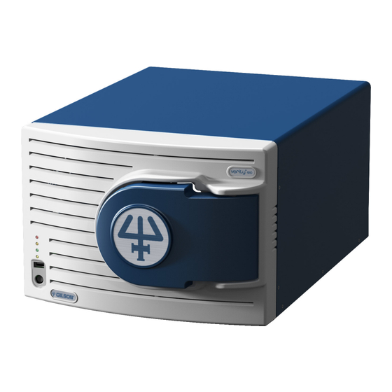
The ions introduced through the vac-chip are then focused using a series of electrostatic ion optics. The ionchip filters the ions according to their mass-to-charge (m/z) ratios and directs them to the detection system. Software controls the settings of the VERITY 1910 MS Detector and related instruments. Figure 1 VERITY® 1910 MS Detector... - Page 11 MiDas™ to the VERITY 1910 MS Detector. Gilson recommends using a flow rate range of 10 µL–2 mL/min. The SFI is also used for auto tuning or calibrating the VERITY 1910 MS Detector. Refer to Chapter 3 | Auto Tune (Calibrate).
-
Page 12: Inspect Shipment
The vac-chip interface is pumped by an additional small diaphragm pump. All of the vacuum pumps are integrated internally in the VERITY 1910 MS Detector so there are no external, floor-standing pumps. This significantly reduces equipment noise, footprint, and size. -
Page 13: Technical Specifications
Flow Rate Range 0.3–2000 µL/min Interface Off-axis vac-chip™ microengineered atmospheric pressure interface Ionization Modes Positive and negative ESI modes Ion Source Spraychip® electrospray ionization source VERITY 1910 MS DETECTOR TECHNICAL SPECIFICATIONS (CONTINUED ON PAGE 14) VERITY® 1910 MS DETEcToR | USER’S GUIDE... - Page 14 10 pg of reserpine yields a peak in SIM mode with a S/N ratio of 10:1 (RMS) PC control via Ethernet and TRILUTION® LC Software Software Control Control via Ethernet and Gilson Glider Prep (GGP) Software and Masscape® Software Weight 32 kg (70.5 lbs.) InTRoDUcTIon VERITY®...
-
Page 15: Installation
chapter 2 INStaLLatION Chapter 2 | IN thIS Chapter ● Setup ● Stacking ● vac‑chip™ Installation ● spraychip® Installation ● Rear Panel connections ● Front Panel VERITY® 1910 MS DETEcToR | USER’S GUIDE... -
Page 16: Setup
HPLC etc. The VERITY 1910 MS Detector is too heavy to be lifted or moved by one person safely. To avoid personal injury and for general safety, if moving or lifting the CAUTION VERITY 1910 MS Detector, always have another person assist you. -
Page 17: Stacking
The VERITY® 1910 MS Detector must be installed on a lab bench. The MiDas™ can be stacked on top of the VERITY 1910 MS Detector. connect the drain tube to the outlet on the gutter provided with the MiDas. Place the front feet of the MiDas through the holes in the gutter. -
Page 18: Vac-Chip™ Installation
The vac‑chip assembly houses the vac‑chip and the tube lens assembly (Figure 5). The vac‑chip assembly will be fitted and removed from the VERITY 1910 MS Detector as part of routine customer maintenance procedures whenever the vac‑chip needs to be cleaned or replaced. - Page 19 7. Use a Phillips screwdriver to partially unscrew the five vacuum screws in the following pattern: 1, 4, 2, 5, 3 (Figure 6). Repeat until the screws are loose. Figure 6 Tube Lens Assembly and Vacuum Screws 8. Gently lift the tube lens assembly away from the vac‑chip flange. 9.
- Page 20 Do not over tighten the vacuum screws, and do not continue to tighten screws if any NOTICE resistance is felt, in this case remove the assembly and retry. The vacuum screws have been specially made for the VERITY 1910 MS Detector. Do not CAUTION substitute these screws unless they have been provided by Gilson.
-
Page 21: Spraychip® Installation
spraychip® Installation 1. carefully screw the spraychip into the split flow interface (SFI). NOTICE Do not use a tool and do not overtighten the spraychip. Main Tubing Body Metal connections collar PEEK Screw spraychip Grub Screw Figure 9 The spraychip® and Split Flow Interface (SFI) 2. - Page 22 If there is resistance when tightening the screw, stop and repeat steps 3–5. 6. connect the high voltage connector from the SFI to the high voltage output located at the front of the VERITY 1910 MS Detector (Figure 11). High...
- Page 23 Split Flow Interface (SFI) Orientations The split flow interface (SFI) can be fitted to the VERITY 1910 MS Detector in two orientations, shown in Figure 13. The functions of the two tubing connections on the main body are not interchangeable. They are used as the liquid input line and as the waste line of the split.
-
Page 24: Rear Panel Connections
Rear Panel Connections The connections and ports on the rear panel of the VERITY 1910 MS Detector are shown below. These ports include terminals and connectors for the gas supply, vacuum exhaust system, and Pc peripherals. USB B-Type Connector r MiDas™... - Page 25 Power Connections pOWer SUppLY The power supply in the VERITY 1910 MS Detector accepts any line voltage in the range 100–240V. There is no voltage selector or externally accessible fuses on the VERITY 1910 MS Detector. Refer to Rear Panel Connections on page 24.
- Page 26 COrD CONNeCtION locate the appropriate power cord for your line voltage, connect the power cord to the power socket on the VERITY 1910 MS Detector and then to a grounded power outlet. Do not power on the instrument until directed.
- Page 27 5. Ensure that the VERITY 1910 MS Detector is powered off. 6. locate the Ethernet cable provided with the VERITY 1910 MS Detector. 7. connect an Ethernet cable into one of the ports (G) and the other end to the router.
- Page 28 Rear Panel Connections on page 24 for the location of all ports and connected cables. If the VERITY 1910 MS Detector is not contained in a vented hood, connect a suitable length of 8 mm tubing from the pump exhaust (n) to the laboratory’s exhaust system.
-
Page 29: Front Panel
Front Panel Refer to the diagrams below for the connections, ports, and indicator lights on the front panel of the VERITY 1910 MS Detector. Figure 14 Front Panel Connections for the VERITY® 1910 MS Detector (Door Closed) Figure 15 Front Panel Connections for the VERITY®... - Page 30 USB device can be connected to the front or rear panel of the MS detector. Power Button The power button is used to power the VERITY 1910 MS Detector on or off once the power switch on the rear panel of the MS detector has been switched on.
- Page 31 1. Make the plumbing connections between the lc system, VERITY 1910 MS Detector, and the MiDas. Refer to Plumbing Diagrams on page 32. ● If using the standard Gilson split ratio proceed to step 2, but if a custom split ratio is desired proceed to step 3.
- Page 32 pLUMBING DIaGraMS Refer to the diagrams below and the tables that follow when making front panel plumbing connections. Waste Figure 17 Front Panel Connections InSTallaTIon VERITY® 1910 MS DETEcToR...
- Page 33 Front Panel Tubing connection Tubing Fitting Input Destination 1/16" OD PEEK Coned 10‑32 PEEK Splitter Column 1/16” OD Coned 10‑32 PEEK Splitter UV/VIS 0.040” ID PEEK* 4‑Way Tee, Coned 10‑32 PEEK Splitter 0.002" ID Bore 1/16" OD 3‑Way Tee, Coned 10‑32 PEEK Splitter 0.005"...
- Page 34 Front Panel Components Coned 10‑32 PEEK Inline Microfilter 4‑Way Tee Backpressure Regulator, 100 psi Backpressure Regulator, 750 psi 3‑Way Tee 1/4–28 Flangeless Fitting Pump Head Inlet Power Button Coned 6/32 PEEK 1/8" Tefzel InSTallaTIon VERITY® 1910 MS DETEcToR...
-
Page 35: Auto Tune (Calibrate)
VERITY® 1910 MS Detector has been moved to a new environment. Sodium trifluoroacetate (NaTFA) is used to calibrate the VERITY 1910 MS Detector. The required solution is 10 mmol in 1:1 2-propanol:water. VERITY® 1910 MS DETEcToR... -
Page 36: Locate Required Items
1. Start the pump down. Nitrogen gas purges the interface before the vacuum pumps are activated. Other commands to the VERITY 1910 MS Detector are not allowed during the pump down cycle. It takes NOTE approximately five minutes for the vacuum pumps to reach the necessary speeds to complete the pump down. -
Page 37: Prepare The Syringe Pump
4. Install the plug (part number 49041124) into the waste line port of the SFI. It is important to strictly follow all safety instructions included with the syringe pump. If the VERITY 1910 MS Detector is installed as a constituent part of another system, the WARNING safety of the assembled system is the responsibility of the person responsible for that systems assembly. -
Page 38: Plumb The Syringe Pump
Plumb the Syringe Pump 1. complete the required fluidic connections and tubing to the syringe. Do not connect the syringe pump tubing (11) to the microfilter tubing (10) attached to the split flow interface (SFI). Refer to Figure 18. Figure 18 Plumbing Connections between the Syringe Pump and Split Flow Interface (SFI) Syringe Pump Tubing connection... -
Page 39: Run The Auto Tune (Calibration) Procedure
Troubleshooting Table on page 72. Flush the System Gilson recommends flushing the system after the Auto Tune (calibration) procedure is complete to remove any traces of the calibration solution. Follow the procedures below to flush the SFI and spraychip to remove any trace of the calibration solution. -
Page 41: Operation
chapter 4 OperatION Chapter 4 | IN thIS Chapter ● Prepare to Analyze ● Safety Interlock ● Power on ● Pump Down ● Power Down VERITY® 1910 MS DETEcToR | USER’S GUIDE... -
Page 42: Prepare To Analyze
WARNING laboratory exhaust system or have a silencer fitted. Removal of the top cover of the VERITY 1910 MS Detector can lead to the risk of personal injury and exposure to hazardous voltages. Never remove the cover of the VERITY 1910 MS Detector, only certified persons are authorized to carry out repairs internally. -
Page 43: Safety Interlock
Safety Interlock The VERITY 1910 MS Detector has a safety interlock system to protect users from high voltages. This system is operated by the door in the front cover. The door has two positions as shown in Figure 19. When the door is closed, the safety interlock is off and high voltages can be applied. When the door is fully closed it should be pushed gently forward until the catch engages with the front cover. -
Page 44: Power On
2. Set the power switch at the rear of the unit to ON. Refer to Rear Panel Connections on page 24. 3. Press the power button on the front panel to switch the VERITY 1910 MS Detector on. Refer to Front Panel on page 29. -
Page 45: Power Down
Power Down The following section details the basic procedures for putting the VERITY 1910 MS Detector into standby mode, venting the VERITY 1910 MS Detector, and powering down the VERITY 1910 MS Detector. Standby The VERITY 1910 MS Detector must be put into standby before performing certain maintenance tasks or venting the VERITY 1910 MS Detector. -
Page 47: Maintenance
chapter 5 MaINteNaNCe Chapter 5 | IN thIS Chapter ● Maintenance Schedule ● General Maintenance ● Vac-chip Assembly ● Vac-chip ● Spraychip ● Spraychip Flange ● Source, Filter, and Detector (SFD) Assembly ● Liquid Flow Rate Measurement ● Split Flow Interface VERITY®... -
Page 48: Maintenance Schedule
If in doubt, power down the instrument and perform the maintenance with the instrument disconnected from the power outlet. Refer to Power Down on page 45. The external surfaces of the VERITY 1910 MS Detector can be cleaned by wiping the surfaces down with 10% aqueous isopropyl alcohol. - Page 49 Cleaning Guidelines The items used with the VERITY 1910 MS Detector that can be maintained by the user are the spraychip®, vac-chip™ and split flow interface (SFI). All items can be cleaned and/or replaced by the user. The following warning notices apply to all cleaning procedures detailed in this chapter.
-
Page 50: Vac-Chip™ Assembly
1. Turn off any sample or mobile phase pumps, including the MiDas, to stop all flow to the spraychip. ● If the VERITY 1910 MS Detector is under vacuum, make sure that the instrument is not collecting data. 2. Place the VERITY 1910 MS Detector into standby mode, if necessary. - Page 51 10. Lay the assembly face down on a clean lint-free surface. ● The tube lens assembly is attached to the vac-chip vac-chip flange with five vacuum Screws screws. The vac-chip is located under this assembly. 11. Use a Phillips screwdriver to partially unscrew the five Tube vacuum screws in the following...
- Page 52 Clean the vac‑chip Flange The following procedure is the recommended cleaning procedure for your vac-chip flange. The vacuum screws have been specially made for the VERITY 1910 MS Detector. Do not substitute these screws unless they have been provided by Gilson.
- Page 53 ● If the vac-chip looks visually degraded or you have any questions, please contact Gilson before using the vac-chip. Refer to Customer Service on page 12. VERITY® 1910 MS DETEcToR...
- Page 54 Do not over tighten the vacuum screws and do not continue to tighten screws if any NOTICE resistance is felt, but rather remove the assembly and retry. The vacuum screws have been specially made for the VERITY 1910 MS Detector. Do not CAUTION substitute these screws unless they have been provided by Gilson.
-
Page 55: Spraychip
Replace the spraychip when the sensitivity for the VERITY 1910 MS Detector drops below acceptable levels. Use the following procedures to remove and install the spraychip into the main body of the SFI: Remove the spraychip 1. Put the VERITY 1910 MS Detector into standby mode, if necessary. - Page 56 6. Unscrew the grub screw to unfasten the spraychip from the assembly (Figure 25). Main Tubing Body connections Metal collar PEEK Screw Spraychip Grub Screw Figure 25 The Split Flow Interface (SFI) 7. carefully unscrew and remove the spraychip from the SFI. MAInTEnAncE VERITY®...
- Page 57 4–6. 7. connect the high voltage connector from the SFI to the high voltage output located at the front of the VERITY 1910 MS Detector (Figure 24). 8. close the door on the front cover. Ensure the PEEK tubing lines from the SFI are fed through the cutouts in the door NOTICE (Figure 24).
- Page 58 Using the split flow interface (SFI) is the recommended option; however, it is not possible to run the VERITY 1910 MS Detector during this cleaning procedure. The other option (Using the Reducing Union on page 59) allows for running the VERITY 1910 MS Detector while cleaning the spraychip.
- Page 59 CAUTION Do not mount the SFI to the VERITY 1910 MS Detector during this process. 5. Infuse at least 150 µL of the water/methanol using a flow rate of 10 µL/min. The solution will flood the spraychip during this process.
-
Page 60: Spraychip Flange
Spraychip Flange The spraychip flange is used to connect the microspray source of the VERITY 1910 MS Detector to the source, filter, and detector assembly (SFD) and provides access to the nebulizer gas connection. The spraychip and vac-chip flanges, once assembled together, generally remain so unless extensive cleaning is required. -
Page 61: Source, Filter, And Detector (Sfd) Assembly
The SFD assembly can only be assembled and fitted to the VERITY 1910 MS Detector by trained personnel. When fitted, the SFD assembly creates two chambers: the analytical chamber (housing the ionchip and detector) and the ion guide chamber (housing the ion guide). -
Page 62: Liquid Flow Rate Measurement
Liquid Flow Rate Measurement In the case that sensitivity or spray stability remains poor after cleaning or replacement of the spraychip, it is recommended the liquid flow rate through the spraychip assembly is measured. This can be performed on the split flow interface (SFI). To measure the liquid flow rate, the flow meter assembly (Figure 32) will be required. - Page 63 4. Turn on the pump. NOTE Flow rates should only be measured with the flow meter tube in a horizontal position. 5. Start a timer when the liquid meniscus reaches the first visible graduation on the flow meter tube. 6. Measure the time taken for the liquid meniscus to travel over a number of graduations. 7.
-
Page 64: Split Flow Interface
WARNING Remove the Split Flow Interface 1. Ensure the VERITY 1910 MS Detector is in standby mode and the nitrogen flush is active. 2. open the door on the front cover. NOTICE Feed the PEEK tubing through the cutouts when opening or closing the door. - Page 65 1. Fill a syringe with a 50:50 (v/v) mixture of HPLc-grade methanol and water with no additives and mount in a syringe pump. 2. If fitted, remove the SFI from the VERITY 1910 MS Detector (Remove the Split Flow Interface on page 64) and remove the spraychip (Remove the spraychip on page 55).
- Page 66 Install the Split Flow Interface 1. Ensure the VERITY 1910 MS Detector is in standby mode and the nitrogen flush is active. 2. Ensure the door is open at 90°. 3. Align the split flow interface (SFI)—with installed spraychip—with the opening in the vac-chip assembly.
- Page 67 Replace the Split Flow Interface Tubing When the split flow interface (SFI) appears blocked and/or the measured flow rates are incorrect, then the low flow tubing should be replaced. The following sections detail the procedures for replacing the tubing in the SFI assembly. The SFI tubing kit (part number 14410014) will be required for the following sections.
- Page 68 6. Use a PH1 Phillips screwdriver to loosen (but not remove) the three screws in the main body of the SFI. When the screws are loose, remove the top cover of the SFI (Figure 38). Securing Screws Input Line nut Top cover Reducing Union...
- Page 69 20. Fit either a spraychip or measure the flow rate (Liquid Flow Rate Measurement on page 62). ● If the initial problem persists and/or you have any queries please contact Gilson. Refer to Customer Service on page 12.
-
Page 71: Troubleshooting
● Repair and Return Policies This chapter provides information on what to do in the unlikely event that you experience difficulty with the VERITY® 1910 MS Detector. If problems persist, contact your local Gilson representative. Refer to Customer Service on page 12. -
Page 72: General Warnings
General Warnings Before troubleshooting, ensure that the VERITY 1910 MS Detector is switched off, unless WARNING otherwise stated. CAUTION Always wear eye protection and use suitable tools when handling capillaries. Troubleshooting Table The following table details some basic symptoms, possible causes, and potential solutions for some basic issues with the VERITY 1910 MS Detector. - Page 73 System is not calibrated or Follow the procedure to calibrate the Ions are in the wrong m/z auto tuned, or has lost its VERITY 1910 MS Detector. Refer to position calibration. Chapter 3 | Auto Tune (Calibrate). Contact Gilson. Refer to O-rings may be leaking.
-
Page 74: Repair And Return Policies
Repair and Return Policies Before Calling Us Your local Gilson representative will be able to serve you more efficiently if you have the following information: ● Serial number and model number of the instruments involved ○ The serial number is located on the rear panel ●... -
Page 75: Flow Splitting
Appendix A FLOW SpLiTTinG Appendix A | in THiS CHApTeR ● overview ● Equations ● Split Ratios VERITY® 1910 MS DETEcToR | USER’S GUIDE... -
Page 76: Overview
Overview In its simplest form, a flow splitter is composed of a union or tee with tubing of various inner diameters attached as shown in Figure 41. This appendix describes how to calculate the theoretical flow rates from a ratio of tube lengths and diameters. -
Page 77: Equations
Equations The split ratio (R) is the ratio of the flow rates exiting the high flow tube and the low flow tube. This is dependent on a number of factors including the properties of the fluid, e.g., viscosity. However, the following equations can be used to calculate the split ratio for the VERITY®... - Page 78 Equation 3 ● Equation 3 can be used to estimate the length of the high flow tube that is required. For example, if an Hplc method uses a flow of 1.0 ml/min, using “Equation 2” to achieve a flow rate of 1 µl/min in the spraychip (low flow tube): For the SFI the following is constant: Using Equation 1: If the inner diameter of your desired waste tube is 254 µm:...
-
Page 79: Split Ratios
The theoretical calculations provided in this manual cannot be used for such systems. once established, measure the flow rates of different gradient compositions to establish any variations in flow. Gilson, Inc. recommends that the flow rate throughout the gradient should be 0.3–2 µl/min. VERITY® 1910 MS DETEcToR... -
Page 81: Appendix Bauxiliary I/O
Appendix B AUxiLiARY i/O Appendix B | in THiS CHApTeR ● overview ● Auxiliary I/o Port Pin Assignments ● Triggering Sources ● Analog Inputs and outputs VERITY® 1910 MS DETEcToR | USER’S GUIDE... -
Page 82: Overview
Warnings Any external instrument sending/receiving triggers and/or analog voltages to the VERITY 1910 MS Detector should not exceed the input/output values stated here. Gilson is not responsible for any damage to external instrumentation from improper connections made to the VERITY 1910 MS Detector. -
Page 83: Auxiliary I/O Port Pin Assignments
EMC regulations. WARNING Use of any cabling not supplied or recommended by Gilson may lead to the risk of electric shock or short circuit. WARNING VERITY® 1910 MS DETEcToR... -
Page 84: Triggering Sources
The following tables give example trigger wiring connections for use if you have been supplied with an open ended cable, examples include triggering from active and passive sources. All terminations not made to the VERITY 1910 MS Detector should be made in accordance with the relevant manufacturer’s instructions. - Page 85 Figure 43 Sample Wiring for a Passive Source If attaching the VERITY 1910 MS Detector to a passive trigger source the user must ensure NOTICE the external instrument is rated for the output from the VERITY 1910 MS Detector. Gilson is not responsible for any damage to external instrumentation.
-
Page 86: Analog Inputs And Outputs
The following tables give example analog input and output connections for use if you have been supplied with an open ended cable. All terminations not made to the VERITY 1910 MS Detector should be made in accordance with the relevant manufacturer’s instructions. -
Page 87: Appendix C | Parts And Accessories
THiS CHApTeR ● System ● components All items listed must only be supplied by Gilson or an agent thereof. Use of alternative parts CAUTION may lead to improper operation of the VERITY 1910 MS Detector or failure to comply with safety or EMC regulations. -
Page 88: System
System Part number Description 14410031 VERITY 1910 MS DETECTOR, MIDAS FOR TRILUTION LC 14410032 VERITY 1910 MS DETECTOR, MIDAS FOR PLC 14410028 VERITY 1910 MS DETECTOR, FOR TRILUTION LC 14410029 VERITY 1910 MS DETECTOR, FOR PLC 14410030 MIDAS, SPLITTER MAKE UP PUMP FOR MS... - Page 89 Calibration Kit Part number Description 14410023 VERITY 19X0 MS CALIBRATION KIT 14410018 PLUMBING PKG,VERITY 19X0 CALIBRATION Split Flow Interface Part number Description 14410015 VERITY 19X0 SPLIT FLOW INTERFACE (SFI) 14410016 VERITY 19X0 SPLIT FLOW REBUILD KIT 14410014 VERITY 19X0 TUBING KIT 14417007 VERITY 19X0 1/32 PEEK SFI FERRULE Miscellaneous...
- Page 92 LT309179-02...
Need help?
Do you have a question about the VERITY 1910 MS and is the answer not in the manual?
Questions and answers