Table of Contents
Advertisement
Quick Links
Advertisement
Table of Contents

Related Manuals for Gilson VERITY 1741


Summary of Contents for Gilson VERITY 1741
- Page 1 User’s Guide VERITY® 1741 UV-VIS Detector...
- Page 3 Trademarks All product and company names are trademarks™ or registered® trademarks of their respective holders. Use of the trademark(s) in this document does not imply any affiliation with or endorsements by the trademark holder(s).
-
Page 5: Table Of Contents
TABLE OF CONTENTS SAFETY General operating Instructions Symbols and Signs Safety Notices chemical Hazards Adherence to Laboratory Regulations Voltage Replacement Parts INTRODUCTION cHAPTER 1 | Description Unpacking Technical Specifications customer Service Unpacking Technical Specifications customer Service INSTALLATION cHAPTER 2 | Test cell Removal Flow cell Installation Plumbing connections... - Page 6 Flow cell Replacement TROUBLESHOOTING cHAPTER 5 | Troubleshooting Repair and Return Policies PARTS AND ACCESSORIES APPENDIX A | VERITY 1741 Detector and Shelf Accessory Lamps Miscellaneous Flow cells/Tubing/Fittings FRONT PANEL CONTROL APPENDIX B | Description of Symbols on the Screen...
-
Page 7: Safety
The VERITY® 1741 UV-VIS Detector is intended to be used in a laboratory environment by trained technical personnel. VERITY 1741 Detector control is via Ethernet and TRILUTIoN® Lc Software or via the front panel. VERITY® 1741 UV-VIS DETEcToR | USER’S GUIDE... -
Page 8: General Operating Instructions
General Operating Instructions The detector may not be used if it is leaking. Do not place detector or any other equipment so that disconnecting power cord is difficult. Never manipulate with the detector if the door is mounted. There is a danger of its damage. UV light is dangerous for eyes. -
Page 9: Chemical Hazards
Be sure to use only replacement parts mentioned in this user’s guide. Do not repair or change parts which are not listed in this user’s guide. If it is necessary to change parts not listed, please contact your Gilson-authorized representative. SAFETY... - Page 10 This page intentionally left blank...
-
Page 11: Introduction
The VERITY® 1741 UV-VIS Detector is for use in semi-preparative to preparative high performance liquid chromatography (HPLc) purification systems and provides multiple-wavelength scanning detection from 200–800 nm. The VERITY 1741 Detector is controlled via its front panel or TRILUTIoN® Lc Software as a component in an HPLc system. Multiple, different wavelengths can be used to simultaneously trigger fraction collection. -
Page 12: Description
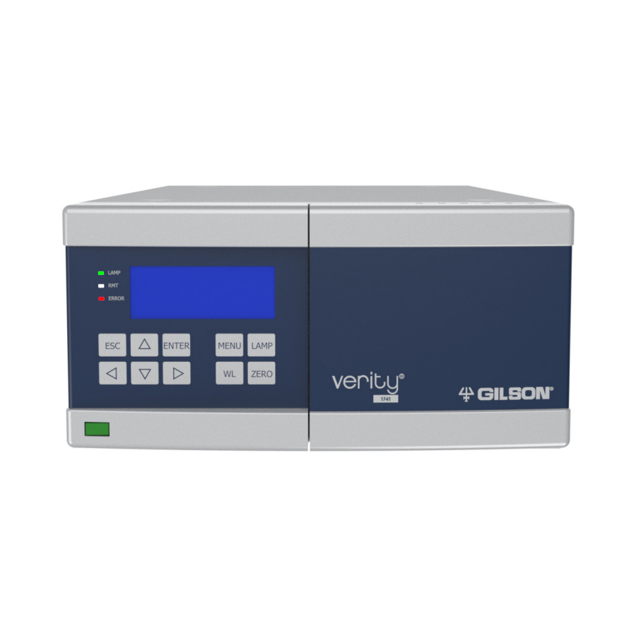
Description The images in this section show the main components of the VERITY 1741 Detector. Front View To prevent damage during shipping, the detector is shipped with the door removed. Figure 1 VERITY® 1741 UV-VIS Detector - Front View (Door Removed) - Page 13 Side View Figure 2 VERITY® 1741 UV-VIS Detector - Side View DESCRIPTION Light sources are under a small cover. Remove the cover when replacing the lamp(s). Rear View Figure 3 VERITY® 1741 UV-VIS Detector - Rear View DESCRIPTION Power switch, fuse drawer, and power receptacle Connector Ethernet/LAN Connector IO INTERFACE Analog outputs A, B, C, D...
-
Page 14: Unpacking
Appendix A | Parts and Accessories on page 33 for part numbers. Optional Accessory SheLF An optional stacking shelf that was designed for use with the VERITY 1741 Detector is ordered separately (part number 21040255). It allows for stacking a pump on top of the detector. INTRoDUcTIoN... -
Page 15: Technical Specifications
Technical Specifications SPECIFICATION DEFINITION OR VALUE Communication Interface LAN (Ethernet) Control Front panel control or computer control via Ethernet and TRILUTION® LC Software Wavelength Range 200–800 nm (256 CCD elements) Wavelength Accuracy ± 1 nm Wavelength Reproducibility ± 0.5 nm Noise ±... -
Page 16: Customer Service
If you need assistance, please contact your local Gilson representative. Specific contact information can be found at www.gilson.com. To help us serve you quickly and efficiently, please refer to Before Calling Us on page 32. -
Page 17: Installation
chapter 2 INStaLLatION Chapter 2 | IN thIS Chapter: ● Test cell Removal ● Flow cell Installation ● Plumbing connections ● Door Installation ● Waste Tubing Assembly Installation ● Rear Panel connections Place the detector in a suitable location that satisfies the following conditions: ●... -
Page 18: Test Cell Removal
Test Cell Removal Figure 5 Test Cell Figure 4 Front View with Door Removed The detector is shipped from the factory with the door removed and a test cell installed, which does not have connections for solvent. Before using the detector with solvents, the test cell must be removed and a flow cell must be installed. -
Page 19: Plumbing Connections
Plumbing Connections This section describes how to make inlet and outlet tubing connections and uses tubing and fittings supplied with the flow cell. The 1/8" flow cells are supplied with FEP tubing oD 1/8” and the 1/16" flow cells are supplied with PEEK tubing oD 1/16”. Inlet/Outlet Tubing Preparation cut the supplied tubing into two pieces. - Page 20 Outlet Tubing Connection 1. Put the fitting(s) supplied with the flow cell on one end of the other piece of the cut tubing. Use only nuts and ferrules made of PEEK or KEL-F. ● For 1/16" flow cells, put a PEEK one-piece nut on one end of the tubing. ●...
-
Page 21: Door Installation
Door Installation To prevent damage during shipping, the detector is shipped with the door removed. Slip the door on the hinges in the open position (see pictures below). Waste Tubing Assembly Installation The detector is equipped with a waste channel, directing the liquid away from the detector. The supplied waste tubing assembly includes silicone tubing and the necessary connectors. -
Page 22: Rear Panel Connections
Rear Panel Connections Refer to the diagram below when making the connections described in this section. Figure 12 VERITY® 1741 UV-VIS Detector - Rear View DESCRIPTION Combined power socket with main switch and main fuse Connector Ethernet/LAN Connector IO INTERFACE Analog outputs A, B, C, D Ethernet To make the Ethernet connection to the instrument, a router and... - Page 23 Input/Output Connections The VERITY 1741 Detector has an interface for connection to external devices. The interface has two universal inputs (DIn1 and DIn2) and two universal outputs (DoUT1 and DoUT2). If input/output connections will be used, locate the terminal block connector provided with the detector and make the connection to the port labeled InTERFAcE.
- Page 24 This page intentionally left blank...
-
Page 25: Chapter 3 | Operation
● Start Up ● Turn Lamp on TRILUTIoN® Lc Software provides software control of the VERITY 1741 Detector for setup and operation of the detector in a chromatographic run. Instructions for controlling the VERITY® 1741 UV-VIS Detector using TRILUTIoN Lc are provided on the documentation USB supplied with the detector. -
Page 26: Front Panel
6. If using front panel control, press the laMp key to turn on the lamps. For instructions about using the front panel control, refer to Appendix B | Front Panel Control on page 37. NOTE When the VERITY 1741 Detector is under TRILUTION LC control, the front panel keypad is locked. oPERaTIoN VERITY® 1741 UV-VIS DETEcToR... -
Page 27: Turn Lamp On
Turn Lamp On To use TRILUTIoN Lc to turn the lamp(s) on: NOTE The detector requires a 15–30 minute warm-up period to achieve a stable baseline. 1. create a TRILUTIoN Lc method with the detector in the configuration. a. Select Scan. The software searches for the detector. b. - Page 28 This page intentionally left blank...
-
Page 29: Maintenance
chapter 4 MaINteNaNCe Chapter 4 | IN thIS Chapter: ● Lamp Replacement ● Intensity calibration after Lamp(s) Replacement ● Fuse Replacement ● cleaning and Decontamination ● Flow cell Replacement VERITY® 1741 UV-VIS DETEcToR | USER’S GUIDE... -
Page 30: Lamp Replacement
Lamp Replacement It is recommended to replace both the deuterium lamp and tungsten lamp at the same time. When replacing the lamps, replace both lamps first and then calibrate the lamp intensity. NOTE If replacing ONLY the tungsten lamp, then do NOT perform the lamp intensity calibration. Deuterium Lamp Replacement This operation may be performed only by a qualified person. - Page 31 5. Loosen and remove the two screws on the lamp socket. 6. Remove the lamp from the lamp socket. 7. Insert the new lamp. construction of the lamp case allows only one correct position—it is impossible to insert the lamp incorrectly. Proper placement is ensured by a groove on the lamp case, leading toward the rear panel of the detector.
- Page 32 Tungsten Lamp Replacement This operation may be performed only by a qualified person. Before replacing a lamp, always unplug the detector from power source by disconnecting main supply cable. Reconnect the detector to the power source only after the cover is mounted back in place. UV light is dangerous for your eyes.
- Page 33 INStrUCtIONS 1. Disconnect the detector from the power source. 2. Unscrew the four screws and then remove the small cover on the side of the detector. 3. Disconnect the connectors; pull away the lamp conductors from the instrument. Never touch the quartz bulb with bare fingers because fingerprints will irreversibly damage NOTICE the lamp after being switched on.
-
Page 34: Intensity Calibration After Lamp(S) Replacement
Intensity Calibration after Lamp(s) Replacement after changing the deuterium lamp, the lamp intensity should be calibrated. If replacing both the deuterium and tungsten lamps, replace both lamps before performing the intensity calibration. Follow the instructions below to calibrate the intensity. Refer to Service on page 52 for additional details. -
Page 35: Fuse Replacement
Fuse Replacement CAUTION Always disconnect the detector from the power source before replacing the line fuse. 1. Using a flat-tip screwdriver release the fuse holder from its bottom. 2. Take out the fuse holder. 3. Remove the old line fuse. 4. -
Page 36: Cleaning And Decontamination
If flushing did not help, contact your local Gilson representative. Flow Cell Replacement The flow cell compartment is located at the front of the detector, behind the closed door. -
Page 37: Chapter 5 | Troubleshooting
Contact your local Gilson Electronics/optic failure. representative. Try resetting of error and if is not Warning or error message successful contact your local Gilson representative. Check and replace flow cell inlet/ Clogged tubing. outlet tubing, if necessary. Leaking flow cell Damaged or worn flow cell. -
Page 38: Repair And Return Policies
Repair and Return Policies Before Calling Us Your local Gilson representative will be able to serve you more efficiently if you have the following information: ● the serial number and model number of the instruments involved. The serial number is located on the rear panel. -
Page 39: Appendix A | Parts And Accessories
PART DESCRIPTION NUMBER 14161003 VERITY 1741 UV-VIS DETECTOR 21040255 SHELF,VERITY 1741 Optional shelf for stacking a pump on top of the VERITY 1741 Detector in a system Lamps PART DESCRIPTION NUMBER 21040253 LAMP DEUTERIUM, PLCA, V2 Deuterium Lamp for VERITY 1741 Detector... -
Page 40: Miscellaneous
NUMBER 14161011 FLOW CELL,1.3MM,1/16,1741 Flow cell assembly with a 1.3 mm pathlength and 1/16" OD internal tubing for VERITY 1741 Detector 14161014 FLOW CELL,0.5MM,1/16,1741 Flow cell assembly with a 0.5 mm pathlength and 1/16" OD internal tubing for VERITY 1741 Detector 14161012 FLOW CELL,0.1MM,1/16,1741... - Page 41 NUMBER 14161015 FLOW CELL,1.3MM,1/8,1741 Flow cell assembly with a 1.3 mm pathlength and 1/8" OD internal tubing for VERITY 1741 Detector 14161018 FLOW CELL,0.5MM,1/8,1741 Flow cell assembly with a 0.5 mm pathlength and 1/8" OD internal tubing for VERITY 1741 Detector 14161016 FLOW CELL,0.1MM,1/8,1741...
- Page 42 This page intentionally left blank...
-
Page 43: Appendix B | Front Panel Control
● Preferences ● Io config ● Analog outputs ● Info ● Diagnostics ● Service The VERITY 1741 Detector includes a display and keypad for front panel control. Figure 17 VERITY® 1741 UV-VIS Detector - Front View DESCRIPTION Display Keypad VERITY® 1741 UV-VIS DETEcToR... -
Page 44: Description Of Symbols On The Screen
Description of Symbols on the Screen TC1s Time constant for signal filtering. BW8nm Electrical bandwidth for setting the range around a given wavelength. I0.0% Percentage of light intensity. A254 nm Wavelength set on channel A. +5175.58mAU Actual value of absorbance in mAU units. Current detector mode. -
Page 45: Operating Modes
Operating Modes The detector may be in different operating modes depending on the desired operation. The detector enters some modes by command of the operator or control computer, others are invoked automatically to perform a sequence of different operations. MODE DESCRIPTION ABBREVIATION START... - Page 46 After successful calibration, the main screen displays the absorbance measurement. MEASURE ABSoRBAncE (ABS) on channel A at the preset basic wavelength (254 nm). The wavelength now can be set for the displayed channel directly from this window, using the up and down arrows. During a wavelength change the detector signal is not automatically zeroed (Autozero).
-
Page 47: Working With The Menu
Working with the Menu The menu screen enables setting all parameters and functions of the detector, its diagnostics, and service. The main menu is accessed by pressing the MenU key. navigate the menu using the arrow keys, enTeR key, and eSC key. Press the MenU key to exit the current screen. Figure 18 Menu Flow Diagram Parameters... - Page 48 Time Constant The time constant represents the level of signal filtering. A preset value is used for both digital and analog outputs. A slower (longer) time constant value decreases the overall noise on the detector output, but also decreases the response speed (response delay– time lag) and changes the shape of peaks (they are wider and lower).
-
Page 49: Preferences
Math Math SETTING DESCRIPTION Selecting a function on the mathematic channel D (OFF; A+B; A-B; AVG; SUB/2; MAX; A/B; NEG A; ABS A). OFF: Math functions are disabled. A+B: The absorbance of channels A and B is added. A-B: The absorbance of channels A and B is subtracted. AVG: Average of absorbances of channels A and B. - Page 50 Sound Set the sound signals for the detector. All items are activated by default. Sound Settings Setting Description At each touch of a button, a short beep will sound when the key does not have any significance at KEYBOARD the moment, a mid-length beep for a value change and moving within a menu, and a longer beep for confirmation of a value change.
-
Page 51: Io Config
MEDIUM -0.3 AU HIGHER −0.7 AU IO Config The VERITY 1741 Detector has an interface for connection to external devices. The interface has two universal inputs (DIn1 and DIn2) and two universal outputs (DoUT1 and DoUT2). Interface INTERFACE SPECIFICATION ABBR. NAME DESCRIPTION Auxiliary supply +5V DC, maximum output current 50mA. - Page 52 NOTE Connector blocks are meant for cables with size up to 1.5 mm Diagnostics of the actual Io InTERFAcE status are accessed by pressing the MenU key and then diagnostics | interface. For digital inputs value oPEn (H) means opened input, high selecting level and cloSE (l) means closed input, low level.
- Page 53 diGiTAL OUTpUT SWiTCH (dOUT1 And dOUT2) Function setting for outputs DoUT 1 and DoUT 2 on external interface: SETTING OF ACTIONS ON DIGITAL OUTPUT SETTING DESCRIPTION No function. The output is possible to control by commands from PC. OVRs1 Level H, when the absorbance A is higher than THRESHOLD s1. OVRs2 Level H, when the absorbance A is higher than THRESHOLD s2.
-
Page 54: Analog Outputs
Analog Outputs The detector has four independent analog outputs with cinch connectors. on the rear panel of the detector they are marked as AnAloG oUT and letters A to D. Each of the analog outputs can be preset oFFSET in the range of preset values from −0.100 V to +0.500 V. - Page 55 Boards The printed circuits information of the main board, display module, communication module, and analog output module is displayed. MAin BOARd Bn - board name, HW - board version, FW - firmware version, Un - board identification number. diSpLAY MOdULe Bn - board name, HW - board version, FW - firmware version, Un - board identification number.
-
Page 56: Diagnostics
Diagnostics The detector diagnostics is displayed. Errors When a serious problem occurs, the display shows an e in the lower right corner with the number of errors in parenthesis. When this occurs, it is usually impossible to continue with measuring and the detector switches to IDlE mode. - Page 57 deUTeRiUM LAMp (d2) The following values are displayed: Current Values of D2 (Deuterium Lamp) Control NAME DESCRIPTION Voltage at the output of the current regulator behind the measuring resistor (approx. +72 V). Voltage at the output of the current regulator in front of the measuring resistor (approx. +82 V). Voltage at the anode of the lamp (approx.
-
Page 58: Service
Leakage Allows for viewing some real-time measured values for leakage sensor diagnostics. If the leakage sensor is not connected, the display will show MODE: SENSOR NOT CONNECTED and the voltages VlKR and VlKS will be out of range below. Leakage Screen SETTING DESCRIPTION VLKR... - Page 59 Parts Replacement deUTeRiUM LAMp (d2) Resets the deuterium lamp age time and sets a new index of time counter. TUnGSTen LAMp (W) Resets the tungsten lamp age time. Calibrations ABSORBAnCe Using this item, the absorption response can be slightly corrected. The absorbance coefficient is the multiplier of the basic calculated value.
- Page 60 Gilson, Inc. 3000 Parmenter Street | Middleton, WI 53562 | USA lT303129-02 www.gilson.com/contactus original Instructions...
Need help?
Do you have a question about the VERITY 1741 and is the answer not in the manual?
Questions and answers