
Related Manuals for WAGO I/O System 750/753


Summary of Contents for WAGO I/O System 750/753
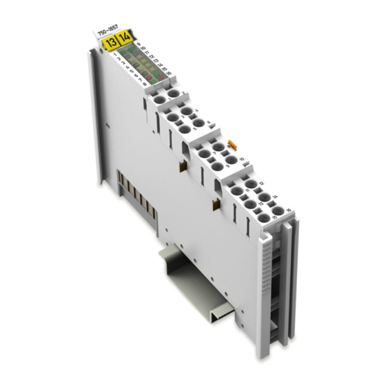
- Page 1 WAGO I/O System 750/753 4-Port IO-Link Master 750-1657 Product manual | Version 1.1.0 /WAGO/...
- Page 2 We wish to point out that the software and hardware terms as well as the trademarks of companies used and/or mentioned in the present manual are generally protected by trademark or patent. WAGO is a registered trademark of WAGO Verwaltungsgesellschaft mbH. Product manual | Version: 1.1.0 4-Port IO-Link Master...
-
Page 3: Table Of Contents
750-1657 Table of Contents Table of Contents 1 Provisions ........................ 6 Scope of Applicability .................... 6 2 Overview ........................... 7 3 Properties ......................... 8 View ......................... 8 Indicators ......................... 9 Wiring Interface ..................... 10 Power Jumper Contacts .................. 11 Circuit Diagram ...................... 12 4 Functions........................ - Page 4 Control / Status Byte .................. 60 8.2.2 Register Overview .................. 60 8.2.3 Example: Read Register 08 (WAGO Item Number) ........ 61 8.2.4 Example: Set Local Bus Process Data Width and Mailbox Length via Register 33........................ 62 IO-Link Master Tables ................... 62 8.3.1...
- Page 5 750-1657 Table of Contents 8.4.1.3 IO-Link Function Blocks .............. 80 8.4.1.4 Diagnostic Messages of the IO-Link Masters........ 81 8.4.2 PROFIBUS .................... 82 8.4.2.1 Process Image .................. 82 8.4.2.2 Configure with PROFIBUS GSD ............ 82 8.4.2.3 IO-Link Function Blocks .............. 89 8.4.2.4 Diagnostics when Using a PROFIBUS Fieldbus Coupler ....
-
Page 6: Provisions
The product must only be installed and operated in accordance with the complete operating instructions. Knowledge of all applicable documents is required for proper use. You can find all documents and information on the product detail page. Applicable document & System Manual I/O System 750/753 • Provisions • Safety • Planning •... -
Page 7: Overview
Function blocks, device descriptions or the WAGO IO-Link Configurator can be used to configure and parameterize the IO-Link master. The product can be operated on the head stations of the WAGO I/O System 750/753 indi- cated in section 8 Compatibility [} 25]. -
Page 8: Properties
8 Scope of Applicability [} 6] Marking possibility with Mini-WSB (op- tional) Indicators 8 Indicators [} 9] 8 Diagnostics via Indicators [} 28] & System Manual I/O System 750/753 Data contacts & System Manual I/O System 750/753 Access to open the associated Push-in ® CAGE CLAMP connection ®... -
Page 9: Indicators
750-1657 Properties 3.2 Indicators One- and two-color LEDs provide information about the operating status of the individual IO-Link ports. Figure 2: Indicators Channel LED Designation Operating status of C/Q 1 Operating status of C/Q 2 3 … 7 Reserved Operating status of IO-Link master Operating status of C/Q 3 Operating status of C/Q 4... -
Page 10: Wiring Interface
Properties 750-1657 3.3 Wiring Interface Figure 3: Wiring Interface Channel Designation Connection Function C/Q 1 IO-Link Port 1 Supply voltage 24 VDC L1− Supply voltage 0 V +24 V Field supply 24 VDC 0 V Field supply 0 V C/Q 2 IO-Link Port 2 Supply voltage 24 VDC L2−... -
Page 11: Power Jumper Contacts
750-1657 Properties 3.4 Power Jumper Contacts The potential for the field supply is fed in via the blade contacts and passed on via the spring contacts. For additional information on the Power Jumper Contacts, please see & System Manual I/O System 750/753. -
Page 12: Circuit Diagram
Properties 750-1657 3.5 Circuit Diagram Figure 5: Circuit Diagram & System Manual I/O System For information on the system power supply, please see 750/753. Product manual | Version: 1.1.0 4-Port IO-Link Master... -
Page 13: Functions
This allows IO-Link devices to be integrated in common automation systems and network structures independent of the bus systems used. The WAGO IO-Link Master complies with IO-Link Specification V.1.1.3. The “IO-Link” trademark is managed there under the term “Single-Drop Digital Communication Interface for Small Sensors and Actuators”... -
Page 14: Operational Functions
Functions 750-1657 4.1 Operational Functions 4.1.1 Operating Modes The IO-Link device ports of the 4-port IO-Link Master each support four operating modes: • IO-Link • DI (“Digital Input,” default setting) • DO (“Digital Output”) • Inactive 4.1.2 Parameter Description The parameters of the 4-Port IO-Link Master are mapped to an IO-Link-specific data model. -
Page 15: Process Image
750-1657 Functions Transmission is based on 24V levels and takes place in half-duplex mode, i.e., data is ei- ther sent or received. Standard sensor cables can be used. Shielding is not required. 4.3 Process Image The process image size of the IO-Link master can be adjusted to the number of devices (switches, IO-Link-compatible devices, etc.) connected to the IO-Link ports. - Page 16 Functions 750-1657 PI Size Input Output … … … … D43 Data byte 43 D43 Data byte 43 Product manual | Version: 1.1.0 4-Port IO-Link Master...
-
Page 17: Mailbox 2.0
750-1657 Functions 4.3.1 Mailbox 2.0 I/O modules with Mailbox functionality have an acyclic communication channel (Mailbox) in the process image of the local bus. It is based on the “Mailbox 2.0” transmission method, hereinafter referred to as “Mailbox”. If the Mailbox is enabled (control byte, bit 7 = 0), it is used as needed to transfer configu- ration, parameterization and diagnostic data. -
Page 18: Cyclic Process Data
Functions 750-1657 Process data that exceeds 1 bit per port is in the range of the cyclic data (see 8 Cyclic Process Data [} 18]). 4.3.3 Cyclic Process Data The following is an example of a Mailbox size of 2 bytes during configuration: The first 4 bytes of the input and output process image are occupied by the control or sta- tus byte, the Mailbox bytes and the SIO bytes. -
Page 19: Unfragmented Process Data
750-1657 Functions Figure 8: Local bus data width and segment size Note The process data width of the local bus and the Mailbox affect the size of the cyclic data! For example, if the Mailbox size is set to 2 bytes and the local bus process data width is set to 12 bytes or 8 bytes during configuration, the data area available for the cyclic data is reduced accordingly. -
Page 20: Figure 9 Example - Distribution Of Process Data In The Io-Link Master
Functions 750-1657 In addition to a set size of 2 bytes for the Mailbox, the following example shows a set size of 5 bytes for segment port 3. If the number of process data of an IO-Link device con- nected to port 3 does not correspond to the size of segment port 3, the effect of the ex- cess or missing area on the evaluation of the process data must be taken into account. -
Page 21: Fragmented Process Data
When fragmentation is switched on, the data is transferred in fragmented form for each port independently and in the corresponding port segment. WAGO controllers achieve the “fragmented process data” functionality by using the corre- 8 Compatibility sponding PLC library (see [} 25]). -
Page 22: Control And Status Bytes
Functions 750-1657 4.4 Control and Status Bytes The first byte of the local bus process image is reserved for the control byte (data direc- tion fieldbus coupler/controller -> IO-Link master) or status byte (data direction IO-Link master -> fieldbus coupler/controller). 8 Register The control byte is used to switch between register communication (see 8 Mailbox 2.0 Transmis-... -
Page 23: Local Bus Processing
Unless disabled, diagnostics of the connected IO-Link devices and those of the IO-Link Master itself are transferred to the controller via the “IOL_DIAG” diagnostic service (see 8 Diagnostic Telegram [} 29]) of the Mailbox to the controller. The WAGO-I/O-PRO li- brary “WagoLib_IO_Link.lib” provides the required function blocks to process the diag- nostic messages. - Page 24 Functions 750-1657 Therefore, a distinction is made between event codes generated by IO-Link master itself (see 8 Event Codes of the IO-Link Master [} 31]) and event codes generated by con- 8 Event Codes of Connected Devices nected devices (see [} 33]). Product manual | Version: 1.1.0 4-Port IO-Link Master...
-
Page 25: Planning
750-1657 Planning 5 Planning Note Read system manual! You can find cross-product information on the topic of Planning in the & System Manual I/O System 750/753. 5.1 Compatibility The I/O module is supported by the fieldbus couplers/controllers in the following table. The controllers require a PLC library for the corresponding runtime system: •... - Page 26 Planning 750-1657 Bus System Head Station Item no. Firmware Revision Status BA application controller 750-884 PFC100 fieldbus controller 750-81xx PFC200 fieldbus controller 750-82xx 750-82xx/040-00x ® DeviceNet Fieldbus coupler 750-306 ECO fieldbus coupler 750-346 Programmable Fieldbus Con- 750-806 troller ® CANopen Fieldbus coupler 750-337 750-338...
-
Page 27: Aids
Planning 5.2 Aids You can obtain the WAGO IO-Link Configurator software, as well as the associated prod- uct manual with a detailed description of the software, from ü www.wago.com. You can obtain the WAGO-I/O-PRO software, as well as the associated product manual with a detailed description of the software, from ü www.wago.com. -
Page 28: Diagnostics
Diagnostics 750-1657 6 Diagnostics 6.1 Diagnostics via Process Image If register communication is disabled (bit 7 in the control byte = 0), status information of the I/O module and IO-Link ports is displayed via the status byte. 8 Control and Status The description of the control and status bytes is available in Bytes [} 22]. -
Page 29: Diagnostics Via Expert Interface
750-1657 Diagnostics Table 9: LED 8 (operating status of IO-Link master) LED State Explanation Parameterization disabled Green flashing Parameterization enabled Table 10: LED 9 (operating status of C/Q 3) LED State Explanation Port disabled DI, DO: low state Green IO-Link: Device connected, IO-Link data OK DI, DO: high state Green flashing Startup or parameterization, duration ≥... -
Page 30: Table 15 Diagnostic Telegram - Legend
Diagnostics 750-1657 Table 15: Diagnostic Telegram – Legend Content Description Service ID 0x00 Cancel_DiagMsg_Request 0x01 Idle_Request 0x02 Send_DiagMsg_Request [0x03...0xFF] Reserved Sequence ID [0x00...0xFF] Used to distinguish between successive responses and associate with requests. Event Code 0x0000 … 0xFFFF Event code of the diagnostic message (see 8 Diagnostics via IO-Link [} 31]) -
Page 31: Diagnostics Via Io-Link
750-1657 Diagnostics 6.3.2 Diagnostics via IO-Link 6.3.2.1 Event Codes of the IO-Link Master Table 16: Error Codes per IO-Link Specification – IO-Link master (IO-Link Diagnostics) Description Special Possible Possible Behavior Cause Response of the I/O Mod- Sin- Event code (PARAME- TER_ERROR) from the connected IO-Link Device for which there is no de- tailed information. - Page 32 Vendor ID of the request Check vendor ID. does not match the ID in the record. Sin- Data volume larger than Contact WAGO Support. available memory re- sources of the EEPROM Sin- Error uploading to the pa- Check- Check ISDU telegram.
-
Page 33: Event Codes Of Connected Devices
750-1657 Diagnostics Description Special Possible Possible Behavior Cause Response of the I/O Mod- 2. SIO byte and port seg- 2. Set SIO byte to length ment have a size of 0 and port is in DI, DO or SIO operating mode. Sin- If port-specific diagnostics are disabled, this event... - Page 34 Diagnostics 750-1657 Code (Hex) Description Device State Type 6001 … 631F Reserved 6320 Parameter error – check data sheet and values 6321 Missing parameter – check data sheet 6322 … 634F Reserved 6350 Reserved 6351 … 76FF Reserved 7700 Wire break of a lower-level device – check installation 7701 …...
- Page 35 750-1657 Diagnostics Type W Warning Type E Errors Product manual | Version: 1.1.0 4-Port IO-Link Master...
-
Page 36: Service
Service 750-1657 7 Service 7.1 Factory Settings The following values in the registers and parameters are factory settings: Table 18: 750-1657 Factory Settings Parameters Factory Setting Process Image Size PI Size 24 bytes I&M0 Record Manufacturer ID Unsigned16 011D hex Order ID VisibleString[20] 750-1657 Serial Number... - Page 37 750-1657 Service Parameters Factory Setting MASTER_CMD Unsigned8 00 hex PORT_INSPECTION_LEVEL Unsigned8 00 hex PARAM_SERV_MODI Unsigned8 01 hex IOLD_FEATURE Unsigned16 0000 hex IOLD_RESERVED Unsigned16 0000 hex IOLM_PortConfiguration Port 2 PORT_CONFIG Unsigned16 00C1 hex COMP_DATA Unsigned8[24] 00, 00, 00, 00, 00, 00, 00, 00, 00, 00, 00, 00, 00, 00, 00, 00, 00, 00, 00, 00, 00, 00, 00 hex MASTER_CMD...
-
Page 38: Firmware Update/Downgrade
You can update the firmware on the Series 750, 753 and 750 XTR I/O modules with the “WAGO IO-Update 750” software. The I/O module is updated via the service interface. For ETHERNET-based fieldbuses, the I/O module can also be updated via the fieldbus connection on the head station. -
Page 39: Appendix
[} 51]). Figure 11: Communication via Mailbox 2.0 Example: A sender wants to transfer 10 bytes (the character string “Hello WAGO”) to a receiver via a 4-byte wide channel. 8.1.1.1 Message The Mailbox 2.0 process packs the data into messages. A message contains a header and user data. - Page 40 Appendix 750-1657 Structure of the Extended Header Bit 7 Bit 6 Bit 5 ... 0 Bit 7 ... 0 Bit 7 ... 0 Length High Length Low Protocol ID Legend 1 + 0: Extended header Length High + Length Low: Data element length max.
-
Page 41: Transmission Channel
750-1657 Appendix 8.1.1.2 Transmission Channel To transfer a message over a narrow channel, synchronization between sender and re- ceiver is required. Therefore, the transmission channel is divided into a synchronization part and a data part. For synchronization, a so-called handshake byte (HB) is defined. The handshake byte oc- cupies the first byte of the transmission channel while part of the message is always de- livered in the remaining bytes. -
Page 42: Communication Phases
Appendix 750-1657 8.1.1.3 Communication Phases The Mailbox 2.0 mechanism defines the following two communication phases: • Synchronization • Data Exchange Only after successful synchronization from sender to receiver can the actual user data be exchanged. 8.1.1.4 Synchronization In the synchronization phase, the handshake byte is used in Control mode. A distinction is made between interpretation as signaling mode and interpretation as command ac- knowledgment mode. -
Page 43: Table 21 Signaling
750-1657 Appendix Signaling In signaling mode, the handshake byte appears as follows: Bit 7 Bit 6 Bit 5 Bit 4 Bit 3 Bit 2 Bit 1 Bit 0 Signal Table 21: Signaling Value Explanation Description 0x00 INVALID SIGNAL Status of the process image without being influenced by Mailbox 2.0 0x32 RESET SIGNAL... - Page 44 Appendix 750-1657 8.1.1.5 Data Exchange In the data exchange phase, the handshake byte is used in Toggle mode. Because a message is normally larger than the data part of the transmission channel, the message must be transferred in several cycles (fragmentation). Status Nibble Control Nibble Bit 3...
-
Page 45: Communication Via Acyclic Services
750-1657 Appendix Figure 14: Send operation 8.1.2 Communication via Acyclic Services The IO-Link master provides two different I/O module-specific services for parameters and diagnostics via the acyclic channel of “Mailbox 2.0”: 1. Parameter Access Service “IOL_CALL”: Access to the various data areas in the master or access to the data of the IO-Link devices. -
Page 46: Figure 15 Communication Via Acyclic Services
Appendix 750-1657 Figure 15: Communication via acyclic services The telegrams are transmitted in the form of a message and structured as follows: Figure 16: Telegram structure of a Mailbox 2.0 message 8.1.2.1 Parameter Access Service “IOL_CALL” The “IOL_CALL” service is identified by Mailbox Protocol ID 1. The message is structured as follows: Product manual | Version: 1.1.0 4-Port IO-Link Master... -
Page 47: Telegram Header
750-1657 Appendix Figure 17: Telegram structure, parameter access with “IOL_CALL” The data is received as part of request/response communication from the I/O module. The request is: Table 22: IOL_CALL, request telegram (header) Byte Content Entity_Port FI_Index Control/State The response in case of no error is: Table 23: IOL_CALL, response telegram in case of no error Byte 4 ... 237... -
Page 48: Table 26 Iol_Call, Entity_Port Data Structure
Appendix 750-1657 Table 26: IOL_CALL, Entity_Port data structure Bit 7 Bit 6 Bit 5 Bit 4 Bit 3 Bit 2 Bit 1 Bit 0 ENTITY_PORT Table 27: IOL_CALL, Entity_Port data structure, description Bit Field Value Description ENTITY_PORT IO-Link Master (I/O Module) Port 1 Port 2 Port 3 Port 4... -
Page 49: Table 31 Iol_Call, Isdu
750-1657 Appendix Figure 18: Telegram structure: Data area ISDU, IOL-M, command register The IOL_Index, IOL_Subindex and IOL_Data_Object bit arrays are described as follows: Table 31: IOL_CALL, ISDU Bit Field Data Type Value Description IOL_Index UNSIGNED16 0 ... 32767 IO-Link ISDU index of the request 65535 Port-Function-Invocation IOL_Subindex... -
Page 50: Table 32 Iol_Call, "Control" Data Structure
Appendix 750-1657 Figure 19: ISDU Areas (see also IO-Link Specification) 8.1.2.1.1.3 Control/Status The communication mechanisms of an “IOL_CALL” runs according to the request/re- sponse operation. The data byte is always “CONTROL” for communication from the con- troller to the I/O module. The Control byte used for this purposes has the following structure: Table 32: IOL_CALL, “CONTROL”... -
Page 51: Access To Data Areas
750-1657 Appendix Table 35: “STATE”, description Bit Field Value Description STATE Data transfer completed IDLE sequence 2 ... 127 Reserved IOL-Error-PDU 129 ... 255 Reserved IOL_ERROR_PDU No error Error If the I/O module returns an “IOL_Error_PDU” as the response, extended error informa- tion can be taken from the other four bites (“IOL-M_error_code” (2 bytes), “IOL-D_er- 8 Error Messages ror_code”... -
Page 52: Table 37 Iol_Call, Request Telegram
Appendix 750-1657 Table 37: IOL_CALL, request telegram Byte Content En- FI_Index = 98 Control / IOL_Index = 0x1000 Com- Com- Com- tity_Port State mand mand_P mand IOL_Subindex = 0 ayload Payload Table 38: Command Payload Parameters Data Type Access Description COMMAND UNSIGNED8 Action to be executed by the I/O module. -
Page 53: Error Messages
750-1657 Appendix Figure 20: Memory areas for data storage Table 40: Memory areas for data storage Commands CommitPendingChanges LoadFactorySettings SaveAsUserSettings LoadUserSettings 8 Error If the command cannot be executed without error, an error code is returned (see Messages [} 53]). 8.1.2.1.4 Error Messages In case of error, 4 bytes in the original data part of the telegram are returned that provide detailed information about the error: Table 41: IOL_CALL response telegram in case of error for FI_INDEX 65000-65004, 65099 Byte... -
Page 54: Table 42 Iol_Call Response Telegram In Case Of Error For Fi_Index 65098
Appendix 750-1657 Table 42: IOL_CALL response telegram in case of error for FI_INDEX 65098 Byte Con- FI_Index State = IOL_Index IOL-M_er- IOL- IOL- tent tity_Port ror_code D_er- D_add_ IOL_Subindex (0x80) ror_cod ror_cod Possible values for the “IOL-M_error_code” field are listed in the following table: Table 43: IOL-M_error_code Code Designation... - Page 55 750-1657 Appendix Code Designation Cause Possible Solution (Hex) ERRCM_C_PORT1_DOWN- Segment 1 – length and offset of Check segmentation. STREAM_LEN_AND_OFFSET downstream segmentation from port 1 is faulty. ERRCM_C_PORT1_CY- Segment 1 – length of cyclic Mailbox Check the length of the CLE_MBX_LEN on port 1 is faulty.
-
Page 56: Diagnostic Service "Iol_Diag
Appendix 750-1657 Code Designation Cause Possible Solution (Hex) ERRCM_C_INTERNAL_ER- Module firmware program error ERRCM_C_PORTCFG_PORT- Invalid value for the operating mode MODE_ERROR ERRCM_C_PORTCFG_PORT- Invalid value for the port cycle mode CYCLE_ERROR 2 A Invalid value for physics RCM_C_PORTCFG_PHYSIC_ ERROR Invalid value for the revision ID RCM_C_PORTCFG_IOL_VER- SION_ERROR Invalid value for the length of the... -
Page 57: Communication Via The Cyclic Services
750-1657 Appendix Figure 21: Telegram structure for IO-Link events You can find further information at 8 Diagnostic Telegram [} 29]. 8.1.3 Communication via the Cyclic Services In addition to the usual cyclic transfer of a statically mapped process image per port, an- other service provides the option of fragmented transfer of cyclic process data. Fragmen- tation is required if the data width of the device is larger than the possible or configured segment of the port in the process image. -
Page 58: Fragmentation Service "Iol_Pd
Appendix 750-1657 8.1.3.1 Fragmentation Service “IOL_PD” The “IOL_PD” service is identified by Protocol ID 0 and can be used within a segment of the cyclic process image if the segment of a port is smaller than the process image of an IO-Link device (e.g., segment width 4 bytes and process image of the device 16 bytes). -
Page 59: Register Communication
The data from the port segment is transferred via the Mailbox 2.0. A Mailbox instance is required to transfer the data per IO-Link port to be fragmented. If you work with WAGO-I/O-PRO, use the “IOL_Data_IO_Fragmented” function block. 8 Mailbox 2.0 Transmission Method You can find further information at [} 39]. -
Page 60: Control / Status Byte
Description Area 01 ... 05 0x0000 Reserved Var. Status byte of the local bus 0x0000 Reserved 0x0679 WAGO item number (without 0750-) 0x3031 Software index (string) Var. Number of physical channels Var. Number of logical channels Var. Fieldbus process data width Var. -
Page 61: Example: Read Register 08 (Wago Item Number)
Reserved Var. Firmware compilation date 8.2.3 Example: Read Register 08 (WAGO Item Number) In this example, you read register 08 from the I/O module. The local bus process data width in the example is 8 bytes. Table 49: Read control byte, register 08... -
Page 62: Example: Set Local Bus Process Data Width And Mailbox Length Via Register 33
Appendix 750-1657 8.2.4 Example: Set Local Bus Process Data Width and Mailbox Length via Register 33 You can set the local bus process data width and Mailbox length via register 33. Note Local bus reset required when changing the process data length! If you change the process data width via register communication, the node has to be restarted for the changes to apply. -
Page 63: Iol-M Basic Configuration" Record
750-1657 Appendix Records Description IOL-M Port Configuration Configurations of IO-Link ports 1 to 4 Support tables for PROFIBUS: Table 53: Support tables for PROFIBUS Records Description I&M0 Electronic nameplate with base information about the device I&M1 Device functions, installation location I&M2 Installation date I&M3 Device description... -
Page 64: Com_Mode
Appendix 750-1657 8.3.1.1 NO_CHANNEL The NO_CHANNEL data field returns the number of available IO-Link-enabled ports of the I/O module. Table 56: IOL-M Basic Configuration, NO_CHANNEL Name Data Type Access Value NO_CHANNEL UNSIGNED8 0x04 8.3.1.2 COM_MODE The COM_MODE data field indicates which modes of communication are available in IO- Link mode. -
Page 65: Iol_Rev
750-1657 Appendix Table 62: MASTER_MIN_CYCL_TIME, Describe Value Value Description of the Master Cycle Time (hex) (Time) TIMEBASE 0.1 ms 0 ms + MULTIPLIER * TIMEBASE 0.4 ms 6.4 ms + MULTIPLIER * TIMEBASE 1.6 ms 32.0 ms + MULTIPLIER * TIMEBASE MULTIPLIER Var. Multiplier for master cycle time 8.3.1.4 IOL_REV The IOL_REV data field provides the version of the IO-Link specification supported by the I/O module. -
Page 66: Iolm_Pab_Struct
Appendix 750-1657 Value Description KBUS_DIAG_ No fault condition is transferred via the status byte of the local bus. The fault status of the I/O module and connected IO-Link devices is (Factory Settings) transferred cyclically via the status byte of the local bus. 8.3.1.6 IOLM_PAB_STRUCT The IOLM_PAB_STRUCT data field contains the configuration for the local bus process image. -
Page 67: Iol-M Port Configuration" Record
750-1657 Appendix The following table describes the individual bits. Table 74: SEGMENT_MODE, Description Value Description FRAG_PORT1 0 Fragmentation switched off for data segments (IN, OUT) for port 1. Fragmentation switched on for data segments (IN, OUT) for port 1. FRAG_PORT2 0 Fragmentation switched off for data segments (IN, OUT) for port 2. -
Page 68: Port_Config
Appendix 750-1657 8.3.2.1 PORT_CONFIG The PORT_CONFIG data field contains configuration settings for the IO-Link port. At de- livery, PORT_CONFIG has the value “0x00C1”, i.e., all ports are configured as digital in- puts. After connecting an IO-Link device, the “IO-Link” operating mode must be enabled (Byte 0 = 0x00C3). -
Page 69: Validation_And_Backup
750-1657 Appendix By default, all data bytes have the value “0x00.” Table 80: COMP_DATA, Data Structure, Bytes 0 ... 10 Byte Con- 0x00 Vendor ID Device ID 0x00 0x00 0x00 0x00 0x00 tent Table 81: COMP_DATA, Data Structure, Bytes 11 ... 23 Byte Con- 0x00 0x00 0x00 0x00 0x00... -
Page 70: Iold_Reserved
Appendix 750-1657 Table 86: IOLD_FEATURE, Data Structure, Bit 7 ... 0 Bit 7 Bit 6 Bit 5 Bit 4 Bit 3 Bit 2 Bit 1 Bit 0 IOLD_ DIAG_EN Table 87: IOLD_FEATURE, Description Bit Field Access Value Description IOLD_DIAG_EN IO-Link diagnostics (IOL events) disabled: No diagnostic mes- sages (IOL events) are transferred via the Mailbox to the control from the IO-Link device connected to the port. -
Page 71: Order Id
The “Order ID” provides the item number of the I/O module as an ASCII string. Unused data bytes are populated with spaces (0x20). Example Item number of the WAGO IO-Link Master: 750-1657 Table 89: I&M0 Record, Field: “Order ID,” Bytes 0 ... 10 Byte... -
Page 72: Software Revision
The first byte is always populated with a “V” (76 ). The following numbers are not converted into an ASCII string. Example Software revision of the WAGO IO-Link Master: v1.2.3 Table 93: I&M0 Record, Field: “Software Revision” Byte Content 0x76... -
Page 73: Iol-M Directory" Record
750-1657 Appendix 8.3.5 “IOL-M Directory” Record Note Do not confuse the “IOL-M Directory” record with “IOL-M Basic/Port Configura- tion”! Do not confuse the “IOL-M directory” record with the data of the “IOL-M Basic configura- tion” and “IOL-M Port configuration” records. The “IOL-M directory” only contains informa- tion about the IO-Link Master itself and is read only. -
Page 74: Ref Port Config
IO-Link is a fieldbus-independent system that you can integrate in any fieldbus system. You need the IO-Link Master, the manufacturer- and device-specific device description file IODD of the IO-Link device to be connected, the WAGO-I/O-CHECK configuration software and if necessary, other device description files, e.g., the generic station descrip- ®... -
Page 75: Profinet
750-1657 Appendix Figure 25: Fieldbus Integration Special features regarding the use of the IO-Link Master on different fieldbus systems are pointed out below. 8.4.1 PROFINET Compact Mapping The IO-Link master and the connected IO-Link devices are represented in the form of a module or submodule for PROFINET control. -
Page 76: Configuration For "Compact Mapping
Appendix 750-1657 Figure 26: IOLM IO-Link master V1.1 Data Flow 8.4.1.1 Configuration for “Compact Mapping” To configure the “compact mapping,” select the “750-1657 IO-Link master V1” module. You can find this module in the hardware catalog under the heading “Function, Technol- ogy and Communication Modules.”... -
Page 77: Parameterization Of The Io-Link Master
750-1657 Appendix Figure 27: Available Configurations or Submodules for “Contact Mapping” 8.4.1.2 Parameterization of the IO-Link Master Note Enable fragmentation when the segment width is too small If the process data length of connected IO-Link devices is greater than the segment width set, enable fragmentation for the relevant ports. -
Page 78: Figure 28 Parameterization Of The Io-Link Master With "Compact Mapping
Appendix 750-1657 Figure 28: Parameterization of the IO-Link Master with “Compact Mapping” • “Port 0 (IO-Link Master) > Diagnostics” Parameter The “Diagnostics” parameter enables or disables asynchronous diagnostics of the IO- Link Master. • “Ports 1 ... 4 > Diagnostics” Parameter The “Ports 1 … 4 >... - Page 79 750-1657 Appendix • “Ports 1 ... 4 > Cycle Time Multiplier” Parameter The cycle time multiplier is used to calculate the master cycle time. The adjustable value range is 0 to 63. • “Ports 1 ... 4 > Master Cycle Time [ms]” Parameter The master cycle time is calculated as follows: ®...
-
Page 80: Io-Link Function Blocks
Appendix 750-1657 8.4.1.3 IO-Link Function Blocks SIMATIC Step 7 ® For the functionality of the acyclic channel, the acyclic PROFINET service is to be used ® in the PROFINET environment. In addition, Siemens has made an “IOL_CALL” function block available. This block can 8 Pa- be used to read or write different data areas accessible with the FI-Index “98”... -
Page 81: Diagnostic Messages Of The Io-Link Masters
750-1657 Appendix Figure 30: Function Block for RECORD Write/Read ® PROFINET I/O-Controller (General) Depending on the communication modules of a control manufacturer available, use of an IOL_Call module is possible. If necessary, the block must be implemented on the basis of ®... -
Page 82: Profibus
Class 1 DP Master. Note Additional information ü https:// The PROFIBUS GSD file is available from the WAGO website: www.wago.com. For installing the GSD file, please refer to the information provided in the documentation of the configuration software you are using. - Page 83 - “750-1657 IOL-M 6 byte PI P00” -> process image of the IO-Link master, 8 bytes etc. The correct process image size appears when you read out the I/O module data, e.g., us- ing WAGO IO-Link Configurator. Product manual | Version: 1.1.0 4-Port IO-Link Master...
-
Page 84: Figure 31 Gsd Entries (Profibus)
Appendix 750-1657 Figure 31: GSD Entries (PROFIBUS) Note Observe the maximum number of I/O modules Due to the parameterization data length, only 11 IO-Link masters at most can be used with variant P02 on a PROFIBUS fieldbus coupler. With variant P00, a maximum of 16 IO-Link masters can be operated on one PROFIBUS fieldbus coupler. -
Page 85: Figure 32 Gsd - Simple Configuration Record
750-1657 Appendix Note No register communication via the cyclic PROFIBUS process image The control byte cannot be used for register communication. Therefore, register commu- nication via the cyclic PROFIBUS process image is not possible. Simple Configuration Record A simple configuration record P00 has the following parameters: •... -
Page 86: Figure 33 Gsd - Extended Configuration Record
Appendix 750-1657 • Cycle Time Multiplier • Master Cycle Time [ms] • Operating Mode • Input PI Length [bytes] up to 15 bytes • Output PI Length [bytes] up to 15 bytes Figure 33: GSD – Extended Configuration Record • “Port x > Cycle Time Multiplier” Parameter The master cycle time is calculated as follows: Table 113: PROFIBUS DP/V1, Calculation of the Master Cycle Time (Ext. - Page 87 750-1657 Appendix Master Cycle Time Unit 32.0 + multiplier * 1.6 • “Port x > Operating Mode” Parameter This parameter is used to set the operating mode of a port. Table 114: PROFIBUS DP/V1, Operating Modes (Ext. Configuration Record) Operating Modes Inactive DI (digital input) DO (digital output)
-
Page 88: Figure 34 Gsd - Maximum Configuration Record
Appendix 750-1657 Figure 34: GSD – Maximum Configuration Record • “Port x > Input PI Length [Bytes]” Parameter Table 117: PROFIBUS DP/V1, “Port x / Maximum Configuration Record” Parameter (Ext. Configuration Record) Name Value Data Lower Upper Def. Type Limit Limit Port x / Input Process Image Length Var. -
Page 89: Io-Link Function Blocks
750-1657 Appendix This parameter is used to set the size of a port segment for the process input data on the local bus in bytes. If the segment length is 0, no process data from the IO-Link device (if connected) appears. The maximum width of a segment is 32 bytes The segments of all ports are located one right after the other. -
Page 90: Figure 35 "Iol_Call" Function Block (Siemens)
Appendix 750-1657 In addition, Siemens has made an “IO_LINK_DEVICE” function block available. This block can be used to read or write various data areas that can be accessed with FI_Index “98” (see 8 Parameter Access Service “IOL_CALL” [} 46]). The input parameter “CAP”... -
Page 91: Diagnostics When Using A Profibus Fieldbus Coupler
750-1657 Appendix Table 120: “RECORD” Parameter Data Data Type ExtFunc Description Extended_Function_Num 1 octet Indicates “CALL,” fixed Call header Entity_Number 1 octet 0 ... 63 IO-Link Port FI_Index 2 octets 650xx IO-Link-profile-specific Body IO-Link-specific extensions 236 octets IO-Link Extensions comprise an IO-Link header with “State,” “IOL_Index” and “IOL_Subindex” For access to the different data areas: Table 121: Access to Data Areas Topic... -
Page 92: Pdo Mapping
Appendix 750-1657 Process Image Size CANopen Object 40 bytes 9 Byte Plus 48 bytes 9 Byte Plus Note Coordinate segment limits of the process image and PDO limits As CAN telegrams are transferred in 8 byte segments, make sure that the segment limits of the process image match the PDO limits when areas to be transferred are > 1 byte. Otherwise, processing delays of adjacent segments might lead to data inconsistency. -
Page 93: Technical Data, Approvals, Guidelines And Standards
Appendix 8.5 Technical Data, Approvals, Guidelines and Standards Note Subject to changes! Please also observe the further product documentation! You can generate the current ü www.wago.com datasheet at any time at: /<item number>. See also 2 d07501657_00000000_0de_20230807 [} 94] Product manual | Version: 1.1.0... - Page 94 230.4 kBaud to both sensors and actuators. The functions and performance data are defined in device description files for the IO-Link devices; these are easy to customize via WAGO-I/O-CHECK or the WAGO I/O-Link Con- figurator.
- Page 95 Approvals / Certificates Declarations of conformity and manufacturer’s declarations Approval Standard Certificate Name EU-Declaration of Conformity WAGO GmbH & Co. KG UK-Declaration of Conformity WAGO GmbH & Co. KG WAGO GmbH & Co. KG Postfach 2880 - D-32385 Minden Phone: +49(0)571/887-0 Email: info@wago.com...
- Page 96 List of Tables 750-1657 List of Tables Table 1 Process Image (Example with 2 Byte Mailbox)..............Table 2 SIO Byte..........................Table 3 Control Byte ........................Table 4 Status Byte......................... Table 5 Compatibility List........................ Table 6 LED 1 (operating status of C/Q 1)..................Table 7 LED 2 (operating status of C/Q 2)..................
- Page 97 750-1657 List of Tables Table 37 IOL_CALL, request telegram ..................... Table 38 Command Payload ......................Table 39 List of All Commands ......................Table 40 Memory areas for data storage..................Table 41 IOL_CALL response telegram in case of error for FI_INDEX 65000-65004, 65099..Table 42 IOL_CALL response telegram in case of error for FI_INDEX 65098 .........
- Page 98 List of Tables 750-1657 Table 75 IOL-M Port Configuration, Access ..................Table 76 IOL-M Port Configuration, Record ..................Table 77 PORT_CONFIG, Data Structure, Bit 15 ... 8..............Table 78 PORT_CONFIG, Data Structure, Bit 7 ... 0................ Table 79 PORT_CONFIG, Description ..................... Table 80 COMP_DATA, Data Structure, Bytes 0 ... 10 ..............Table 81 COMP_DATA, Data Structure, Bytes 11 ... 23 ..............
- Page 99 750-1657 List of Tables Table 113 PROFIBUS DP/V1, Calculation of the Master Cycle Time (Ext. Configuration Record)..Table 114 PROFIBUS DP/V1, Operating Modes (Ext. Configuration Record) ........Table 115 PROFIBUS DP/V1, “Port x / Input Process Image Length” Parameter (Ext. Configura- tion Record) ........................
- Page 100 List of Figures 750-1657 List of Figures Figure 1 View ..........................Figure 2 Indicators ........................Figure 3 Wiring Interface......................Figure 4 Power Jumper Contacts ....................Figure 5 Circuit Diagram ......................Figure 6 3-Wire Connection Technology (Based on Physics 2 of the IO-Link Specification 1.0.0)..........................
- Page 101 750-1657 List of Figures Figure 36 Function Block for RECORD Write/Read ..............Figure 37 “Receiving” PDO Mapping .................... Figure 38 “Sending” PDO Mapping....................Product manual | Version: 1.1.0 4-Port IO-Link Master...
- Page 102 WAGO is a registered trademark of WAGO Verwaltungsgesellschaft mbH. Copyright – WAGO GmbH & Co. KG – All rights reserved. The content and structure of the WAGO websites, catalogs, videos and other WAGO media are subject to copyright. Distri- bution or modification of the contents of these pages and videos is prohibited. Furthermore, the content may neither be copied nor made available to third parties for commercial pur-...
Need help?
Do you have a question about the I/O System 750/753 and is the answer not in the manual?
Questions and answers