Table of Contents
Advertisement
Quick Links
WAGO-I/O-SYSTEM 750
Pos : 2 /D okumentati on allgemein/Ei nband/Ei nband H andbuch - Fronts eite 2015 - mit Doc Variabl en (Standar d) @ 9\mod_1285229289866_0.doc x @ 64941 @ @ 1
Manual
750-515
4DO 250V AC 2.0A/ Relais 4NO/ Potential Free
4-Channel Relay Output Module 250 VAC, 2.0 A;
Potential Free; 4 Make Contacts
Version 1.0.1
Pos : 3 /Alle Serien (Allgemeine M odul e)/Rec htlic hes, Allgemei nes/Impressum für Standardhandbüc her - allg. Angaben, Ansc hriften, T elefonnummer n und E-Mail-Adres sen @ 3\mod_1219151118203_21.doc x @ 21060 @ @ 1
Advertisement
Chapters
Table of Contents

Subscribe to Our Youtube Channel
Related Manuals for WAGO 750-515


Summary of Contents for WAGO 750-515
- Page 1 WAGO-I/O-SYSTEM 750 Pos : 2 /D okumentati on allgemein/Ei nband/Ei nband H andbuch - Fronts eite 2015 - mit Doc Variabl en (Standar d) @ 9\mod_1285229289866_0.doc x @ 64941 @ @ 1 Manual 750-515 4DO 250V AC 2.0A/ Relais 4NO/ Potential Free 4-Channel Relay Output Module 250 VAC, 2.0 A;...
- Page 2 WAGO-I/O-SYSTEM 750 750-515 4DO 250V AC 2.0A/ Relais 4NO/ Potential Free © 2016 by WAGO Kontakttechnik GmbH & Co. KG All rights reserved. WAGO Kontakttechnik GmbH & Co. KG Hansastraße 27 D-32423 Minden Phone: +49 (0) 571/8 87 – 0 Fax: +49 (0) 571/8 87 –...
-
Page 3: Table Of Contents
WAGO-I/O-SYSTEM 750 Table of Contents 750-515 4DO 250V AC 2.0A/ Relais 4NO/ Potential Free Pos : 5 /D okumentati on allgemein/Verzeic hnisse/Inhalts verz eichnis - Ü berschrift oG und Verzei chnis @ 3\mod_1219151230875_21.doc x @ 21063 @ @ 1 Table of Contents Notes about this Documentation .............. - Page 4 Table of Contents WAGO-I/O-SYSTEM 750 750-515 4DO 250V AC 2.0A/ Relais 4NO/ Potential Free Protective Circuits for Contacts of Relay Modules ......... 34 Use in Hazardous Environments .............. 36 Marking Configuration Examples ............37 7.1.1 Marking for Europe According to ATEX and IEC-Ex ...... 37 7.1.2...
-
Page 5: Notes About This Documentation
Validity of this Documentation Pos : 10 /Serie 750 ( WAGO-I/O-SYST EM)/Hi nweis e z ur D okumentati on/Gültigkeits bereic h/Gültig keits ber eich Dokumentation Bus kl emme 750- xxxx, ohne Variantenangabe @ 14\mod_1358944037947_21.doc x @ 109346 @ @ 1 This documentation is only applicable to the I/O module 750-515 (4DO 250V AC 2.0A/ Relais 4NO/ Potential Free). -
Page 6: Symbols
WAGO-I/O-SYSTEM 750 750-515 4DO 250V AC 2.0A/ Relais 4NO/ Potential Free Pos : 12.4 /All e Seri en ( Allgemei ne Module)/Ü bers chriften/N eue Ü berschriften/Ebene 2Symbol e - Ü bersc hrift 2 @ 13\mod_1351068042408_21.doc x @ 105270 @ 2 @ 1 Symbols Pos : 12.5.1 /All e Serien ( Allgemei ne Module)/Sicherheits- und sons tige Hi nweis e/Gefahr/Gefahr: _War nung vor Pers onenschäden allgemei n_ - Erläuter ung @ 13\mod_1343309450020_21.doc x @ 101029 @ @ 1... - Page 7 WAGO-I/O-SYSTEM 750 Notes about this Documentation 750-515 4DO 250V AC 2.0A/ Relais 4NO/ Potential Free Additional Information: Refers to additional information which is not an integral part of this documentation (e.g., the Internet). Pos : 12.6 /Dokumentation allgemei n/Glieder ungs elemente/---Seitenwechs el--- @ 3\mod_1221108045078_0.doc x @ 21810 @ @ 1 Manual Version 1.0.1...
-
Page 8: Number Notation
WAGO-I/O-SYSTEM 750 750-515 4DO 250V AC 2.0A/ Relais 4NO/ Potential Free Pos : 12.7 /All e Seri en ( Allgemei ne Module)/Ü bers chriften/Ebene 2/D arstellung der Z ahlens ys teme - Ü bers chrift 2 @ 23\mod_1435647128078_21.doc x @ 184811 @ 2 @ 1 Number Notation Pos : 12.8 /All e Seri en ( Allgemei ne Module)/R ec htliches , Allgemei nes /Zahlens ysteme @ 3\mod_1221059454015_21.doc x @ 21711 @ @ 1... -
Page 9: Important Notes
PLC programming. Pos : 15.5 /Serie 750 (WAGO-I/O-SYST EM)/Wic htige Erläuterungen/Bes timmungsgemäß e Verwendung Bes ti mmungsgemäße Verwendung 750-xxxx - Ü berschrift 3 und Inhal t @ 3\mod_1224064151234_21.doc x @ 24070 @ 3 @ 1 2.1.3... -
Page 10: Technical Condition Of Specified Devices
Important Notes WAGO-I/O-SYSTEM 750 750-515 4DO 250V AC 2.0A/ Relais 4NO/ Potential Free Appropriate housing (per 2014/34/EU) is required when operating the WAGO- I/O-SYSTEM 750 in hazardous environments. Please note that a prototype test certificate must be obtained that confirms the correct installation of the system in a housing or switch cabinet. -
Page 11: Safety Advice (Precautions)
Pos : 15.10.2 /Serie 750 ( WAGO-I/O- SYST EM)/Wic htig e Erl äuter ung en/Sic her hei ts- und s onstige Hi nweise/Gefahr/Gefahr: Ei nbau 0750- xxxx nur i n Gehäus en, Sc hränken oder el ektrisc hen Betriebsräumen! @ 6\mod_1260180556692_21.doc... - Page 12 Important Notes WAGO-I/O-SYSTEM 750 750-515 4DO 250V AC 2.0A/ Relais 4NO/ Potential Free Protect the components against materials having seeping and insulating properties! The components are not resistant to materials having seeping and insulating properties such as: aerosols, silicones and triglycerides (found in some hand creams).
-
Page 13: Device Description
The assignment of the connections is described in the “Connectors” section. Pos : 18.1.4 /Serie 750 (WAGO-I/O-SYST EM)/Gerätebesc hrei bung/Ei nlei tung/I/O-Besc hrei bung/Allgemein/Ver weis auf Kapi tel " Geräte anschli eß en" > "Ansc hlus sbeispi el(e)" @ 5\mod_1246015203281_21.doc x @ 36298 @ @ 1 Connection examples are shown in section “Connecting Devices”... - Page 14 WAGO-I/O-SYSTEM 750 750-515 4DO 250V AC 2.0A/ Relais 4NO/ Potential Free The I/O module 750-515 can be used with all fieldbus couplers/controllers of the WAGO-I/O-SYSTEM 750. Pos : 18.2 /Dokumentation allgemei n/Glieder ungs elemente/---Seitenwechs el--- @ 3\mod_1221108045078_0.doc x @ 21810 @ @ 1 Manual Version 1.0.1...
-
Page 15: View
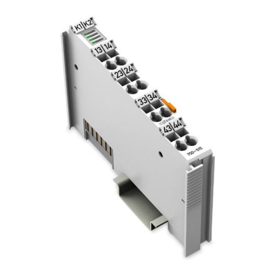
Pos : 18.4 /Serie 750 (WAGO-I/O-SYST EM)/Ger ätebesc hrei bung/Ansic ht/Digitalausgangs klemmen/Ansic ht 750- 0515 @ 24\mod_1448444555795_21.doc x @ 196229 @ @ 1 Figure 1: View Pos : 18.5 /Serie 750 (WAGO-I/O-SYST EM)/Ger ätebesc hrei bung/Ansic ht/Ansic ht C ageCl amp® _Legende mit LEDs _ohne Leis tungs kontakte @ 16\mod_1371816091053_21.doc x @ 124052 @ @ 1 Table 3: Legend for Figure “View”... -
Page 16: Connectors
Figure 2: Data Contacts Pos : 18.9.2 /Serie 750 (WAGO-I/O-SYST EM)/Wichtige Erläuterungen/Sic herheits- und sonstige Hinweis e/Achtung/Achtung: Bus kl emmen nic ht auf Gol dfeder kontakte leg en! @ 7\mod_1266318463636_21.doc x @ 50695 @ @ 1 Do not place the I/O modules on the gold spring contacts! -
Page 17: Cage Clamp ® Connectors
Device Description 750-515 4DO 250V AC 2.0A/ Relais 4NO/ Potential Free Pos : 18.13 /Serie 750 ( WAGO-I/O-SYST EM)/Gerätebeschr eibung/Ansc hlüss e/C AGE C LAMP-Ansc hlüsse - Ü bersc hrift 3 @ 6\mod_1256296337770_21.doc x @ 43674 @ 3 @ 1 ®... -
Page 18: Display Elements
Pos : 18.16 /Alle Serien (Allgemeine M odul e)/Übersc hriften/Neue Ü bersc hriften/Ebene 2Anz eigeelemente - Übersc hrift 2 @ 4\mod_1240984390875_21.doc x @ 31964 @ 2 @ 1 Display Elements Pos : 18.17 /Serie 750 ( WAGO-I/O-SYST EM)/Gerätebeschr eibung/Anzeig eel emente/Digitalausgangs klemmen/Anz eigeel emente 750- 0515 4DO ( Agn, Bgn, Cgn, Dgn) @ 24\mod_1448444785751_21.doc x @ 196235 @ @ 1 Figure 4: Display Elements Table 5: Legend for Figure “Display Elements“... -
Page 19: Schematic Diagram
Pos : 18.19 /Alle Serien (Allgemeine M odul e)/Übersc hriften/Neue Ü bersc hriften/Ebene 2Schematisc hes Sc haltbild - Ü berschrift 2 @ 4\mod_1240984441312_21.doc x @ 31967 @ 2 @ 1 Schematic Diagram Pos : 18.20 /Serie 750 ( WAGO-I/O-SYST EM)/Gerätebeschr eibung/Sc hematis che Sc haltbilder/Digital ausgangskl emmen/Sc hematis ches Sc haltbild 750-0515 @ 24\mod_1448444900788_21.doc x @ 196238 @ @ 1 Figure 5: Schematic Diagram Pos : 18.21 /D okumentati on allgemei n/Gli ederungsel emente/---Seitenwec hs el--- @ 3\mod_1221108045078_0.doc x @ 21810 @ @ 1... -
Page 20: Technical Data
Pos : 18.22 /Alle Serien (Allgemeine M odul e)/Übersc hriften/Neue Ü bersc hriften/Ebene 2T echnisc he Daten - Ü berschrift 2 @ 3\mod_1232967587687_21.doc x @ 26924 @ 2 @ 1 Technical Data Pos : 18.23 /Serie 750 ( WAGO-I/O-SYST EM)/Gerätebeschr eibung/Tec hnische D aten/Digital ausgangs kl emmen/T ec hnische D aten 750-0515 @ 24\mod_1448444984858_21.doc x @ 196241 @ 3333 @ 1 3.5.1 Device Table 6: Technical Data –... -
Page 21: Outputs
Pos : 18.25 /Serie 750 ( WAGO-I/O-SYST EM)/Gerätebeschr eibung/Tec hnische D aten/Klimatisc he U mgebungsbeding ungen/T ec hnische D aten Kli mat. U mgebungsbed. ohne erw. T emp. 0...55°C/- 25...+ 85°C @ 5\mod_1247657968368_21.doc x @ 37603 @ 3 @ 1... -
Page 22: Load Limiting Curve
750-515 4DO 250V AC 2.0A/ Relais 4NO/ Potential Free Pos : 18.27 /Serie 750 ( WAGO-I/O-SYST EM)/Gerätebeschr eibung/Tec hnische D aten/Digital ausgangs kl emmen/T ec hnische D aten 750-0515_Lastgr enz- und Lebens dauerkur ve @ 24\mod_1448445064889_21.doc x @ 196244 @ 33 @ 1 3.5.7... -
Page 23: Life Cycle Curve
WAGO-I/O-SYSTEM 750 Device Description 750-515 4DO 250V AC 2.0A/ Relais 4NO/ Potential Free 3.5.8 Life Cycle Curve Figure 7: Life Cycle Curve of the Relay Pos : 18.28 /D okumentati on allgemei n/Gli ederungsel emente/---Seitenwec hs el--- @ 3\mod_1221108045078_0.doc x @ 21810 @ @ 1 Manual Version 1.0.1... -
Page 24: Approvals
Pos : 18.41 /D okumentati on allgemei n/Gli ederungsel emente/------Leerz eile------ @ 3\mod_1224662755687_0.doc x @ 24460 @ @ 1 Pos : 18.42 /Serie 750 ( WAGO-I/O-SYST EM)/Gerätebeschr eibung/Zul ass ung en/Sc hiff/Ei nleitungssätze/Zul . in Vorberei tung Bus kl emme 750- xxxx Sc hiff, ohne Variantenangabe - Ei nleitung @ 7\mod_1274259318897_21.doc x @ 56614 @ @ 1 The following ship approvals are pending for 750-515 I/O modules: Pos : 18.43 /Alle Serien (Allgemeine M odul e)/Z ulass ungen/Schiffsz ulas sungen/ABS (American Bur eau of Shippi ng) @ 3\mod_1224055151062_0.doc x @ 24023 @ @ 1... - Page 25 WAGO-I/O-SYSTEM 750 Device Description 750-515 4DO 250V AC 2.0A/ Relais 4NO/ Potential Free LR (Lloyd’s Register) Env. 1, 2, 3, 4 Pos : 18.48 /D okumentati on allgemei n/Gli ederungsel emente/---Seitenwec hs el--- @ 3\mod_1221108045078_0.doc x @ 21810 @ @ 1 Manual Version 1.0.1...
-
Page 26: Standards And Guidelines
Standards and Guidelines Pos : 18.50 /Serie 750 ( WAGO-I/O-SYST EM)/Gerätebeschr eibung/Nor men und Richtlinien/EMV-N or men Bus klemme 750- xxxx, ohne Variantenangabe - Ei nleitung @ 4\mod_1242803944015_21.doc x @ 33642 @ @ 1 750-515 I/O modules meet the following requirements on emission and immunity of interference: Pos : 18.51 /Alle Serien (Allgemeine M odul e)/Nor men und Ric htlini en/EM V-Nor men - Standard/EM V C E-Störfestig keit EN 61000-6- 2 @ 4\mod_1242797655625_21.doc x @ 33591 @ @ 1... -
Page 27: Process Image
Process Image Pos : 21 /Serie 750 ( WAGO-I/O-SYST EM)/Proz ess abbild Kl emmenbus /Hinweis: Prozes sabbildmapping abhängig von FBK/PFC, ohne Status-/C ontr olbyte @ 6\mod_1256126797251_21.doc x @ 43340 @ @ 1 Mapping of process data in the process image of fieldbus systems The representation of the process data of some I/O modules or their variants in the process image depends on the fieldbus coupler/controller used. -
Page 28: Mounting
I/O modules with fewer power contacts. Pos : 25.2 /Serie 750 (WAGO-I/O-SYST EM)/Wic htige Erläuterungen/Sicherheits- und sonstig e Hinweis e/Vorsic ht/Vorsicht: Verl etz ungsgefahr durc h s charfkantige M ess er kontakte! @ 6\mod_1256193279401_21.doc x @ 43414 @ @ 1 Risk of injury due to sharp-edged blade contacts! The blade contacts are sharp-edged. -
Page 29: Inserting And Removing Devices
750-515 4DO 250V AC 2.0A/ Relais 4NO/ Potential Free Pos : 25.6 /Serie 750 (WAGO-I/O-SYST EM)/M ontieren/D emontieren/Geräte einfüg en und entfer nen - Ü berschrift 2 @ 3\mod_1231768483250_21.doc x @ 25950 @ 2 @ 1 Inserting and Removing Devices Pos : 25.7 /All e Seri en ( Allgemei ne Module)/Sicherheits- und s ons tige Hi nweis e/Ac htung/Achtung: Arbeiten an Ger äten nur s pannungsfr ei durc hführ en! @ 6\mod_1256193963573_21.doc x @ 43426 @ @ 1... -
Page 30: Removing The I/O Module
WAGO-I/O-SYSTEM 750 750-515 4DO 250V AC 2.0A/ Relais 4NO/ Potential Free Pos : 25.10 /Serie 750 ( WAGO-I/O-SYST EM)/Monti eren/D emonti eren/Bus kl emme entfer nen @ 4\mod_1239169375203_21.doc x @ 30334 @ 3 @ 1 5.2.2 Removing the I/O Module Remove the I/O module from the assembly by pulling the release tab. -
Page 31: Connect Devices
Check if the voltage is positively isolated. Pos : 29 /Serie 750 ( WAGO-I/O-SYST EM)/Ans chli eßen/Leiter an C AGE C LAM P ans chli eßen ( allgemei n) - Übersc hrift 2 und Text @ 3\mod_1225448660171_21.doc x @ 24928 @ 2 @ 1 ®... -
Page 32: Figure 11: Connecting A Conductor To A Cage Clamp
Connect Devices WAGO-I/O-SYSTEM 750 750-515 4DO 250V AC 2.0A/ Relais 4NO/ Potential Free ® Figure 11: Connecting a Conductor to a CAGE CLAMP Pos : 30 /D okumentation allgemei n/Glieder ungs elemente/---Seitenwechs el--- @ 3\mod_1221108045078_0.doc x @ 21810 @ @ 1 Manual Version 1.0.1... -
Page 33: Connection Examples
Pos : 31 /All e Seri en (Allgemei ne Module)/Ü berschriften/N eue Ü berschriften/Ebene 2Anschl uss beispi ele - Übersc hrift 2 @ 4\mod_1240996036328_21.doc x @ 32010 @ 2 @ 1 Connection Examples Pos : 32 /Serie 750 ( WAGO-I/O-SYST EM)/Ans chli eßen/Anschl uss beispi ele/Digitalausgangs klemmen/Ansc hl ussbeis piel e 750-0515_4DO @ 24\mod_1448444332530_21.doc x @ 196223 @ 22 @ 1 Protection Class II and III Actuators... -
Page 34: 750-515 4Do 250V Ac 2.0A/ Relais 4No/ Potential Free
750-515 4DO 250V AC 2.0A/ Relais 4NO/ Potential Free Pos : 34 /Serie 750 ( WAGO-I/O-SYST EM)/Ans chli eßen/Anschl uss beispi ele/Digitalausgangs klemmen/Kontaktsc hutz beschaltung für Rel ais klemmen @ 12\mod_1339677705690_21.doc x @ 97510 @ 2 @ 1 Protective Circuits for Contacts of Relay Modules Switching off inductive loads such as contactors and solenoid valves can generate transients with voltage peaks of up to several thousand volts. -
Page 35: Figure 18: R/C Combination
WAGO-I/O-SYSTEM 750 Connect Devices 750-515 4DO 250V AC 2.0A/ Relais 4NO/ Potential Free Table 14: Protective Circuits for Contacts of Relay Modules Protective Circuits Additional Defined Bipolar Advantages and Off-Delay Induction Effective Disadvantages Voltage Attenuation Limitation Advantages: • HF attenuation via power storage •... -
Page 36: Use In Hazardous Environments
Use in Hazardous Environments Pos : 36.2 /Serie 750 (WAGO-I/O-SYST EM)/Eins atz in Ex- Ber eichen/Ei ns atz ber eich Serie 750 @ 3\mod_1234272230203_21.doc x @ 27500 @ @ 1 The WAGO-I/O-SYSTEM 750 (electrical equipment) is designed for use in Zone 2 hazardous areas. -
Page 37: Marking Configuration Examples
Marking for Europe According to ATEX and IEC-Ex Pos : 36.6 /Serie 750 (WAGO-I/O-SYST EM)/Eins atz in Ex- Ber eichen/Beis piel bedruc kung der ATEX- und IEC- Ex-zug elass enen Bus klemmen gemäß C ENELEC und IEC_2013 @ 14\mod_1360569228625_21.doc x @ 111294 @ @ 1 Figure 19: Side Marking Example for Approved I/O Modules According to ATEX and IECEx Figure 20: Text Detail –... -
Page 38: Table 15: Description Of Marking Example For Approved I/O Modules According To Atex And Iecex
Use in Hazardous Environments WAGO-I/O-SYSTEM 750 750-515 4DO 250V AC 2.0A/ Relais 4NO/ Potential Free Table 15: Description of Marking Example for Approved I/O Modules According to ATEX and IECEx Marking Description TÜV 07 ATEX 554086 X Approving authority and certificate numbers IECEx TUN 09.0001 X... -
Page 39: Figure 21: Side Marking Example For Approved Ex I I/O Modules According To Atex And Iecex
750-515 4DO 250V AC 2.0A/ Relais 4NO/ Potential Free Pos : 36.8 /Serie 750 (WAGO-I/O-SYST EM)/Eins atz in Ex- Ber eichen/Beis piel bedruc kung der Ex-i- und IEC-Ex-i-zug elas senen Bus klemmen gemäß C ENELEC und IEC _2013 @ 14\mod_1360569320118_21.doc x @ 111298 @ @ 1 Figure 21: Side Marking Example for Approved Ex i I/O Modules According to ATEX and IECEx. - Page 40 Use in Hazardous Environments WAGO-I/O-SYSTEM 750 750-515 4DO 250V AC 2.0A/ Relais 4NO/ Potential Free Table 16: Description of Marking Example for Approved Ex i I/O Modules According to ATEX and IECEx Marking Description TÜV 07 ATEX 554086 X Approving authority and certificate numbers IECEx TUN 09.0001X...
-
Page 41: Table 16: Description Of Marking Example For Approved Ex I I/O Modules According To Atex And Iecex
WAGO-I/O-SYSTEM 750 Use in Hazardous Environments 750-515 4DO 250V AC 2.0A/ Relais 4NO/ Potential Free Table 16: Description of Marking Example for Approved Ex i I/O Modules According to ATEX and IECEx Gases Equipment group: All except mining 3(1)G Category 3 (Zone 2) equipment containing a safety... -
Page 42: Marking For America According To Nec 500
750-515 4DO 250V AC 2.0A/ Relais 4NO/ Potential Free Pos : 36.10 /Serie 750 ( WAGO-I/O-SYST EM)/Ei ns atz i n Ex-Bereic hen/Kennz eichnung für Ameri ka gemäß N EC 500 - Übersc hrift 3 @ 3\mod_1224158423187_21.doc x @ 24188 @ 3 @ 1 7.1.2... -
Page 43: Installation Regulations
Use in Hazardous Environments 750-515 4DO 250V AC 2.0A/ Relais 4NO/ Potential Free Pos : 36.13 /Alle Serien (Allgemeine M odul e)/Übersc hriften/Ebene 2Erric htungs bes timmungen - Ü bersc hrift 2 @ 3\mod_1232453624234_21.doc x @ 26370 @ 2 @ 1 Installation Regulations Pos : 36.14 /Alle Serien (Allgemeine M odul e)/Ei ns atz i n Ex-Bereic hen/Errichtungsbes timmungen Ei nleitung_2013 @ 14\mod_1360582328318_21.doc x @ 111371 @ @ 1... -
Page 44: Special Conditions For Safe Use (Tüv 14 Atex 148929 X)
Pos : 36.16 /Serie 750 ( WAGO-I/O-SYST EM)/Ei ns atz i n Ex-Bereic hen/Besonder e Beding ung en für den sic her en Ex- Betrieb gem. AT EX-Z ertifi kat TÜV 14 ATEX 148929_X @ 21\mod_1416995371807_21.doc... -
Page 45: Special Conditions For Safe Use (Atex Certificate Tüv 12 Atex 106032 X)
Pos : 36.18 /Serie 750 ( WAGO-I/O-SYST EM)/Ei ns atz i n Ex-Bereic hen/Besonder e Beding ung en für den sic her en Ex- Betrieb gem. AT EX-Z ertifi kat TÜV 12 ATEX 106032x_2013_2 @ 15\mod_1368620479454_21.doc... -
Page 46: Special Conditions For Safe Use (Iec-Ex Certificate Tun 14.0035X)
Pos : 36.20 /Serie 750 ( WAGO-I/O-SYST EM)/Ei ns atz i n Ex-Bereic hen/Besonder e Beding ung en für den sic her en Ex- Betrieb gem. IEC-Ex-Z ertifi kat TUN 14.0035 X_2014 @ 21\mod_1416995779884_21.doc... -
Page 47: Special Conditions For Safe Use (Iec-Ex Certificate Iecex Tun 12.0039 X)
Pos : 36.22 /Serie 750 ( WAGO-I/O-SYST EM)/Ei ns atz i n Ex-Bereic hen/Besonder e Beding ung en für den sic her en Ex- Betrieb gem. IEC-Ex-Z ertifi kat TUN 12.0039 X_2013_2 @ 15\mod_1368620821493_21.doc... -
Page 48: Special Conditions For Safe Use According To Ansi/Isa 12.12.01
750-515 4DO 250V AC 2.0A/ Relais 4NO/ Potential Free Pos : 36.24 /Serie 750 ( WAGO-I/O-SYST EM)/Ei ns atz i n Ex-Bereic hen/Errichtungsbesti mmung en AN SI ISA 12.12.01_2013_2_für 750-439, -633, - 663/000-003 @ 21\mod_1417518338537_21.doc x @ 169812 @ 3 @ 1 7.2.5... -
Page 49: List Of Figures
List of Figures 750-515 4DO 250V AC 2.0A/ Relais 4NO/ Potential Free Pos : 38 /D okumentation allgemei n/Verz eic hniss e/Abbil dungs verz eic hnis - Übersc hrift oG und Verz eichnis @ 3\mod_1219222916765_21.doc x @ 21080 @ @ 1 List of Figures Figure 1: View ....................... -
Page 50: List Of Tables
List of Tables WAGO-I/O-SYSTEM 750 750-515 4DO 250V AC 2.0A/ Relais 4NO/ Potential Free Pos : 40 /D okumentation allgemei n/Verz eic hniss e/Tabell enverz eichnis - Übersc hrift oG und Verz eichnis @ 3\mod_1219222958703_21.doc x @ 21084 @ @ 1 List of Tables Table 1: Number Notation .................. - Page 51 WAGO-I/O-SYSTEM 750 750-515 4DO 250V AC 2.0A/ Relais 4NO/ Potential Free Pos : 42 /D okumentation allgemei n/Einband/Einband H andbuc h - Leers eite für durc h 2 teilbar e Seitenzahl (Standar ddr uc k) @ 3\mod_1219230851078_0.doc x @ 21123 @ @ 1 Manual Version 1.0.1...
- Page 52 Pos : 43 /D okumentation allgemei n/Einband/Einband H andbuc h - R üc kseite 2015 @ 9\mod_1285229376516_21.doc x @ 64944 @ @ 1 WAGO Kontakttechnik GmbH & Co. KG Postfach 2880 • D-32385 Minden Hansastraße 27 • D-32423 Minden Phone: 05 71/8 87 –...
Need help?
Do you have a question about the 750-515 and is the answer not in the manual?
Questions and answers