
Related Manuals for WAGO 750-535


Summary of Contents for WAGO 750-535
- Page 1 Manual WAGO-I/O-SYSTEM 750 750-535 2DO 24V DC Ex i 2-Channel Digital Output Module 24 V DC, Ex i Version 1.2.0, gültig ab HW-Version 06...
- Page 2 We wish to point out that the software and hardware terms as well as the trademarks of companies used and/or mentioned in the present manual are generally protected by trademark or patent. WAGO is a registered trademark of WAGO Verwaltungsgesellschaft mbH. Manual Version 1.2.0, gültig ab HW-Version 06...
-
Page 3: Table Of Contents
Legal Bases .................... 9 2.1.1 Subject to Changes ................9 2.1.2 Personnel Qualifications ..............9 2.1.3 Use of the WAGO-I/O-SYSTEM 750 in Compliance with Underlying Provisions ................ 9 2.1.4 Technical Condition of Specified Devices......... 10 2.1.4.1 Disposal ..................10 Safety Advice (Precautions) ..............11 Device Description .................. - Page 4 Table of Contents WAGO-I/O-SYSTEM 750 750-535 2DO 24V DC Ex i Connection Example ................37 Use in Hazardous Environments ............38 Marking Configuration Examples ............39 7.1.1 Marking for Europe According to ATEX and IECEx ......39 7.1.2 Marking for America (NEC) and Canada (CEC) ....... 43 Installation Regulations.................
-
Page 5: Notes About This Documentation
This documentation is only applicable to the I/O module 750-535 (2DO 24V DC Ex i). The I/O module 750-535 shall only be installed and operated according to the instructions in this manual and in the manual for the used fieldbus coupler/controller. -
Page 6: Symbols
Notes about this Documentation WAGO-I/O-SYSTEM 750 750-535 2DO 24V DC Ex i Symbols Personal Injury! Indicates a high-risk, imminently hazardous situation which, if not avoided, will result in death or serious injury. Personal Injury Caused by Electric Current! Indicates a high-risk, imminently hazardous situation which, if not avoided, will result in death or serious injury. - Page 7 WAGO-I/O-SYSTEM 750 Notes about this Documentation 750-535 2DO 24V DC Ex i Additional Information: Refers to additional information which is not an integral part of this documentation (e.g., the Internet). Manual Version 1.2.0, gültig ab HW-Version 06...
-
Page 8: Number Notation
Notes about this Documentation WAGO-I/O-SYSTEM 750 750-535 2DO 24V DC Ex i Number Notation Table 1: Number Notation Number Code Example Note Decimal Normal notation Hexadecimal 0x64 C notation Binary '100' In quotation marks, nibble separated '0110.0100' with dots (.) -
Page 9: Important Notes
2.1.1 Subject to Changes WAGO Kontakttechnik GmbH & Co. KG reserves the right to provide for any alterations or modifications. WAGO Kontakttechnik GmbH & Co. KG owns all rights arising from the granting of patents or from the legal protection of utility patents. -
Page 10: Technical Condition Of Specified Devices
These modules contain no parts that can be serviced or repaired by the user. The following actions will result in the exclusion of liability on the part of WAGO Kontakttechnik GmbH & Co. KG: •... -
Page 11: Safety Advice (Precautions)
Install the device only in appropriate housings, cabinets or in electrical operation rooms! The WAGO-I/O-SYSTEM 750 and its components are an open system. As such, install the system and its components exclusively in appropriate housings, cabinets or in electrical operation rooms. Allow access to such equipment and fixtures to authorized, qualified staff only by means of specific keys or tools. - Page 12 Important Notes WAGO-I/O-SYSTEM 750 750-535 2DO 24V DC Ex i Do not use any contact spray! Do not use any contact spray. The spray may impair contact area functionality in connection with contamination. Do not reverse the polarity of connection lines! Avoid reverse polarity of data and power supply lines, as this may damage the devices involved.
-
Page 13: Device Description
An arrangement in groups within the group of potentials is not necessary. The I/O module 750-535 can be used with all fieldbus couplers/controllers of the WAGO-I/O-SYSTEM 750. The meaning of the LEDs is described in the “Display Elements” section. -
Page 14: View
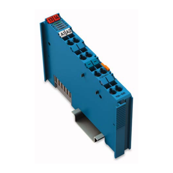
Device Description WAGO-I/O-SYSTEM 750 750-535 2DO 24V DC Ex i View Figure 1: View Table 3: Legend for Figure “View” Pos. Description Details See Section Marking possibility with Mini- Status LEDs “Device Description” > “Display Elements” Data contacts “Device Description” > “Connectors”... -
Page 15: Connectors
WAGO-I/O-SYSTEM 750 Device Description 750-535 2DO 24V DC Ex i Connectors 3.2.1 Data Contacts/Local Bus Communication between the fieldbus coupler/controller and the I/O modules as well as the system supply of the I/O modules is carried out via the local bus. It is comprised of 6 data contacts, which are available as self-cleaning gold spring contacts. -
Page 16: Power Jumper Contacts/Field Supply
The blade contacts are sharp-edged. Handle the I/O module carefully to prevent injury. The I/O module 750-535 has 2 self-cleaning power jumper contacts that supply and transmit power for the field side. The contacts on the left side of the I/O module are designed as blade contacts and those on the right side as spring contacts. -
Page 17: Cage Clamp
WAGO-I/O-SYSTEM 750 Device Description 750-535 2DO 24V DC Ex i ® 3.2.3 CAGE CLAMP Connectors ® Figure 4: CAGE CLAMP Connectors ® Table 5: Legend for Figure “CAGE CLAMP Connectors“ Channel Designation Connector Function DO 1 Output DO 1: Signal voltage... -
Page 18: Display Elements
Green Output DO 1: Signal voltage (1) Output DO 2: Signal voltage (0) State DO 1 Green Output DO 2: Signal voltage (1) Operating Elements The I/O module 750-535 has no operating elements. Manual Version 1.2.0, gültig ab HW-Version 06... -
Page 19: Schematic Diagram
WAGO-I/O-SYSTEM 750 Device Description 750-535 2DO 24V DC Ex i Schematic Diagram Figure 6: Schematic Diagram Manual Version 1.2.0, gültig ab HW-Version 06... -
Page 20: Technical Data
Device Description WAGO-I/O-SYSTEM 750 750-535 2DO 24V DC Ex i Technical Data 3.6.1 Device Data Table 7: Technical Data ‒ Device Width 12 mm Height (from upper edge of 35 DIN rail) 64 mm Depth 100 mm Weight Approx. 49.5 g 3.6.2... -
Page 21: Figure 7: Output Characteristic, Resistive Load
WAGO-I/O-SYSTEM 750 Device Description 750-535 2DO 24V DC Ex i Figure 7: Output Characteristic, Resistive Load With a load resistor of 200 Ω or more, the output characteristic is primarily determined by the I/O module's internal resistance. With a lower load resistor, the I/O module limits the output current. -
Page 22: Explosion Protection
Device Description WAGO-I/O-SYSTEM 750 750-535 2DO 24V DC Ex i 3.6.5 Explosion Protection Table 11: Technical Data ‒ Explosion protection Voltage supply via power jumper = 27.3 V contacts ( LK1, LK2) = 2.1 W Interface circuit (local bus) = 5 V... -
Page 23: Climatic Environmental Conditions
WAGO-I/O-SYSTEM 750 Device Description 750-535 2DO 24V DC Ex i Table 13: Technical Data – Power Jumper Contacts Power jumper contacts Blade/spring contact, self-cleaning Table 14: Technical Data – Data Contacts Data contacts Slide contact, hard gold plated, self- cleaning 3.6.7... -
Page 24: Approvals
UL E175199 for use in Ordinary Location The following Ex approvals have been granted to 750-535 I/O modules: TÜV 12 ATEX 106032 X I M2 (M1) Ex d [ia Ma] I Mb II 3 (1) G Ex ec [ia Ga] IIC T4 Gc II 3 (1) D Ex tc [ia Da] IIIC T135°C Dc... - Page 25 WAGO-I/O-SYSTEM 750 Device Description 750-535 2DO 24V DC Ex i The following ship approvals have been granted to 750-535 I/O modules: ABS (American Bureau of Shipping) Federal Maritime and Hydrographic Agency BV (Bureau Veritas) DNV (Det Norske Veritas) Class B GL (Germanischer Lloyd) Cat.
-
Page 26: Standards And Guidelines
Device Description WAGO-I/O-SYSTEM 750 750-535 2DO 24V DC Ex i Standards and Guidelines 750-535 I/O modules meet the following standards and guidelines: EU Directive 2014/34/EU Explosive atmosphere EN 60079-0 Devices – General requirements Explosive atmosphere IEC 60079-7 Equipment protection by increased safety "e"... - Page 27 WAGO-I/O-SYSTEM 750 Device Description 750-535 2DO 24V DC Ex i Explosive atmospheres CAN/CSA-C22.2 No. 60079-15 Equipment Protection by Intrinsic Safety "n" UL Standard for Safety – UL 508 for Industrial Control Equipment American National Standard – ANSI/ISA 12.12.01 for Nonincendive Electrical Equipment for Use in Class I and II, Division 2 and Class III.
-
Page 28: Process Image
Process Image WAGO-I/O-SYSTEM 750 750-535 2DO 24V DC Ex i Process Image Mapping of process data in the process image of fieldbus systems The representation of the process data of some I/O modules or their variants in the process image depends on the fieldbus coupler/controller used. Please take this information from the section “I/O Modules”... -
Page 29: Mounting
Don't forget the bus end module! Always plug a bus end module (750-600) onto the end of the fieldbus node! You must always use a bus end module at all fieldbus nodes with WAGO-I/O- SYSTEM 750 fieldbus couplers/controllers to guarantee proper data transfer. -
Page 30: Inserting And Removing Devices
Mounting WAGO-I/O-SYSTEM 750 750-535 2DO 24V DC Ex i Inserting and Removing Devices Perform work on devices only if they are de-energized! Working on energized devices can damage them. Therefore, turn off the power supply before working on the devices. -
Page 31: Removing The I/O Module
WAGO-I/O-SYSTEM 750 Mounting 750-535 2DO 24V DC Ex i 5.2.2 Removing the I/O Module Remove the I/O module from the assembly by pulling the release tab. Figure 10: Removing the I/O Module (Example) Electrical connections for data or power jumper contacts are disconnected when removing the I/O module. -
Page 32: Connect Devices
Only one conductor may be connected to each CAGE CLAMP Do not connect more than one conductor at one single connection! If more than one conductor must be routed to one connection, these must be connected in an up-circuit wiring assembly, for example using WAGO feed- through terminals. ®... -
Page 33: Power Supply Concept
WAGO-I/O-SYSTEM 750 Connect Devices 750-535 2DO 24V DC Ex i Power Supply Concept Ex i I/O modules shall only be supplied via Ex i 24 VDC power supply module! Ex i I/O modules shall only be operated with an Ex i 24 VDC power supply module. -
Page 34: Figure 12: Supply Principle Ex I
Connect Devices WAGO-I/O-SYSTEM 750 750-535 2DO 24V DC Ex i Figure 12: Supply Principle Ex i Figure 13: Overvoltage Categories Table 17: Legend for Figure “Overvoltage Categories” Explanation Fieldbus coupler/controller Filter module (if required) Ex i supply module Ex i I/O modules End module Both overvoltage categories and rated surge voltage acc. -
Page 35: Power Supply Concept In Marine Applications
WAGO-I/O-SYSTEM 750 Connect Devices 750-535 2DO 24V DC Ex i 6.2.1 Power Supply Concept in Marine Applications The appropriate filter module is required when using Ex i I/O modules in marine applications! Power supply to the Ex i supply module shall be provided via the appropriate filter module when using Ex i I/O modules in marine applications! Modules approved to category EMC1 (marine applications): 750-626 or 750-626/020-000. -
Page 36: Figure 15: Power Supply Concept, Category Emc2 (Marine Applications)
Connect Devices WAGO-I/O-SYSTEM 750 750-535 2DO 24V DC Ex i Figure 15: Power Supply Concept, Category EMC2 (Marine Applications) Table 19: Legend for Figure “Power Supply Concept, Category EMC2 (Marine Applications)” Explanation Fieldbus coupler/controller Filter module (750-626, 750-626/020-000, 750-624, 750-624/020-000) -
Page 37: Connection Example
WAGO-I/O-SYSTEM 750 Connect Devices 750-535 2DO 24V DC Ex i Connection Example Figure 16: Connecting Diagram Manual Version 1.2.0, gültig ab HW-Version 06... -
Page 38: Use In Hazardous Environments
WAGO-I/O-SYSTEM 750 750-535 2DO 24V DC Ex i Use in Hazardous Environments The WAGO-I/O-SYSTEM 750 (electrical equipment) is designed for use in Zone 2 hazardous areas. The following sections include both the general identification of components (devices) and the installation regulations to be observed. The individual subsections of the “Installation Regulations”... -
Page 39: Marking Configuration Examples
WAGO-I/O-SYSTEM 750 Use in Hazardous Environments 750-535 2DO 24V DC Ex i Marking Configuration Examples 7.1.1 Marking for Europe According to ATEX and IECEx Figure 17: Marking Example According to ATEX and IECEx Figure 18: Text Detail – Marking Example According to ATEX and IECEx Manual Version 1.2.0, gültig ab HW-Version 06... -
Page 40: Table 20: Description Of Marking Example According To Atex And Iecex
Use in Hazardous Environments WAGO-I/O-SYSTEM 750 750-535 2DO 24V DC Ex i Table 20: Description of Marking Example According to ATEX and IECEx Marking Description TUEV 07 ATEX 554086 X Approving authority resp. certificate numbers IECEx TUN 09.0001 X Dust... -
Page 41: Figure 19: Marking Example For Approved Ex I I/O Module According To Atex And Iecex
WAGO-I/O-SYSTEM 750 Use in Hazardous Environments 750-535 2DO 24V DC Ex i Figure 19: Marking Example for Approved Ex i I/O Module According to ATEX and IECEx Figure 20: Text Detail – Marking Example for Approved Ex i I/O Module According to ATEX and... -
Page 42: Table 21: Description Of Marking Example For Approved Ex I I/O Module According To Atex And Iecex
Use in Hazardous Environments WAGO-I/O-SYSTEM 750 750-535 2DO 24V DC Ex i Table 21: Description of Marking Example for Approved Ex i I/O Module According to ATEX and IECEx Marking Description TUEV 12 ATEX 106032 X Approving authority resp. certificate numbers... -
Page 43: Marking For America (Nec) And Canada (Cec)
WAGO-I/O-SYSTEM 750 Use in Hazardous Environments 750-535 2DO 24V DC Ex i 7.1.2 Marking for America (NEC) and Canada (CEC) Figure 21: Marking Example According to NEC Figure 22: Text Detail – Marking Example According to NEC 500 Table 22: Description of Marking Example According to NEC 500... -
Page 44: Figure 23: Text Detail - Marking Example For Approved Ex I I/O Module
Use in Hazardous Environments WAGO-I/O-SYSTEM 750 750-535 2DO 24V DC Ex i Figure 23: Text Detail – Marking Example for Approved Ex i I/O Module According to NEC 505 Table 23: Description of Marking Example for Approved Ex i I/O Module According to NEC 505... -
Page 45: Figure 25: Text Detail - Marking Example For Approved Ex I I/O Modules
WAGO-I/O-SYSTEM 750 Use in Hazardous Environments 750-535 2DO 24V DC Ex i Figure 25: Text Detail – Marking Example for Approved Ex i I/O Modules According to CEC 18 attachment J Table 25: Description of Marking Example for Approved Ex i I/O Modules According to CEC 18... -
Page 46: Installation Regulations
Use in Hazardous Environments WAGO-I/O-SYSTEM 750 750-535 2DO 24V DC Ex i Installation Regulations For the installation and operation of electrical equipment in hazardous areas, the valid national and international rules and regulations which are applicable at the installation location must be carefully followed. - Page 47 WAGO-I/O-SYSTEM 750 Use in Hazardous Environments 750-535 2DO 24V DC Ex i Explosive atmosphere occurring simultaneously with assembly, installation or repair work must be ruled out. Among other things, these include the following activities • Insertion and removal of components •...
-
Page 48: Special Notes Regarding Ansi/Isa Ex
Use in Hazardous Environments WAGO-I/O-SYSTEM 750 750-535 2DO 24V DC Ex i 7.2.2 Special Notes Regarding ANSI/ISA Ex For ANSI/ISA Ex acc. to UL File E198726, the following additional requirements apply: • Use in Class I, Division 2, Group A, B, C, D or non-hazardous areas only •... -
Page 49: Appendix
WAGO-I/O-SYSTEM 750 Appendix 750-535 2DO 24V DC Ex i Appendix Rated Surge Voltage Table 26: Rated Surge Voltage Nominal voltage of Line-to-neutral voltage, Rated surge voltage the power supply system derived from the nominal (mains) acc. to IEC 60038 3... -
Page 50: List Of Figures
List of Figures WAGO-I/O-SYSTEM 750 750-535 2DO 24V DC Ex i List of Figures Figure 1: View ....................14 Figure 2: Data Contacts ..................15 Figure 3: Power Jumper Contacts ..............16 ® Figure 4: CAGE CLAMP Connectors ..............17 Figure 5: Display Elements.................18 Figure 6: Schematic Diagram ................19... -
Page 51: List Of Tables
WAGO-I/O-SYSTEM 750 List of Tables 750-535 2DO 24V DC Ex i List of Tables Table 1: Number Notation ................... 8 Table 2: Font Conventions .................. 8 Table 3: Legend for Figure “View” ..............14 Table 4: Legend for Figure “Power Jumper Contacts” ........16 ®... - Page 52 WAGO Kontakttechnik GmbH & Co. KG Postfach 2880 • 32385 Minden Hansastraße 27 • 32423 Minden Phone: 0571/887 – 0 Fax: 0571/887 – 169 E-Mail: info@wago.com Internet: http://www.wago.com...
Need help?
Do you have a question about the 750-535 and is the answer not in the manual?
Questions and answers