
Subscribe to Our Youtube Channel
Related Manuals for WAGO 750-538


Summary of Contents for WAGO 750-538
- Page 1 Manual WAGO-I/O-SYSTEM 750 750-538 2DO RELAY Ex i 2-Channel Relay Output Module, 100 VAC, 30 VDC, Ex i, isolated outputs, 2 changeover contacts Version 1.4.1...
- Page 2 We wish to point out that the software and hardware terms as well as the trademarks of companies used and/or mentioned in the present manual are generally protected by trademark or patent. WAGO is a registered trademark of WAGO Verwaltungsgesellschaft mbH. Manual Version 1.4.1...
-
Page 3: Table Of Contents
WAGO-I/O-SYSTEM 750 Table of Contents 750-538 2DO RELAY Ex i Table of Contents Notes about this Documentation ............. 5 Validity of this Documentation..............5 Copyright ....................5 Symbols ....................6 Number Notation ..................8 Font Conventions ................... 8 Important Notes ..................9 Legal Bases .................... - Page 4 Table of Contents WAGO-I/O-SYSTEM 750 750-538 2DO RELAY Ex i Power Supply Concept ................. 37 6.2.1 Power Supply Concept for Marine Applications in Ex i ..... 39 Connection Example ................42 Protective Circuits for Contacts of Relay Modules ........ 43 Use in Hazardous Environments ............
-
Page 5: Notes About This Documentation
This documentation is only applicable to the I/O module 750-538 (2DO RELAY Ex i). The I/O module 750-538 shall only be installed and operated according to the instructions in this manual and in the manual for the used fieldbus coupler or controller. -
Page 6: Symbols
Notes about this Documentation WAGO-I/O-SYSTEM 750 750-538 2DO RELAY Ex i Symbols Personal Injury! Indicates a high-risk, imminently hazardous situation which, if not avoided, will result in death or serious injury. Personal Injury Caused by Electric Current! Indicates a high-risk, imminently hazardous situation which, if not avoided, will result in death or serious injury. - Page 7 WAGO-I/O-SYSTEM 750 Notes about this Documentation 750-538 2DO RELAY Ex i Additional Information: Refers to additional information which is not an integral part of this documentation (e.g., the Internet). Manual Version 1.4.1...
-
Page 8: Number Notation
Notes about this Documentation WAGO-I/O-SYSTEM 750 750-538 2DO RELAY Ex i Number Notation Table 1: Number Notation Number Code Example Note Decimal Normal notation Hexadecimal 0x64 C notation Binary '100' In quotation marks, nibble separated '0110.0100' with dots (.) Font Conventions... -
Page 9: Important Notes
2.1.1 Subject to Changes WAGO Kontakttechnik GmbH & Co. KG reserves the right to provide for any alterations or modifications. WAGO Kontakttechnik GmbH & Co. KG owns all rights arising from the granting of patents or from the legal protection of utility patents. -
Page 10: Technical Condition Of Specified Devices
These modules contain no parts that can be serviced or repaired by the user. The following actions will result in the exclusion of liability on the part of WAGO Kontakttechnik GmbH & Co. KG: •... -
Page 11: 2.1.4.1.2 Packaging
WAGO-I/O-SYSTEM 750 Important Notes 750-538 2DO RELAY Ex i Environmentally friendly disposal benefits health and protects the environment from harmful substances in electrical and electronic equipment. • Observe national and local regulations for the disposal of electrical and electronic equipment. -
Page 12: Safety Advice (Precautions)
Important Notes WAGO-I/O-SYSTEM 750 750-538 2DO RELAY Ex i Safety Advice (Precautions) For installing and operating purposes of the relevant device to your system the following safety precautions shall be observed: Do not work on devices while energized! All power sources to the device shall be switched off prior to performing any installation, repair or maintenance work. - Page 13 WAGO-I/O-SYSTEM 750 Important Notes 750-538 2DO RELAY Ex i Ensure proper contact with the DIN-rail! Proper electrical contact between the DIN-rail and device is necessary to maintain the EMC characteristics and function of the device. Replace defective or damaged devices! Replace defective or damaged device/module (e.g., in the event of deformed...
- Page 14 Important Notes WAGO-I/O-SYSTEM 750 750-538 2DO RELAY Ex i Avoid electrostatic discharge! The devices are equipped with electronic components that may be destroyed by electrostatic discharge when touched. Please observe the safety precautions against electrostatic discharge per DIN EN 61340-5-1/-3. When handling the devices, please ensure that environmental factors (personnel, work space and packaging) are properly grounded.
-
Page 15: Device Description
Device Description 750-538 2DO RELAY Ex i Device Description The digital output module 750-538 (2DO RELAY Ex i) controls intrinsically safe actuators operating in hazardous environments of zone 0 and 1, e. g. magnetic valves, contactors, optical or acoustic actuators. - Page 16 Any configuration of the I/O module is possible within an intrinsically safe segment when configuring the fieldbus node. An arrangement in groups within the group of potentials is not necessary. The I/O module 750-538 can be used with all fieldbus couplers/controllers of the WAGO-I/O-SYSTEM 750. Manual...
-
Page 17: View
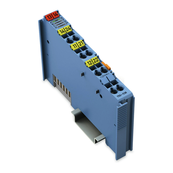
WAGO-I/O-SYSTEM 750 Device Description 750-538 2DO RELAY Ex i View Figure 1: View Table 3: Legend for Figure “View” Pos. Description Details See Section Marking possibility with Mini- Status LEDs “Device Description” > “Display Elements” Data contacts “Device Description” > “Connectors”... -
Page 18: Connectors
Device Description WAGO-I/O-SYSTEM 750 750-538 2DO RELAY Ex i Connectors 3.2.1 Data Contacts/Local Bus Communication between the fieldbus coupler/controller and the I/O modules as well as the system supply of the I/O modules is carried out via the local bus. The contacting for the local bus consists of 6 data contacts, which are available as self-cleaning gold spring contacts. -
Page 19: Power Jumper Contacts/Field Supply
The blade contacts are sharp-edged. Handle the I/O module carefully to prevent injury. Do not touch the blade contacts. The I/O module 750-538 has 2 self-cleaning power jumper contacts that supply and transmit power for the field side. The contacts on the left side of the I/O module are designed as blade contacts and those on the right side as spring contacts. -
Page 20: Cage Clamp
Device Description WAGO-I/O-SYSTEM 750 750-538 2DO RELAY Ex i 3.2.3 CAGE CLAMP ® Connectors Figure 4: CAGE CLAMP ® Connectors Table 5: Legend for Figure “CAGE CLAMP ® Connectors” Channel Designation Connector Function DO 1 Output DO 1: CO (NO) 14... -
Page 21: Display Elements
WAGO-I/O-SYSTEM 750 Device Description 750-538 2DO RELAY Ex i Display Elements Figure 5: Display Elements Table 6: Legend for Figure “Display Elements” Chann Designation LED State Function NO-contact DO 1 open, Status of NC-contact /DO 1 closed relay 1 gree... -
Page 22: Operating Elements
Device Description WAGO-I/O-SYSTEM 750 750-538 2DO RELAY Ex i Operating Elements The I/O module 750-538 has no operating elements. Schematic Diagram (only one channel shown) Figure 6: Schematic Diagram Manual Version 1.4.1... -
Page 23: Technical Data
WAGO-I/O-SYSTEM 750 Device Description 750-538 2DO RELAY Ex i Technical Data 3.6.1 Device Data Table 7: Technical Data ‒ Device Width 12 mm Height (from upper edge of 35 DIN rail) 64 mm Depth 100 mm Weight Approx. 48.5 g 3.6.2... -
Page 24: Outputs
Device Description WAGO-I/O-SYSTEM 750 750-538 2DO RELAY Ex i 3.6.4 Outputs Table 10: Technical Data ‒ Outputs Number of outputs 2 change-over relays Load Resistive, inductive or lamp load Switching voltage 100 VAC / 30 VDC max. Switching current 0.5 AAC / 1 ADC max. -
Page 25: Climatic Environmental Conditions
WAGO-I/O-SYSTEM 750 Device Description 750-538 2DO RELAY Ex i Table 14: Technical Data – Data Contacts Data contacts Slide contact, hard gold plated, self- cleaning 3.6.7 Climatic Environmental Conditions Table 15: Technical Data – Climatic Environmental Conditions Surrounding air temperature, operation 0 °C … 55 °C Surrounding air temperature, storage −25 °C …... -
Page 26: Table 1: Electrical Safety
Device Description WAGO-I/O-SYSTEM 750 750-538 2DO RELAY Ex i Table 16: Electrical Safety Safe Separation (Reinforced Insulation) per EN 61010-2-201 “System/Field”, “System/Output” and “between outputs” Secondary working voltage 100 VAC Overvoltage category II Pollution degree 2 “Field/Output” Secondary working voltage 34 VAC... -
Page 27: Approvals
Location Korea Certification MSIP-REM-W43-DOM750 The following Ex approvals have been granted to 750-538 I/O modules: TÜV 12 ATEX 106032 X I M2 (M1) Ex d [ia Ma] I Mb II 3 (1) G Ex ec [ia Ga] IIC T4 Gc II 3 (1) D Ex tc [ia Da] IIIC T135°C Dc... - Page 28 Cat. A, B, C, D (EMC 1) More information about approvals. Detailed references to the approvals are listed in the document “Overview Approvals WAGO I/O SYSTEM 750”, which you can find via the internet under: www.wago.com DOWNLOADS Documentation System Description.
-
Page 29: Standards And Guidelines
WAGO-I/O-SYSTEM 750 Device Description 750-538 2DO RELAY Ex i Standards and Guidelines 750-538 I/O modules meet the following standards and guidelines: ATEX Directive 2014/34/EU Explosive atmosphere EN 60079-0 Devices – General requirements Explosive atmosphere IEC 60079-7 Equipment protection by increased safety "e"... - Page 30 Device Description WAGO-I/O-SYSTEM 750 750-538 2DO RELAY Ex i Explosive atmospheres CAN/CSA-C22.2 No. 60079-15 Equipment Protection by Intrinsic Safety "n" UL Standard for Safety – UL 508 for Industrial Control Equipment Safety requirements for electrical IEC 61010-2-201 equipment for measurement,...
-
Page 31: Process Image
WAGO-I/O-SYSTEM 750 Process Image 750-538 2DO RELAY Ex i Process Image Table 17: Output Bits Bit 1 Bit 0 DO 2 DO 1 DO 1 Signal state DO 1 – digital output channel 1 DO 2 Signal state DO 2 – digital output channel 2 Manual Version 1.4.1... -
Page 32: Mounting
Mounting WAGO-I/O-SYSTEM 750 750-538 2DO RELAY Ex i Mounting Do not work when devices are energized! High voltage can cause electric shock or burns. Switch off all power to the device prior to performing any installation, repair or maintenance work. -
Page 33: Mounting Sequence
Always plug a bus end module (750-600) onto the end of the fieldbus node! You must always use a bus end module at all fieldbus nodes with WAGO I/O SYSTEM 750 fieldbus couplers or controllers to guarantee proper data transfer. -
Page 34: Inserting And Removing Devices
Mounting WAGO-I/O-SYSTEM 750 750-538 2DO RELAY Ex i Inserting and Removing Devices 5.2.1 Inserting the I/O Module Position the I/O module in such a way that the groove and spring are connected to the preceding and following components. Figure 7: Inserting I/O Module (Example) Press the I/O module into the assembly until the I/O module snaps into the carrier rail. -
Page 35: Removing The I/O Module
WAGO-I/O-SYSTEM 750 Mounting 750-538 2DO RELAY Ex i Once the I/O module has snapped into place, the electrical connections for the data contacts and power contacts (if any) to the head station or to the preceding and, if applicable, following I/O module are established. -
Page 36: Connect Devices
Do not connect more than one conductor at one single connection! If more than one conductor must be routed to one connection, these must be connected in an up-circuit wiring assembly, for example using WAGO feed- through terminals. For opening the CAGE CLAMP ®... -
Page 37: Power Supply Concept
Further information about explosion prevention can be found in section “Use in Hazardous Environments”! The Ex i I/O module (750-538) receives the 24 V voltage supply potential and the 0V potential for the field level from an upstream Ex i I/O module or from an Ex i Manual Version 1.4.1... -
Page 38: Figure 11: Supply Principle Ex I
750-538 2DO RELAY Ex i power supply module via the power contacts designed as blade contacts. The Ex i I/O module (750-538) provides these potentials to subsequent I/O modules via the power contacts designed as spring contacts. Figure 11: Supply Principle Ex i Table 18: Legend for Figure “Ex i Power Supply Concept”... -
Page 39: Power Supply Concept For Marine Applications In Ex I
WAGO-I/O-SYSTEM 750 Connect Devices 750-538 2DO RELAY Ex i Figure 12: Overvoltage Categories Table 19: Legend for Figure “Overvoltage Categories” Pos. Explanation Fieldbus coupler/controller Filter module (if required) Ex i supply module Ex i I/O modules End module Overvoltage categories and rated surge voltage see EN 61010-2-201. -
Page 40: Figure 13: Power Supply Concept For Marine Applications In Ex I - Class A
Connect Devices WAGO-I/O-SYSTEM 750 750-538 2DO RELAY Ex i Power Supply Concept for Marine Applications in Ex i Class A Figure 13: Power Supply Concept for Marine Applications in Ex i – Class A (shown with 750- 624/xxx-xxx for Field 2) Table 20: Legend for figure “Power Supply Concept for Marine Applications in Ex i –... -
Page 41: Figure 14: Power Supply Concept For Marine Applications In Ex I - Class B
WAGO-I/O-SYSTEM 750 Connect Devices 750-538 2DO RELAY Ex i Power Supply Concept for Marine Applications in Ex i Class B Figure 14: Power Supply Concept for Marine Applications in Ex i – Class B (shown with 750- 626/xxx-xxx for Field 2) Table 22: Legend for figure “Power Supply Concept for Marine Applications in Ex i –... -
Page 42: Connection Example
Connect Devices WAGO-I/O-SYSTEM 750 750-538 2DO RELAY Ex i Connection Example The following figure shows an example with 2 intrinsically safe devices connected to the channels 1 and 2. Figure 15: Connection Example With 2 Intrinsically Safe Devices Manual Version 1.4.1... -
Page 43: Protective Circuits For Contacts Of Relay Modules
WAGO-I/O-SYSTEM 750 Connect Devices 750-538 2DO RELAY Ex i Protective Circuits for Contacts of Relay Modules Switching off inductive loads such as contactors and solenoid valves can generate transients with voltage peaks of up to several thousand volts. Very often, these transients exceed the permissible limits specified in the EMC standards. -
Page 44: Figure 20: R/C Combination
Connect Devices WAGO-I/O-SYSTEM 750 750-538 2DO RELAY Ex i Table 24: Protective Circuits for Contacts of Relay Modules Protective Circuits Additional Defined Bipolar Advantages and Off-Delay Induction Effective Disadvantages Voltage Attenuation Limitation Advantages: • HF attenuation via power storage •... -
Page 45: Use In Hazardous Environments
Use in Hazardous Environments 750-538 2DO RELAY Ex i Use in Hazardous Environments The WAGO I/O SYSTEM 750 (electrical equipment) is designed for use in Zone 2 hazardous areas and shall be used in accordance with the marking and installation regulations. -
Page 46: Marking Configuration Examples
Use in Hazardous Environments WAGO-I/O-SYSTEM 750 750-538 2DO RELAY Ex i Marking Configuration Examples 7.1.1 Marking for Europe According to ATEX and IECEx Figure 21: Marking Example According to ATEX and IECEx Figure 22: Text Detail – Marking Example According to ATEX and IECEx Manual Version 1.4.1... -
Page 47: Table 1: Description Of Marking Example According To Atex And Iecex
WAGO-I/O-SYSTEM 750 Use in Hazardous Environments 750-538 2DO RELAY Ex i Table 25: Description of Marking Example According to ATEX and IECEx Marking Description TUEV 07 ATEX 554086 X Approving authority resp. certificate numbers IECEx TUN 09.0001 X Dust Equipment group: All except mining... -
Page 48: Figure 23: Marking Example For Approved Ex I I/O Module According To
Use in Hazardous Environments WAGO-I/O-SYSTEM 750 750-538 2DO RELAY Ex i Figure 23: Marking Example for Approved Ex i I/O Module According to ATEX and IECEx Figure 24: Text Detail – Marking Example for Approved Ex i I/O Module According to ATEX and... -
Page 49: Table 1: Description Of Marking Example For Approved Ex I I/O Module According To Atex And Iecex
WAGO-I/O-SYSTEM 750 Use in Hazardous Environments 750-538 2DO RELAY Ex i Table 26: Description of Marking Example for Approved Ex i I/O Module According to ATEX and IECEx Marking Description TUEV 12 ATEX 106032 X Approving authority resp. certificate numbers... -
Page 50: Marking For The United States Of America (Nec) And Canada (Cec)
Use in Hazardous Environments WAGO-I/O-SYSTEM 750 750-538 2DO RELAY Ex i 7.1.2 Marking for the United States of America (NEC) and Canada (CEC) Figure 25: Marking Example According to NEC Figure 26: Text Detail – Marking Example According to NEC 500... -
Page 51: Figure 27: Text Detail - Marking Example For Approved Ex I I/O Module
WAGO-I/O-SYSTEM 750 Use in Hazardous Environments 750-538 2DO RELAY Ex i Figure 27: Text Detail – Marking Example for Approved Ex i I/O Module According to NEC 505 Table 28: Description of Marking Example for Approved Ex i I/O Module According to NEC 505... -
Page 52: Figure 29: Text Detail - Marking Example For Approved Ex I I/O Modules
Use in Hazardous Environments WAGO-I/O-SYSTEM 750 750-538 2DO RELAY Ex i Figure 29: Text Detail – Marking Example for Approved Ex i I/O Modules According to CEC 18 attachment J Table 30: Description of Marking Example for Approved Ex i I/O Modules According to CEC 18... -
Page 53: Installation Regulations
WAGO-I/O-SYSTEM 750 Use in Hazardous Environments 750-538 2DO RELAY Ex i Installation Regulations For the installation and operation of electrical equipment in hazardous areas, the valid national and international rules and regulations which are applicable at the installation location must be carefully followed. - Page 54 Use in Hazardous Environments WAGO-I/O-SYSTEM 750 750-538 2DO RELAY Ex i Explosive atmosphere occurring simultaneously with assembly, installation or repair work must be ruled out. Among other things, these include the following activities • Insertion and removal of components •...
-
Page 55: Special Notes Regarding Ansi/Isa Ex
• subject to overloads! These include, e.g., motor circuits. • WARNING – When installing I/O module 750-538, “Control Drawing No. 750538” in the manual must be strictly observed! Additional Information Proof of certification is available on request. Also take note of the information given on the operating and assembly instructions. -
Page 56: Control Drawing
Use in Hazardous Environments WAGO-I/O-SYSTEM 750 750-538 2DO RELAY Ex i 7.2.3 Control Drawing Figure 30: Control Drawing No: 750538 Manual Version 1.4.1... -
Page 57: List Of Figures
WAGO-I/O-SYSTEM 750 List of Figures 750-538 2DO RELAY Ex i List of Figures Figure 1: View ....................17 Figure 2: Data Contacts ..................18 Figure 3: Power Jumper Contacts ..............19 Figure 4: CAGE CLAMP ® Connectors ..............20 Figure 5: Display Elements.................21 Figure 6: Schematic Diagram ................22 Figure 7: Inserting I/O Module (Example) ............34... -
Page 58: List Of Tables
List of Tables WAGO-I/O-SYSTEM 750 750-538 2DO RELAY Ex i List of Tables Table 1: Number Notation ................... 8 Table 1: Font Conventions .................. 8 Table 1: Legend for Figure “View” ..............17 Table 1: Legend for Figure “Power Jumper Contacts” ........19 Table 1: Legend for Figure “CAGE CLAMP... - Page 59 WAGO-I/O-SYSTEM 750 750-538 2DO RELAY Ex i Manual Version 1.4.1...
- Page 60 WAGO Kontakttechnik GmbH & Co. KG Postfach 2880 • D - 32385 Minden Hansastraße 27 • D - 32423 Minden Phone: +49 571 887 – 0 Fax: +49 571 887 – 844169 E-Mail: info@wago.com Internet: www.wago.com...
Need help?
Do you have a question about the 750-538 and is the answer not in the manual?
Questions and answers