
Subscribe to Our Youtube Channel
Related Manuals for WAGO 750-536


Summary of Contents for WAGO 750-536
- Page 1 Fieldbus Independent I/O Modules 8 DO DC 24 V 0.5 A, negative Switching 750-536 Manual Version 1.0.2...
- Page 2 • General Copyright © 2006 by WAGO Kontakttechnik GmbH & Co. KG All rights reserved. WAGO Kontakttechnik GmbH & Co. KG Hansastraße 27 D-32423 Minden Phone: +49 (0) 571/8 87 – 0 Fax: +49 (0) 571/8 87 – 1 69 E-Mail: info@wago.com...
-
Page 3: Table Of Contents
Number Notation..................5 Safety Notes ..................... 6 Scope ......................6 2 I/O Modules ....................7 Digital Output Modules................7 2.1.1 750-536 [8 DO DC 24 V 0.5 A, Low-Side Switching] ....... 7 2.1.1.1 View....................7 2.1.1.2 Description..................8 2.1.1.3 Display Elements ................9 2.1.1.4... -
Page 4: Important Comments
WAGO Kontakttechnik GmbH & Co. KG declines all liability resulting from improper action and damage to WAGO products and third party products due to non-observance of the information contained in this manual. -
Page 5: Symbols
More information References on additional literature, manuals, data sheets and internet pages. 1.3 Number Notation Number Code Example Note Decimal normal notation Hexadecimal 0x64 C notation Binary '100' within inverted commas, '0110.0100' nibble separated with dots WAGO-I/O-SYSTEM 750 I/O Modules... -
Page 6: Safety Notes
1.5 Scope This manual describes the Digital Output Module 750-536 8 DO DC 24 V 0.5 A, of the modular WAGO-I/O-SYSTEM 750. Handling, assembly and start-up are described in the manual of the Fieldbus Coupler. Therefore this documentation is valid only in the connection with the appropriate manual. -
Page 7: O Modules
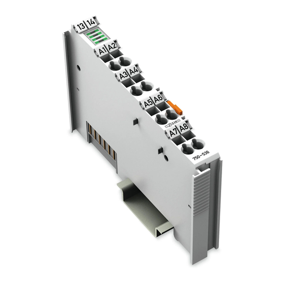
750-536 [8 DO DC 24 V 0.5 A, Low-Side Switching] • 7 View 2 I/O Modules 2.1 Digital Output Modules 2.1.1 750-536 [8 DO DC 24 V 0.5 A, Low-Side Switching] 8 Channel Digital Output Module DC 24 V 0.5 A, short-circuit-protected, low-side switching 2.1.1.1 View 13 14 Status DO 1 …... -
Page 8: Description
8 • 750-536 [8 DO DC 24 V 0.5 A, Low-Side Switching] Description 2.1.1.2 Description The connected load is switched via the digital output from the control system. The module has eight output channels and enables the direct wiring of eight actuators to the connections DO 1 to DO 8. -
Page 9: Display Elements
750-536 [8 DO DC 24 V 0.5 A, Low-Side Switching] • 9 Display Elements 2.1.1.3 Display Elements Chan Designatio Status Function Status Output DO 1: not active green DO 1 Output DO 1: active Status Output DO 2: not active... -
Page 10: Technical Data
10 • 750-536 [8 DO DC 24 V 0.5 A, Low-Side Switching] Technical Data 2.1.1.5 Technical Data Module Specific Data Number of outputs Current consumption (internal) 25 mA max. Voltage via power jumper contacts DC 24 V (-25 % ... +30 %) -
Page 11: Process Image
750-536 [8 DO DC 24 V 0.5 A, Low-Side Switching] • 11 Process Image More Information Detailed references to the approvals are listed in the document "Overview Approvals WAGO-I/O-SYSTEM 750", which you can find on the CD ROM ELECTRONICC Tools and Docs (Item-No.: 0888-0412) or in the internet under: www.wago.com... - Page 12 WAGO Kontakttechnik GmbH & Co. KG Postfach 2880 • D-32385 Minden Hansastraße 27 • D-32423 Minden Phone: 05 71/8 87 – 0 Fax: 05 71/8 87 – 1 69 E-Mail: info@wago.com Internet: http://www.wago.com...
Need help?
Do you have a question about the 750-536 and is the answer not in the manual?
Questions and answers