Sign In
Upload
Manuals
Brands
WAGO Manuals
Control Unit
4AO U/I
WAGO 4AO U/I Manuals
Manuals and User Guides for WAGO 4AO U/I. We have
1
WAGO 4AO U/I manual available for free PDF download: Manual
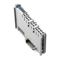
WAGO 4AO U/I Manual (102 pages)
4AO U/I 4-Channel Analog Output Module; Voltage/Current For WAGO-I/O-SYSTEM 750
Brand:
WAGO
| Category:
Control Unit
| Size: 4.8 MB
Table of Contents
Table of Contents
3
1 Notes about this Documentation
5
Validity of this Documentation
5
Copyright
5
Symbols
6
Number Notation
8
Font Conventions
8
Table 1: Number Notation
8
Table 2: Font Conventions
8
2 Important Notes
9
Legal Bases
9
Subject to Changes
9
Personnel Qualifications
9
Use of the 750 Series in Compliance with Underlying Provisions
9
Technical Condition of Specified Devices
10
Disposal
10
Electrical and Electronic Equipment
10
Packaging
11
Safety Advice (Precautions)
12
3 Device Description
15
Table 3: Compatibility List 750-564
16
Table 24: ±5 V
16
Table 29: ±10 V
17
View
18
Figure 1: View
18
Table 4: Legend for Figure "View
18
Connectors
19
Data Contacts/Local Bus
19
Figure 2: Data Contacts
19
Power Jumper Contacts/Field Supply
20
Figure 3: Power Jumper Contacts
20
Table 5: Legend for Figure "Power Jumper Contacts
20
Push-In CAGE CLAMP ® Connectors
21
Figure 4: Push-In CAGE CLAMP ® Connectors
21
Table 6: Legend for Figure "Push-In CAGE CLAMP ® Connectors
21
Display Elements
22
Figure 5: Display Elements
22
Table 7: Legend for Figure "Display Elements
22
Schematic Diagram
23
Figure 6: Schematic Diagram
23
Technical Data
24
Device
24
Power Supply
24
Communication
24
Table 8: Technical Data - Device
24
Table 9: Technical Data - Power Supply
24
Table 10: Technical Data - Communication
24
Outputs
25
Table 11: Technical Data - Outputs
25
Climatic Environmental Conditions
26
Table 12: Max. Error/Temperature Drift by Output Range
26
Table 13: Technical Data - Field Wiring
26
Table 14: Technical Data - Climatic Environmental Conditions
26
Approvals
27
Standards and Guidelines
28
4 Process Image
29
Overview
29
Table 15: Process Image ("Standard") - 750-564 I/O Module
30
Table 16: Process Image ("Advanced") - 750-564 I/O Module
30
Control and Status Bytes
31
Table 17: Control Byte CH1_C0
31
Table 18: Status Byte CH1_S0
32
Prozess Data
33
Overview of Signal Types
33
Table 19: Overview of Signal Types
33
Prozess Value (Voltage)
34
Table 20: 0-5 V (16-Bit Resolution)
34
Table 21: 0-5 V (15-Bit Resolution)
34
Table 22: 1-5 V (16-Bit Resolution)
34
Table 23: 1-5 V (15-Bit Resolution)
34
Table 25: 0-10 V (16-Bit Resolution)
35
Table 26: 0-10 V (15-Bit Resolution)
35
Table 27: 2-10 V (16-Bit Resolution)
36
Table 28: 2-10 V (15-Bit Resolution)
36
Table 30: 0-12 V (16-Bit Resolution)
37
Table 31: 0-12 V (15-Bit Resolution)
38
Process Values (Current)
39
Table 33: 0-10 Ma (16-Bit Resolution)
39
Table 34: 0-10 Ma (15-Bit Resolution)
39
Table 35: 2-10 Ma (16-Bit Resolution)
39
Table 36: 2-10 Ma (15-Bit Resolution)
40
Table 37: ±10 Ma
40
Table 38: 0-20 Ma (16-Bit Resolution)
41
Table 39: 0-20 Ma (15-Bit Resolution)
42
Table 40: 4-20 Ma (16-Bit Resolution)
42
Table 41: 4-20 Ma (15-Bit Resolution)
43
Table 42: ±20 Ma
44
Table 43: 0-22 Ma (16-Bit Resolution)
45
Table 44: 0-22 Ma (15-Bit Resolution)
46
Table 45: ±20 Ma
47
Table 46: 0-12 Ma (16-Bit Resolution)
48
Table 47: 0-12 Ma (15-Bit Resolution)
48
Table 48: ±12 Ma
49
5 Mounting
50
Mounting Sequence
51
Inserting and Removing Devices
52
Inserting the I/O Module
52
Figure 7: Inserting I/O Module (Example)
52
Figure 8: Snap the I/O Module into Place (Example)
52
Removing the I/O Module
53
Figure 9: Removing the I/O Module (Example)
53
6 Connect Devices
54
Connecting a Conductor to the Push-In CAGE CLAMP
54
Figure 10: Connecting a Conductor to a Push-In CAGE CLAMP
55
Connection Examples
56
Figure 11: Connection Example - 2-Conductor Connection Current/Voltage
56
Figure 12: Connection Example - 4-Conductor Connection with Sense Lines
57
7 Commissioning
58
Table 49: Settings Using Tools
58
Configuration and Parameterization with WAGO-I/O-CHECK
59
Control Mode
60
Figure 13: WAGO-I/O-CHECK User Interface (Example)
60
Figure 14: Selecting I/O Module
60
Figure 15: "Control Mode" Menu Item
61
Figure 16: "Process Data" Menu Item
61
Figure 17: Setting Process Output Data
61
Parameterization Dialog
62
Figure 18: I/O Module Parameterization Dialog
62
Title Bar
63
Information Bar
63
Buttons
63
Table 50: Buttons
63
Menu
64
Settings Via the Menu
64
Common
64
Figure 19: "Common" Menu Item
64
Table 51: "Common" Menu Item
65
Channel Settings
66
Figure 20: Menu Items "Channel 1
66
Figure 21: Marking Modified Parameters
67
Table 52: Menu Items "Channel 1
67
Scaling
69
Figure 22: "Scaling" Menu Item
70
Calibration
71
Table 53: "Scaling" Menu Item for each Channel
71
Figure 23: "Calibration" Menu Item
72
Configuration and Parameterization with E!Cockpit
73
Table 54: "Calibration" Menu Item for each Channel
73
Configuration and Parameterization Via GSD File
74
Table 55: PROFIBUS DP Configuration
74
Figure 24: Example "Device-Specific Parameters" Dialog with PROFIBUS DP
75
Table 56: Configuration of 750-375(/025-000) and 750-377(/025-000)
75
Figure 25: Example "General Module/Channel Parameters" Dialog with
76
Figure 26: Example "Specific Module/Channel Parameters" Dialog with
76
Figure 27: Example of Optional "Profienergy Parameters" Dialog with
77
Table 57: Device-Specific Parameters and Specific Module/Channel
77
Table 58: General Module/Channel Parameters
78
Table 59: General Module/Channel Parameters
78
Table 60: Specific Module/Channel Parameters - PROFINET IO Couplers
78
Table 61: Profienergy Parameters
79
8 Scaling Measured Values
80
Table 62: Variable Legend - Scaling Process Values
80
9 Calibrating Measured Values
81
Example of Determining Gain and Offset
81
Table 63: Variable Legend - Calibrating Measured Values
81
10 Diagnostics
83
Error States and Possible Causes
83
Diagnostics Via Display Elements
83
Table 64: Error States in Current Output Mode
83
Table 65: Error States in Voltage Output Mode
83
Table 66: Signal Evaluation for each Channel - Status LED
83
Table 67: Signal Evaluation for each Channel - Error LED
84
11 Use in Hazardous Environments
85
Marking Configuration Examples
86
Marking for Europe According to ATEX and Iecex
86
Figure 28: Marking Example Per ATEX and Iecex
86
Figure 29: Text Detail - Marking Example Per ATEX and Iecex
86
Table 68: Description of the Marking Example Per ATEX and Iecex
87
Figure 30: Marking Example of an Approved I/O Module Ex I Per ATEX and
88
Figure 31: Text Detail - Marking Example of an Approved I/O Module Ex I Per
88
Table 69: Description of the Marking Example of an Approved I/O Module Ex I Per ATEX and Iecex
89
Marking for the United States of America (NEC) and Canada (CEC)
90
Figure 32: Marking Example According to NEC
90
Figure 33: Text Detail - Marking Example According to NEC 500
90
Table 70: Description of Marking Example According to NEC 500
90
Figure 34: Text Detail - Marking Example for Approved Ex I I/O Module
91
Figure 35: Text Detail - Marking Example for Approved Ex I I/O Module
91
Table 71: Description of Marking Example for Approved Ex I I/O Module
91
Table 72: Description of Marking Example for Approved Ex I I/O Modules
91
Figure 36: Text Detail - Marking Example for Approved Ex I I/O Modules
92
Table 73: Description of Marking Example for Approved Ex I I/O Modules
92
Installation Regulations
93
Special Notes Including Explosion Protection
93
Table 32: ±12 V
93
Special Notes Regarding UL Hazardous Location
95
12 Service
96
Firmware Update/Downgrade
96
Recalibration
97
WAGO UII (Unique Item Identifier)
98
List of Figures
99
List of Tables
100
Advertisement
Advertisement
Related Products
WAGO 4AO 4-20mA
WAGO 4055143907804
WAGO 4055144057171
WAGO 4055143415040
WAGO 4055143908016
WAGO 4PS
WAGO 4PU
WAGO 1AI DMS
WAGO 2 AI 4-20 mA S.E.
WAGO 2789-9023
WAGO Categories
I/O Systems
Control Unit
Power Supply
Switch
Controller
More WAGO Manuals
Login
Sign In
OR
Sign in with Facebook
Sign in with Google
Upload manual
Upload from disk
Upload from URL