
Related Manuals for WAGO 750-509


Summary of Contents for WAGO 750-509
- Page 1 Manual WAGO-I/O-SYSTEM 750 2DO 230V AC 0.3A/SSR 750-509 2-Channel Digital Output Module 230 VAC/DC, with Solid State Relay 0.3 A Version 1.1.0...
- Page 2 WAGO-I/O-SYSTEM 750 750-509 2DO 230V AC 0.3A/SSR © 2015 by WAGO Kontakttechnik GmbH & Co. KG All rights reserved. WAGO Kontakttechnik GmbH & Co. KG Hansastraße 27 D-32423 Minden Phone: +49 (0) 571/8 87 – 0 Fax: +49 (0) 571/8 87 – 1 69 E-Mail: info@wago.com...
-
Page 3: Table Of Contents
2.1.1 Subject to Changes ................9 2.1.2 Personnel Qualifications ............... 9 2.1.3 Use of the WAGO-I/O-SYSTEM 750 in Compliance with Underlying Provisions ................9 2.1.4 Technical Condition of Specified Devices ......... 10 Safety Advice (Precautions) ..............11 Device Description ..................13 View ...................... - Page 4 Table of Contents WAGO-I/O-SYSTEM 750 750-509 2DO 230V AC 0.3A/SSR Protective Circuits for Contacts of Relay Modules ......... 33 Use in Hazardous Environments .............. 35 Marking Configuration Examples ............36 7.1.1 Marking for Europe According to ATEX and IEC-Ex ...... 36 7.1.2...
-
Page 5: Notes About This Documentation
This documentation is only applicable to the I/O module 750-509 (2DO 230V AC 0.3A/SSR). The I/O module 750-509 shall only be installed and operated according to the instructions in this manual and in the manual for the used fieldbus coupler/controller. -
Page 6: Symbols
Notes about this Documentation WAGO-I/O-SYSTEM 750 750-509 2DO 230V AC 0.3A/SSR Symbols Personal Injury! Indicates a high-risk, imminently hazardous situation which, if not avoided, will result in death or serious injury. Personal Injury Caused by Electric Current! Indicates a high-risk, imminently hazardous situation which, if not avoided, will result in death or serious injury. - Page 7 WAGO-I/O-SYSTEM 750 Notes about this Documentation 750-509 2DO 230V AC 0.3A/SSR Additional Information: Refers to additional information which is not an integral part of this documentation (e.g., the Internet). Manual Version 1.1.0...
-
Page 8: Number Notation
Notes about this Documentation WAGO-I/O-SYSTEM 750 750-509 2DO 230V AC 0.3A/SSR Number Notation Table 1: Number Notation Number Code Example Note Decimal Normal notation Hexadecimal 0x64 C notation Binary '100' In quotation marks, nibble separated with '0110.0100' dots (.) Font Conventions... -
Page 9: Important Notes
2.1.1 Subject to Changes WAGO Kontakttechnik GmbH & Co. KG reserves the right to provide for any alterations or modifications that serve to increase the efficiency of technical progress. WAGO Kontakttechnik GmbH & Co. KG owns all rights arising from the granting of patents or from the legal protection of utility patents. -
Page 10: Technical Condition Of Specified Devices
WAGO-I/O-SYSTEM 750 750-509 2DO 230V AC 0.3A/SSR Appropriate housing (per 94/9/EG) is required when operating the WAGO-I/O- SYSTEM 750 in hazardous environments. Please note that a prototype test certificate must be obtained that confirms the correct installation of the system in a housing or switch cabinet. -
Page 11: Safety Advice (Precautions)
Install the device only in appropriate housings, cabinets or in electrical operation rooms! The WAGO-I/O-SYSTEM 750 and its components are an open system. As such, install the system and its components exclusively in appropriate housings, cabinets or in electrical operation rooms. Allow access to such equipment and fixtures to authorized, qualified staff only by means of specific keys or tools. - Page 12 Important Notes WAGO-I/O-SYSTEM 750 750-509 2DO 230V AC 0.3A/SSR Do not use any contact spray! Do not use any contact spray. The spray may impair contact area functionality in connection with contamination. Do not reverse the polarity of connection lines! Avoid reverse polarity of data and power supply lines, as this may damage the devices involved.
-
Page 13: Device Description
750-509 2DO 230V AC 0.3A/SSR Device Description The I/O module 750-509 (2DO 230V AC 0.3A/SSR) uses voltages up to 230 V AC/DC for connected actuators or universal supply voltage loads. The I/O module has 2 output channels, providing a direct connection to 2 actuators with functional ground connection. -
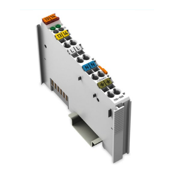
Page 14: View
Device Description WAGO-I/O-SYSTEM 750 750-509 2DO 230V AC 0.3A/SSR View Figure 1: View Table 3: Legend for Figure “View” Pos. Description Details See Section Marking possibility with Mini- Status LEDs “Device Description” > “Display Elements” Data contacts “Device Description” > “Connectors”... -
Page 15: Connectors
WAGO-I/O-SYSTEM 750 Device Description 750-509 2DO 230V AC 0.3A/SSR Connectors 3.2.1 Data Contacts/Internal Bus Communication between the fieldbus coupler/controller and the I/O modules as well as the system supply of the I/O modules is carried out via the internal bus. It is comprised of 6 data contacts, which are available as self-cleaning gold spring contacts. -
Page 16: Power Jumper Contacts/Field Supply
The blade contacts are sharp-edged. Handle the I/O module carefully to prevent injury. The I/O module 750-509 has 3 self-cleaning power jumper contacts that supply and transmit power for the field side. The contacts on the left side of the I/O module are designed as male contacts and the contacts on the right side as spring contacts. - Page 17 WAGO-I/O-SYSTEM 750 Device Description 750-509 2DO 230V AC 0.3A/SSR Do not exceed maximum current via power jumper contacts! The maximum current to flow through the power jumper contacts is 10 A. Greater currents can damage the contacts. When configuring your system, ensure that this current is not exceeded. If exceeded, insert an additional supply module.
-
Page 18: Cage Clamp
Device Description WAGO-I/O-SYSTEM 750 750-509 2DO 230V AC 0.3A/SSR ® 3.2.3 CAGE CLAMP Connectors ® Figure 4: CAGE CLAMP Connectors ® Table 5: Legend for Figure “CAGE CLAMP Connectors” Channel Designation Connector Function DO 1 Output DO 1: Signal voltage... -
Page 19: Display Elements
WAGO-I/O-SYSTEM 750 Device Description 750-509 2DO 230V AC 0.3A/SSR Display Elements Figure 5: Display Elements Table 6: Legend for Figure “Display Elements” Channel Designation State Function Output DO 1: Signal voltage “0” Status DO 1 Green Output DO 1: Signal voltage “1”... -
Page 20: Schematic Diagram
Device Description WAGO-I/O-SYSTEM 750 750-509 2DO 230V AC 0.3A/SSR Schematic Diagram Figure 6: Schematic Diagram Manual Version 1.1.0... -
Page 21: Technical Data
WAGO-I/O-SYSTEM 750 Device Description 750-509 2DO 230V AC 0.3A/SSR Technical Data 3.5.1 Device Table 7: Technical Data – Device Width 12 mm Height (from upper edge of DIN 35 rail) 64 mm Depth 100 mm Weight Approx. 55 g 3.5.2 Power Supply Table 8: Technical Data –... -
Page 22: Connection Type
Device Description WAGO-I/O-SYSTEM 750 750-509 2DO 230V AC 0.3A/SSR 3.5.5 Connection Type Table 11: Technical Data – Field Wiring ® Wire connection CAGE CLAMP Cross section 0.08 mm² … 2.5 mm², AWG 28 … 14 Stripped lengths 8 mm … 9 mm / 0.33 in Table 12: Technical Data –... -
Page 23: Approvals
Conformity Marking UL508 Korea Certification MSIP-REM-W43-DOM750 The following Ex approvals have been granted to 750-509 I/O modules: TÜV 07 ATEX 554086 X I M2 Ex d I Mb II 3 G Ex nA IIC T4 Gc II 3 D Ex tc IIIC T135°C Dc Ambient temperature range: 0 °C ≤... - Page 24 Device Description WAGO-I/O-SYSTEM 750 750-509 2DO 230V AC 0.3A/SSR The following ship approvals have been granted to 750-509 I/O modules: ABS (American Bureau of Shipping) Federal Maritime and Hydrographic Agency BV (Bureau Veritas) DNV (Det Norske Veritas) Class B GL (Germanischer Lloyd) Cat.
-
Page 25: Standards And Guidelines
WAGO-I/O-SYSTEM 750 Device Description 750-509 2DO 230V AC 0.3A/SSR Standards and Guidelines 750-509 I/O modules meet the following requirements on emission and immunity of interference: EMC CE-Emission of interference acc. to EN 61000-6-4 EMC CE-Immunity to interference acc. to EN 61000-6-2... -
Page 26: Process Image
Process Image WAGO-I/O-SYSTEM 750 750-509 2DO 230V AC 0.3A/SSR Process Image Mapping of process data in the process image of fieldbus systems The representation of the process data of some I/O modules or their variants in the process image depends on the fieldbus coupler/controller used. Please take this information from the section “Fieldbus Specific Design of the Process Data”... -
Page 27: Mounting
Don't forget the bus end module! Always plug a bus end module 750-600 onto the end of the fieldbus node! You must always use a bus end module at all fieldbus nodes with WAGO-I/O- SYSTEM 750 fieldbus couplers/controllers to guarantee proper data transfer. -
Page 28: Inserting And Removing Devices
Mounting WAGO-I/O-SYSTEM 750 750-509 2DO 230V AC 0.3A/SSR Inserting and Removing Devices Perform work on devices only if they are de-energized! Working on energized devices can damage them. Therefore, turn off the power supply before working on the devices. 5.2.1... -
Page 29: Removing The I/O Module
WAGO-I/O-SYSTEM 750 Mounting 750-509 2DO 230V AC 0.3A/SSR 5.2.2 Removing the I/O Module Remove the I/O module from the assembly by pulling the release tab. Figure 9: Removing the I/O Module (Example) Electrical connections for data or power jumper contacts are disconnected when removing the I/O module. -
Page 30: Connect Devices
Only one conductor may be connected to each CAGE CLAMP Do not connect more than one conductor at one single connection! If more than one conductor must be routed to one connection, these must be connected in an up-circuit wiring assembly, for example using WAGO feed- through terminals. Exception: If it is unavoidable to jointly connect 2 conductors, then you must use a ferrule to join the wires together. -
Page 31: Connection Examples
WAGO-I/O-SYSTEM 750 Connect Devices 750-509 2DO 230V AC 0.3A/SSR Connection Examples 6.2.1 2-Wire Connection, Protection Class I Actuators Figure 11: Connection Example, 2-Wire Connection for Protection Class I Actuators 6.2.2 2-Wire Connection, Protection Class II Actuators Figure 12: Connection Example, 2-Wire Connection for Protection Class II Actuators (Protective... -
Page 32: 3-Wire Connection, Protection Class I Actuators
Connect Devices WAGO-I/O-SYSTEM 750 750-509 2DO 230V AC 0.3A/SSR 6.2.3 3-Wire Connection, Protection Class I Actuators Figure 13: Connection Example, 3-Wire Connection for Protection Class I Actuators 6.2.4 3-Wire Connection, Protection Class II Actuators Figure 14: Connection Example, 3-Wire Connection for Protection Class II Actuators (Protective... -
Page 33: Protective Circuits For Contacts Of Relay Modules
WAGO-I/O-SYSTEM 750 Connect Devices 750-509 2DO 230V AC 0.3A/SSR Protective Circuits for Contacts of Relay Modules Switching off inductive loads such as contactors and solenoid valves can generate transients with voltage peaks of up to several thousand volts. Very often, these transients exceed the permissible limits specified in the EMC standards. -
Page 34: Figure 19: R/C Combination
Connect Devices WAGO-I/O-SYSTEM 750 750-509 2DO 230V AC 0.3A/SSR Table 16: Protective Circuits for Contacts of Relay Modules Protective Circuits Additional Defined Bipolar Advantages and Off-Delay Induction Effective Disadvantages Voltage Attenuation Limitation Advantages: • HF attenuation via power storage •... -
Page 35: Use In Hazardous Environments
Use in Hazardous Environments 750-509 2DO 230V AC 0.3A/SSR Use in Hazardous Environments The WAGO-I/O-SYSTEM 750 (electrical equipment) is designed for use in Zone 2 hazardous areas. The following sections include both the general identification of components (devices) and the installation regulations to be observed. The individual subsections of the “Installation Regulations”... -
Page 36: Marking Configuration Examples
Use in Hazardous Environments WAGO-I/O-SYSTEM 750 750-509 2DO 230V AC 0.3A/SSR Marking Configuration Examples 7.1.1 Marking for Europe According to ATEX and IEC-Ex Figure 20: Side Marking Example for Approved I/O Modules According to ATEX and IECEx Figure 21: Text Detail – Marking Example for Approved I/O Modules According to ATEX and IECEx. -
Page 37: Table 17: Description Of Marking Example For Approved I/O Modules According To Atex And Iecex
WAGO-I/O-SYSTEM 750 Use in Hazardous Environments 750-509 2DO 230V AC 0.3A/SSR Table 17: Description of Marking Example for Approved I/O Modules According to ATEX and IECEx Printing on Text Description TÜV 07 ATEX 554086 X Approving authority and certificate numbers IECEx TUN 09.0001 X... -
Page 38: Figure 22: Side Marking Example For Approved Ex I I/O Modules According To Atex And Iecex
Use in Hazardous Environments WAGO-I/O-SYSTEM 750 750-509 2DO 230V AC 0.3A/SSR Figure 22: Side Marking Example for Approved Ex i I/O Modules According to ATEX and IECEx. Figure 23: Text Detail – Marking Example for Approved Ex i I/O Modules According to ATEX and IECEx. - Page 39 WAGO-I/O-SYSTEM 750 Use in Hazardous Environments 750-509 2DO 230V AC 0.3A/SSR Table 18: Description of Marking Example for Approved Ex i I/O Modules According to ATEX and IECEx Inscription Text Description TÜV 07 ATEX 554086 X Approving authority and certificate numbers IECEx TUN 09.0001X...
-
Page 40: Table 18: Description Of Marking Example For Approved Ex I I/O Modules According To Atex And Iecex
Use in Hazardous Environments WAGO-I/O-SYSTEM 750 750-509 2DO 230V AC 0.3A/SSR Table 18: Description of Marking Example for Approved Ex i I/O Modules According to ATEX and IECEx Gases Equipment group: All except mining 3(1)G Category 3 (Zone 2) equipment containing a safety... -
Page 41: Marking For America According To Nec 500
WAGO-I/O-SYSTEM 750 Use in Hazardous Environments 750-509 2DO 230V AC 0.3A/SSR 7.1.2 Marking for America According to NEC 500 Figure 24: Side Marking Example for I/O Modules According to NEC 500 Figure 25: Text Detail – Marking Example for Approved I/O Modules According to NEC 500... -
Page 42: Installation Regulations
Use in Hazardous Environments WAGO-I/O-SYSTEM 750 750-509 2DO 230V AC 0.3A/SSR Installation Regulations For the installation and operation of electrical equipment in hazardous areas, the valid national and international rules and regulations which are applicable at the installation location must be carefully followed. -
Page 43: Special Conditions For Safe Use (Atex Certificate Tüv 07 Atex 554086 X)
ATEX 554086 X) For use as Gc- or Dc-apparatus (in zone 2 or 22) the Field bus Independent I/O Modules WAGO-I/O-SYSTEM 750-*** shall be erected in an enclosure that fulfils the requirements of the applicable standards (see the marking) EN 60079-0, EN 60079-11, EN 60079-15 and EN 60079-31. -
Page 44: Special Conditions For Safe Use (Atex Certificate Tüv 12 Atex 106032 X)
ATEX 106032 X) For use as Gc- or Dc-apparatus (in zone 2 or 22) the Field bus Independent I/O Modules WAGO-I/O-SYSTEM 750-*** Ex i shall be erected in an enclosure that fulfils the requirements of the applicable standards (see the marking) EN 60079-0, EN 60079-11, EN 60079-15 and EN 60079-31. -
Page 45: Special Conditions For Safe Use (Iec-Ex Certificate Tun 09.0001 X)
09.0001 X) For use as Gc- or Dc-apparatus (in zone 2 or 22) the Field bus Independent I/O Modules WAGO-I/O-SYSTEM 750-*** shall be erected in an enclosure that fulfils the requirements of the applicable standards (see the marking) IEC 60079-0, IEC 60079-11, IEC 60079-15 and IEC 60079-31. -
Page 46: Special Conditions For Safe Use (Iec-Ex Certificate Iecex Tun 12.0039 X)
TUN 12.0039 X) For use as Gc- or Dc-apparatus (in zone 2 or 22) the Field bus independent I/O Modules WAGO-I/O-SYSTEM 750-*** Ex i shall be erected in an enclosure that fulfils the requirements of the applicable standards (see the marking) IEC 60079-0, IEC 60079-11, IEC 60079-15, IEC 60079-31. -
Page 47: Special Conditions For Safe Use According To Ansi/Isa
WAGO-I/O-SYSTEM 750 Use in Hazardous Environments 750-509 2DO 230V AC 0.3A/SSR 7.2.5 Special Conditions for Safe Use According to ANSI/ISA 12.12.01 “This equipment is suitable for use in Class I, Division 2, Groups A, B, C, D or non-hazardous locations only.”... -
Page 48: List Of Figures
List of Figures WAGO-I/O-SYSTEM 750 750-509 2DO 230V AC 0.3A/SSR List of Figures Figure 1: View ....................... 14 Figure 2: Data Contacts ..................15 Figure 3: Power Jumper Contacts ................. 16 ® Figure 4: CAGE CLAMP Connectors..............18 Figure 5: Display Elements ................... 19 Figure 6: Schematic Diagram ................ -
Page 49: List Of Tables
WAGO-I/O-SYSTEM 750 List of Tables 750-509 2DO 230V AC 0.3A/SSR List of Tables Table 1: Number Notation ..................8 Table 2: Font Conventions ..................8 Table 3: Legend for Figure “View” ..............14 Table 4: Legend for Figure “Power Jumper Contacts” ......... 16 ®... - Page 50 WAGO Kontakttechnik GmbH & Co. KG Postfach 2880 • D-32385 Minden Hansastraße 27 • D-32423 Minden Phone: +49/5 71/8 87 – 0 Fax: +49/5 71/8 87 – 1 69 E-Mail: info@wago.com Internet: http://www.wago.com...
Need help?
Do you have a question about the 750-509 and is the answer not in the manual?
Questions and answers