
Subscribe to Our Youtube Channel
Related Manuals for WAGO 750-532


Summary of Contents for WAGO 750-532
- Page 1 Fieldbus Independent I/O Modules 4 DO DC 24 V 0,5 A, High-Side Switching, Diagnostics 750-532 Manual Version 1.0.1...
- Page 2 • General Copyright © 2006 by WAGO Kontakttechnik GmbH & Co. KG All rights reserved. WAGO Kontakttechnik GmbH & Co. KG Hansastraße 27 D-32423 Minden Phone: +49 (0) 571/8 87 – 0 Fax: +49 (0) 571/8 87 – 1 69 E-Mail: info@wago.com...
-
Page 3: Table Of Contents
Number Notation..................5 Safety Notes ..................... 6 Scope ......................6 2 I/O Modules ....................7 Digital Output Modules................7 2.1.1 750-532 [4 DO DC 24 V 0,5 A, High-Side Switching, Diagnostics].. 7 2.1.1.1 View....................7 2.1.1.2 Description..................7 2.1.1.3 Display Elements ................9 2.1.1.4... -
Page 4: Important Comments
WAGO Kontakttechnik GmbH & Co. KG declines all liability resulting from improper action and damage to WAGO products and third party products due to non-observance of the information contained in this manual. -
Page 5: Symbols
Routines or advice for efficient use of the device and software optimization. More information References on additional literature, manuals, data sheets and INTERNET pages 1.3 Number Notation Number Code Example Note Decimal normal notation Hexadecimal 0x64 C notation Binary '100' Within ', '0110.0100' Nibble separated with dots WAGO-I/O-SYSTEM 750 I/O Modules... -
Page 6: Safety Notes
Do not use any contact spray. The spray may impair the functioning of the contact area. The WAGO-I/O-SYSTEM 750 and its components are an open system. It must only be assembled in housings, cabinets or in electrical operation rooms. Access must only be given via a key or tool to authorized qualified personnel. -
Page 7: O Modules
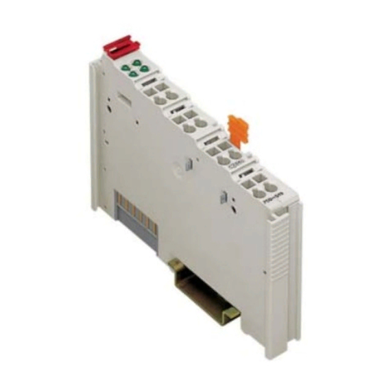
750-532 [4 DO DC 24 V 0,5 A, High-Side Switching, Diagnostics] • 7 View 2 I/O Modules 2.1 Digital Output Modules 2.1.1 750-532 [4 DO DC 24 V 0,5 A, High-Side Switching, Diagnostics] 4 Channel Digital Output Module DC 24 V 0,5 A, 2-conductor, short-circuit-protected; high-side switching, diagnostics 2.1.1.1 View... - Page 8 8 • 750-532 [4 DO DC 24 V 0,5 A, High-Side Switching, Diagnostics] Description The supply voltage for the field side is derived from an adjacent supply module by means of power jumper contacts. The status of the four output channels is each indicated via green status LEDs (DO 1...4).
-
Page 9: Display Elements
750-532 [4 DO DC 24 V 0,5 A, High-Side Switching, Diagnostics] • 9 Display Elements 2.1.1.3 Display Elements Desig- Normal No load is Short Short Over- nation operation, connected circuit circuit tempera- Output with with ture at follows output GND*... -
Page 10: Technical Data
10 • 750-532 [4 DO DC 24 V 0,5 A, High-Side Switching, Diagnostics] Technical Data 2.1.1.5 Technical Data Module specific Data Number of outputs Current consumption (internal) 10 mA max. Voltage via power jumper contacts DC 24 V (-25 % ... +30%) -
Page 11: Process Image
750-532 [4 DO DC 24 V 0,5 A, High-Side Switching, Diagnostics] • 11 Process Image 2.1.1.6 Process Image The output bits control the state of the outputs. Output bit Meaning controls DO 4 controls DO 3 controls DO 2 controls DO 1 –... - Page 12 WAGO Kontakttechnik GmbH & Co. KG Postfach 2880 • D-32385 Minden Hansastraße 27 • D-32423 Minden Phone: 05 71/8 87 – 0 Fax: 05 71/8 87 – 1 69 E-Mail: info@wago.com Internet: http://www.wago.com...
Need help?
Do you have a question about the 750-532 and is the answer not in the manual?
Questions and answers