Table of Contents
Advertisement
Quick Links
Manual
Pos : 2 /D okumentati on allgemein/Ei nband/Ei nband Fronts eite - H andbuc h; CI 2017; mit DocVariablen (Standar d) @ 28\mod_1486477502910_0.doc x @ 405388 @ @ 1
WAGO I/O System 750
750-506(/xxx-xxx)
2DO 24V DC 0.5A/ diagnostics
2-Channel Digital Output; 24 VDC; Short-circuit
Protected; High-side Switching; with Diagnostics
Version 1.2.1
Pos : 3 /Alle Serien (Allgemeine M odul e)/Rec htlic hes, Allgemei nes/Impressum für Standardhandbüc her - allg. Angaben, Ansc hriften, T elefonnummer n und E-Mail-Adres sen @ 3\mod_1219151118203_21.doc x @ 21060 @ @ 1
Public
Advertisement
Chapters
Table of Contents

Related Manuals for WAGO 750-506 Series


Summary of Contents for WAGO 750-506 Series
- Page 1 Manual Pos : 2 /D okumentati on allgemein/Ei nband/Ei nband Fronts eite - H andbuc h; CI 2017; mit DocVariablen (Standar d) @ 28\mod_1486477502910_0.doc x @ 405388 @ @ 1 WAGO I/O System 750 750-506(/xxx-xxx) 2DO 24V DC 0.5A/ diagnostics 2-Channel Digital Output;...
- Page 2 We wish to point out that the software and hardware terms as well as the trademarks of companies used and/or mentioned in the present manual are generally protected by trademark or patent. WAGO is a registered trademark of WAGO Verwaltungsgesellschaft mbH. === Ende der Liste für T extmar ke Ei nband_vorne === Manual Version 1.2.1...
-
Page 3: Table Of Contents
WAGO I/O System 750 Table of Contents 750-506 2DO 24V DC 0.5A/ diagnostics Pos : 5 /D okumentati on allgemein/Verzeic hnisse/Inhalts verz eichnis - Ü berschrift oG und Verzei chnis @ 3\mod_1219151230875_21.doc x @ 21063 @ @ 1 Table of Contents Notes about this Documentation ............. - Page 4 Table of Contents WAGO I/O System 750 750-506 2DO 24V DC 0.5A/ diagnostics 6.2.3 3-Conductor Connection, Ungrounded ..........35 6.2.4 3-Conductor Connection, Grounded ..........35 Using Interference-Free Variants in Safety Related Applications..36 Important Notes ..................37 Connecting to Safety Switching Devices or F I/O Modules ....38 7.2.1...
-
Page 5: Notes About This Documentation
Pos : 13 /Serie 750 ( WAGO I/O SYSTEM)/Hi nweis e z ur D okumentati on (alte Struktur)/Hi nwei se/Ac htung: Hinweis z ur D okumentation I/O-Modul e 750- xxxx @ 4\mod_1237986979656_21.doc x @ 29023 @ @ 1... -
Page 6: Symbols
Notes about this Documentation WAGO I/O System 750 750-506 2DO 24V DC 0.5A/ diagnostics Pos : 14.4 /All e Seri en ( Allgemei ne Module)/Ü bers chriften/Ebene 2/Symbol e - Ü berschrift 2 @ 13\mod_1351068042408_21.doc x @ 105270 @ 2 @ 1 Symbols Pos : 14.5.1 /All e Serien ( Allgemei ne Module)/Sicherheits- und sons tige Hi nweis e/Gefahr/Gefahr: _War nung vor Pers onenschäden allgemei n_ - Erläuter ung @ 13\mod_1343309450020_21.doc x @ 101029 @ @ 1... - Page 7 WAGO I/O System 750 Notes about this Documentation 750-506 2DO 24V DC 0.5A/ diagnostics Additional Information: Refers to additional information which is not an integral part of this documentation (e.g., the Internet). Pos : 14.6 /Dokumentation allgemei n/Glieder ungs elemente/---Seitenwechs el--- @ 3\mod_1221108045078_0.doc x @ 21810 @ @ 1 Manual Version 1.2.1...
-
Page 8: Number Notation
Notes about this Documentation WAGO I/O System 750 750-506 2DO 24V DC 0.5A/ diagnostics Pos : 14.7 /All e Seri en ( Allgemei ne Module)/Ü bers chriften/Ebene 2/D arstellung der Z ahlens ys teme - Ü bers chrift 2 @ 23\mod_1435647128078_21.doc x @ 184811 @ 2 @ 1 Number Notation Pos : 14.8 /All e Seri en ( Allgemei ne Module)/R ec htliches , Allgemei nes /Zahlens ysteme @ 3\mod_1221059454015_21.doc x @ 21711 @ @ 1... -
Page 9: Important Notes
Provisions Pos : 17.6 /Serie 750 (WAGO I/O SYSTEM)/Wic htige Erläuterungen (al te Str uktur)/Bes timmungsgemäß e Ver wendung/Besti mmungsgemäße Ver wendung 750- xxxx für Geräte, UL61010 STD mit EN 61000- 6-3 @ 3\mod_1224064151234_21.doc x @ 24070 @ @ 1... -
Page 10: Technical Condition Of Specified Devices
These modules contain no parts that can be serviced or repaired by the user. The following actions will result in the exclusion of liability on the part of WAGO Kontakttechnik GmbH & Co. KG: •... -
Page 11: Packaging
WAGO I/O System 750 Important Notes 750-506 2DO 24V DC 0.5A/ diagnostics Environmentally friendly disposal benefits health and protects the environment from harmful substances in electrical and electronic equipment. • Observe national and local regulations for the disposal of electrical and electronic equipment. -
Page 12: Safety Advice (Precautions)
Always adhere to the EMC directives applicable to your application. Pos : 17.14.1 /Serie 750 ( WAGO I/O SYST EM)/Ansc hließ en/Ei ns peis ekonzepte/Achtung: Sys temvers orgung nur mi t geeigneter Absic her ung! - UL 61010 - @ 32\mod_1535966317803_21.doc x @ 498058 @ @ 1 Manual Version 1.2.1... - Page 13 Pos : 17.14.4 /Serie 750 ( WAGO I/O SYST EM)/Wichtige Erläuter ung en (alte Struktur)/Sic her heits- und s onstige Hi nweis e/Ac htung/Ac htung: Maxi maler Summenstr om Datenkontakte (5 V) @ 33\mod_1542028658977_21.doc x @ 507951 @ @ 1...
- Page 14 Important Notes WAGO I/O System 750 750-506 2DO 24V DC 0.5A/ diagnostics Replace defective or damaged devices! Replace defective or damaged device/module (e.g., in the event of deformed contacts). Pos : 17.14.7 /Alle Serien (Allgemeine M odul e)/Sic herheits- und s onstige Hinweise/Achtung/Ac htung: Geräte vor kriec henden und isoli erenden Stoffen sc hützen! @ 6\mod_1260181036216_21.doc x @ 46747 @ @ 1...
-
Page 15: Device Description
Pos : 20.5 /Serie 750 (WAGO I/O SYSTEM)/Ger ätebesc hrei bung (al te Str uktur)/Ei nleitung/I/O-Besc hrei bung/Allgemein/Ver weis auf Kapi tel " Ger äte anschli eßen" > "Ansc hluss beispi el(e)" @ 5\mod_1246015203281_21.doc x @ 36298 @ @ 1... - Page 16 Pos : 20.17 /Serie 750 ( WAGO I/O SYST EM)/Wichtige Erläuter ung en (alte Struktur)/Sic her hei ts- und s onstige Hi nweise/Warnung/War nung: Eins atz Variante /xxx-8xx in sic her heitsgerichteten Anwendungen @ 5\mod_1246882860453_21.doc...
-
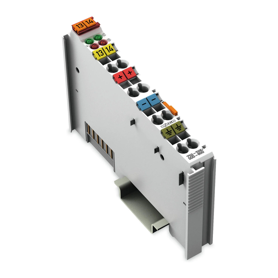
Page 17: View
Figure 1: View Pos : 24 /Serie 750 ( WAGO I/O SYSTEM)/Ger ätebesc hrei bung (al te Str uktur)/Ansic ht/Ansicht C ageClamp® _Legende mit LEDs , mit 1 Entriegel ungslasc he @ 15\mod_1370867188922_21.doc x @ 122225 @ @ 1 Table 4: Legend for Figure “View”... -
Page 18: Connectors
Pos : 28.3 /Serie 750 (WAGO I/O SYSTEM)/Wic htige Erläuterungen (al te Str uktur)/Sic herheits- und sonstige Hinweis e/Achtung/Ac htung: ESD - Auf Potenti alausgleic h der U mgebung achten! @ 32\mod_1539077262331_21.doc x @ 504433 @ @ 1... -
Page 19: Power Jumper Contacts/Field Supply
Power Jumper Contacts/Field Supply Pos : 31.1 /Serie 750 (WAGO I/O SYSTEM)/Wic htige Erläuterungen (al te Str uktur)/Sic herheits- und sonstige Hinweis e/Vorsic ht/Vorsic ht: Verletz ungsgefahr durc h sc harfkantige M ess er kontakte! @ 6\mod_1256193279401_21.doc x @ 43414 @ @ 1 Risk of injury due to sharp-edged blade contacts! The blade contacts are sharp-edged. - Page 20 Device Description WAGO I/O System 750 750-506 2DO 24V DC 0.5A/ diagnostics Do not exceed maximum values via power contacts! The maximum current that can flow through the power jumper contacts is 10 A. The power jumper contacts can be damaged and the permissible operating temperature can be exceeded by higher current values.
-
Page 21: Cage Clamp
Pos : 34 /Serie 750 ( WAGO I/O SYSTEM)/Ger ätebesc hrei bung (al te Str uktur)/Ansc hlüsse/DO/Ansc hlüs se 750- 05xx 2 D O 4- Leiter direkt (DO, 24 V, 0 V, Er de) @ 18\mod_1389620358531_21.doc... -
Page 22: Display Elements
Display Elements Pos : 37 /Serie 750 ( WAGO I/O SYSTEM)/Ger ätebesc hrei bung (al te Str uktur)/Anz eigeelemente/DO/Anzeigeel emente 750-05xx 2 DO ( Agn, Brt, Cgn, Drt) mit Di ag. @ 18\mod_1389770761299_21.doc x @ 141838 @ @ 1 Figure 5: Display Elements Table 7: Legend for Figure “Display Elements”... -
Page 23: Schematic Diagram
Pos : 39 /All e Seri en (Allgemei ne Module)/Ü berschriften/Ebene 2/Sc hematis ches Sc haltbild - Ü bersc hrift 2 @ 4\mod_1240984441312_21.doc x @ 31967 @ 2 @ 1 Schematic Diagram Pos : 40 /Serie 750 ( WAGO I/O SYSTEM)/Ger ätebesc hrei bung (al te Str uktur)/Schematische Sc hal tbil der/D O/Schematisc hes Schaltbild 750- 0506 @ 11\mod_1321958248035_21.doc x @ 83476 @ @ 1 Figure 6: Schematic Diagram Pos : 41 /D okumentation allgemei n/Glieder ungs elemente/---Seitenwechs el--- @ 3\mod_1221108045078_0.doc x @ 21810 @ @ 1... -
Page 24: Technical Data
Pos : 42 /All e Seri en (Allgemei ne Module)/Ü berschriften/Ebene 2/Tec hnische D aten - Ü bersc hrift 2 @ 3\mod_1232967587687_21.doc x @ 26924 @ 2 @ 1 Technical Data Pos : 43 /Serie 750 ( WAGO I/O SYSTEM)/Ger ätebesc hrei bung (al te Str uktur)/T echnisc he Daten/D O/T ec hnisc he D aten 750- 0506 @ 11\mod_1321960902875_21.doc x @ 83498 @ 3333 @ 1 3.5.1 Device Data Table 8: Technical Data ‒... -
Page 25: Connection Type
Connection Type Pos : 45.2 /Serie 750 (WAGO I/O SYSTEM)/Ger ätebesc hrei bung (al te Str uktur)/Technisc he Daten/Anschl uss tec hni k/T echnisc he D aten Verdrahtungsebene CC - 0,08 bis 2,5mm2 @ 17\mod_1380121238809_21.doc x @ 132780 @ @ 1 Table 12: Technical Data –... -
Page 26: Approvals
Pos : 53 /Serie 750 ( WAGO I/O SYSTEM)/Ger ätebesc hrei bung (al te Str uktur)/Z ulass ungen/Ex/Z ulass ungen I/O-Modul 750- xxxx Ex, Standar dversi on und alle Varianten - Einl eitung @ 4\mod_1239099781531_21.doc... -
Page 27: Standards And Guidelines
Pos : 57 /Serie 750 ( WAGO I/O SYSTEM)/Ger ätebesc hrei bung (al te Str uktur)/Nor men und Ric htlini en/EM V-Nor men I/O-Modul 750- xxxx, ohne Vari antenangabe - Einl eitung @ 4\mod_1242803944015_21.doc x @ 33642 @ @ 1... -
Page 28: Process Image
Process Image Pos : 62 /Serie 750 ( WAGO I/O SYSTEM)/Proz ess abbild Lokalbus/Hinweis: Proz ess abbil dmappi ng abhängig von F BK/PFC , ohne Status-/Contr olbyte @ 6\mod_1256126797251_21.doc x @ 43340 @ @ 1 Mapping of process data in the process image of fieldbus systems The representation of the process data of some I/O modules or their variants in the process image depends on the fieldbus coupler/controller used. -
Page 29: Mounting
Pos : 66.2 /Serie 750 (WAGO I/O SYSTEM)/Wic htige Erläuterungen (al te Str uktur)/Sic herheits- und sonstige Hinweis e/Vorsic ht/Vorsic ht: Verletz ungsgefahr durc h sc harfkantige M ess er kontakte! @ 6\mod_1256193279401_21.doc x @ 43414 @ @ 1 Risk of injury due to sharp-edged blade contacts! The blade contacts are sharp-edged. -
Page 30: Mounting Sequence
I/O modules with fewer power contacts. Pos : 66.8 /Serie 750 (WAGO I/O SYSTEM)/Wic htige Erläuterungen (al te Str uktur)/Sic herheits- und sonstige Hinweis e/Achtung/Ac htung: I/O-Module nur in vorg esehener R eihenfolge stec ken! @ 6\mod_1256194177073_21.doc x @ 43429 @ @ 1 Insert I/O modules only from the proper direction! All I/O modules feature grooves for power jumper contacts on the right side. -
Page 31: Removing The I/O Module
(if any) to the head station or to the preceding and, if applicable, following I/O module are established. Pos : 66.12 /Serie 750 ( WAGO I/O SYST EM)/Monti eren/D emonti eren/I/O-M odul entfernen (neutrales 3D) @ 35\mod_1561382848176_21.doc x @ 548874 @ 3 @ 1 5.2.2 Removing the I/O Module Remove the I/O module from the assembly by pulling the release tab. -
Page 32: Figure 9: Removing The I/O Module (Example)
Mounting WAGO I/O System 750 750-506 2DO 24V DC 0.5A/ diagnostics Figure 9: Removing the I/O Module (Example) Electrical connections for data or power jumper contacts are disconnected when removing the I/O module. Pos : 67 /D okumentation allgemei n/Glieder ungs elemente/---Seitenwechs el--- @ 3\mod_1221108045078_0.doc x @ 21810 @ @ 1 Manual Version 1.2.1... -
Page 33: Connect Devices
Connect Devices Pos : 69 /Serie 750 ( WAGO I/O SYSTEM)/Anschli eßen/Leiter an C AGE C LAM P ans chli eßen ( allgemei n) - Ü bersc hrift 2 und Text @ 3\mod_1225448660171_21.doc x @ 24928 @ 2 @ 1 Connecting a Conductor to the CAGE CLAMP ®... -
Page 34: Connection Examples
Pos : 71 /All e Seri en (Allgemei ne Module)/Ü berschriften/Ebene 2/Ansc hluss beispi ele - Übersc hrift 2 @ 4\mod_1240996036328_21.doc x @ 32010 @ 2 @ 1 Connection Examples Pos : 72 /Serie 750 ( WAGO I/O SYSTEM)/Anschli eßen/Anschl uss beispi ele/Digitalausgänge/Ansc hlus sbeis piele 750-05xx_2D O_2L_3L_mit Er de @ 18\mod_1389692158254_21.doc x @ 141688 @ 3333 @ 1 6.2.1... -
Page 35: 3-Conductor Connection, Ungrounded
WAGO I/O System 750 Connect Devices 750-506 2DO 24V DC 0.5A/ diagnostics 6.2.3 3-Conductor Connection, Ungrounded Figure 13: Connecting Diagram, 3-Conductor Connection, Ungrounded 6.2.4 3-Conductor Connection, Grounded Figure 14: Connecting Diagram, 3-Conductor Connection, Grounded Pos : 73 /D okumentation allgemei n/Glieder ungs elemente/---Seitenwechs el--- @ 3\mod_1221108045078_0.doc x @ 21810 @ @ 1 Manual Version 1.2.1... -
Page 36: Using Interference-Free Variants In Safety Related Applications
750-506 2DO 24V DC 0.5A/ diagnostics Pos : 74.1 /Serie 750 (WAGO I/O SYSTEM)/Eins atz in sicherheitsg erichteten Anwendung en/Ei nleitung - rüc kwir kungsfr eie Varianten @ 6\mod_1258973563064_21.doc x @ 44681 @ 1 @ 1 Using Interference-Free Variants in Safety Related Applications The variant 750-506/xxx-8xx of the I/O module 750-506 (designation “... -
Page 37: Important Notes
750-506 2DO 24V DC 0.5A/ diagnostics Pos : 74.4 /Serie 750 (WAGO I/O SYSTEM)/Eins atz in sicherheitsg erichteten Anwendung en/Hinweise zum Ei ns atz i n Sicherheits anwendungen @ 6\mod_1258974811438_21.doc x @ 44688 @ 2 @ 1 Eins atz der rüc kwir kungsfrei en Digital ausg angs kl emme in Sic her heitsanwendungen... -
Page 38: Connecting To Safety Switching Devices Or F I/O Modules
Pos : 74.5 /Dokumentation allgemei n/Glieder ungs elemente/---Seitenwechs el--- @ 3\mod_1221108045078_0.doc x @ 21810 @ @ 1 Pos : 74.6 /Serie 750 (WAGO I/O SYSTEM)/Eins atz in sicherheitsg erichteten Anwendung en/Allgemeiner Aufbau ei ner Potentialgruppe - r üc kwir kungsfr eie Varianten @ 6\mod_1258973074755_21.doc x @ 44664 @ 23 @ 1... -
Page 39: Examples Of Connection
750-506 2DO 24V DC 0.5A/ diagnostics Pos : 76 /Serie 750 ( WAGO I/O SYSTEM)/Eins atz in sicherheitsg erichteten Anwendung en/Ansc hlus sbeispi ele/Ansc hlussbeis piel 2/4-Kanal-Digital ausg angs kl emmen i n Sicherheits anwendungen @ 6\mod_1259219930757_21.doc x @ 45290 @ 3 @ 1 Eins atz der rüc kwir kungsfrei en Digital ausg angs kl emme in Sic her heitsanwendungen... -
Page 40: Use In Hazardous Environments
Use in Hazardous Environments Pos : 78.2 /Serie 750 (WAGO I/O SYSTEM)/Eins atz in Ex- Ber eichen/Ei ns atz ber eic h Serie 750 @ 3\mod_1234272230203_21.doc x @ 27500 @ @ 1 The WAGO I/O System 750 (electrical equipment) is designed for use in Zone 2 hazardous areas and shall be used in accordance with the marking and installation regulations. -
Page 41: Marking Configuration Examples
Marking for Europe According to ATEX and IECEx Pos : 78.6 /Serie 750 (WAGO I/O SYSTEM)/Eins atz in Ex- Ber eichen/Beis piel bedruc kung ATEX und IEC Ex_TUEV07_2019 @ 35\mod_1568102068939_21.doc x @ 559059 @ @ 1 Figure 18: Marking Example per ATEX and IECEx Figure 19: Text Detail –... -
Page 42: Table 18: Description Of The Marking Example Per Atex And Iecex
Use in Hazardous Environments WAGO I/O System 750 750-506 2DO 24V DC 0.5A/ diagnostics Table 18: Description of the Marking Example per ATEX and IECEx Marking Text Description TUEV 07 ATEX 554086 X Approving authority or certificate numbers IECEx TUN 09.0001 X... -
Page 43: Figure 20: Marking Example Of An Approved I/O Module Ex I Per Atex And
750-506 2DO 24V DC 0.5A/ diagnostics Pos : 78.8 /Serie 750 (WAGO I/O SYSTEM)/Eins atz in Ex- Ber eichen/Beis piel bedruc kung ATEX und IEC Ex_TUEV12_Ex i_2019 @ 35\mod_1568102226939_21.doc x @ 559063 @ @ 1 Figure 20: Marking Example of an Approved I/O Module Ex i per ATEX and IECEx Figure 21: Text Detail –... -
Page 44: Table 19: Description Of The Marking Example Of An Approved I/O Module Ex I Per Atex And Iecex
Use in Hazardous Environments WAGO I/O System 750 750-506 2DO 24V DC 0.5A/ diagnostics Table 19: Description of the Marking Example of an Approved I/O Module Ex i per ATEX and IECEx Marking Text Description TUEV 12 ATEX 106032 X... -
Page 45: Marking For The United States Of America (Nec) And Canada (Cec)
Figure 22: Marking Example According to NEC Pos : 78.11 /Serie 750 ( WAGO I/O SYST EM)/Ei ns atz i n Ex-Bereic hen/Beispi elbedruc kung und T extdetail N EC 500_2017 @ 14\mod_1360580302684_21.doc x @ 111353 @ @ 1 Figure 23: Text Detail – Marking Example According to NEC 500... -
Page 46: Figure 24: Text Detail - Marking Example For Approved I/O Module Ex I
750-506 2DO 24V DC 0.5A/ diagnostics Pos : 78.13 /Serie 750 ( WAGO I/O SYST EM)/Ei ns atz i n Ex-Bereic hen/Beispi elbedruc kung und T extdetail N EC 505_2017 @ 29\mod_1497865583500_21.doc x @ 424739 @ @ 1 Figure 24: Text Detail – Marking Example for Approved I/O Module Ex i According to NEC 505... -
Page 47: Figure 26: Text Detail - Marking Example For Approved I/O Module Ex I
750-506 2DO 24V DC 0.5A/ diagnostics Pos : 78.16 /Serie 750 ( WAGO I/O SYST EM)/Ei ns atz i n Ex-Bereic hen/Beispi elbedruc kung und T extdetail C EC_2017 @ 29\mod_1497865583297_21.doc x @ 424736 @ @ 1 Figure 26: Text Detail – Marking Example for Approved I/O Module Ex i According to CEC 18... -
Page 48: Installation Regulations
Special Notes including Explosion Protection Pos : 78.21.2 /Serie 750 ( WAGO I/O SYST EM)/Ei ns atz i n Ex-Bereic hen/Besonder e Hi nweis e einschli eßlich Explosionssc hutz _2017 @ 29\mod_1491556994025_21.doc x @ 415448 @ @ 1 The following warning notices are to be posted in the immediately proximity of the WAGO I/O System 750 (hereinafter “product”):... - Page 49 WAGO I/O System 750 Use in Hazardous Environments 750-506 2DO 24V DC 0.5A/ diagnostics Explosive atmosphere occurring simultaneously with assembly, installation or repair work must be ruled out. Among other things, these include the following activities • Insertion and removal of components •...
-
Page 50: Special Notes Regarding Ul Hazardous Location
Special Notes Regarding UL Hazardous Location Pos : 78.21.5 /Serie 750 ( WAGO I/O SYST EM)/Ei ns atz i n Ex-Bereic hen/U L H az ardous Locati on gemäß U L Fil e E198726_2019 @ 35\mod_1564473955786_21.doc x @ 555668 @ @ 1 For UL Hazardous Location acc. -
Page 51: List Of Figures
WAGO I/O System 750 List of Figures 750-506 2DO 24V DC 0.5A/ diagnostics Pos : 80 /D okumentation allgemei n/Verz eic hniss e/Abbil dungs verz eic hnis - Übersc hrift oG und Verz eichnis @ 3\mod_1219222916765_21.doc x @ 21080 @ @ 1 List of Figures Figure 1: View ....................17... -
Page 52: List Of Tables
List of Tables WAGO I/O System 750 750-506 2DO 24V DC 0.5A/ diagnostics Pos : 82 /D okumentation allgemei n/Verz eic hniss e/Tabell enverz eichnis - Übersc hrift oG und Verz eichnis @ 3\mod_1219222958703_21.doc x @ 21084 @ @ 1 List of Tables Table 1: Variants .................... - Page 53 WAGO I/O System 750 750-506 2DO 24V DC 0.5A/ diagnostics Pos : 84 /D okumentation allgemei n/Einband/Einband - Leers eite für durc h 2 teilbare Seitenz ahl (Standarddruc k) @ 3\mod_1219230851078_0.doc x @ 21123 @ @ 1 Manual Version 1.2.1...
- Page 54 Pos : 85 /D okumentation allgemei n/Einband/Einband R üc ks eite - alle D okumente; CI 2017 @ 28\mod_1486477503580_21.doc x @ 405394 @ @ 1 WAGO Kontakttechnik GmbH & Co. KG Postfach 2880 • D - 32385 Minden Hansastraße 27 • D - 32423 Minden Phone: +49 571 887 –...
Need help?
Do you have a question about the 750-506 Series and is the answer not in the manual?
Questions and answers