
Related Manuals for WAGO 750-502


Summary of Contents for WAGO 750-502
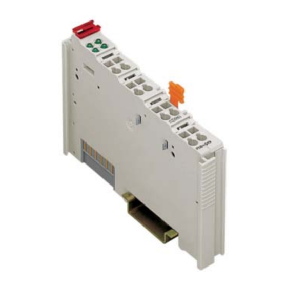
- Page 1 Fieldbus Independent I/O Modules 2 DO AC/DC 230 V SSR, 0.3 A 750-509 Manual Version 1.0.3...
- Page 2 • General Copyright © 2006 by WAGO Kontakttechnik GmbH & Co. KG All rights reserved. WAGO Kontakttechnik GmbH & Co. KG Hansastraße 27 D-32423 Minden Phone: +49 (0) 571/8 87 – 0 Fax: +49 (0) 571/8 87 – 1 69 E-Mail: info@wago.com...
-
Page 3: Table Of Contents
750-509 [2 DO AC/DC 230 V SSR, 0.3 A] ........7 2.1.1.1 View....................7 2.1.1.2 Description..................7 2.1.1.3 Display Elements ................8 2.1.1.4 Schematic Diagram................. 9 2.1.1.5 Technical Data ................9 2.1.1.6 Process Image ................10 2.1.2 Contact Protective Circuit for Relay Modules ........11 WAGO-I/O-SYSTEM 750 I/O Modules... -
Page 4: Important Comments
WAGO Kontakttechnik GmbH & Co. KG declines all liability resulting from improper action and damage to WAGO products and third party products due to non-observance of the information contained in this manual. -
Page 5: Symbols
Routines or advice for efficient use of the device and software optimization. More information References on additional literature, manuals, data sheets and INTERNET pages 1.3 Number Notation Number Code Example Note Decimal normal notation Hexadecimal 0x64 C notation Binary '100' Within ', '0110.0100' Nibble separated with dots WAGO-I/O-SYSTEM 750 I/O Modules... -
Page 6: Safety Notes
1.5 Scope This manual describes the Digital Output Module 750-509 2 DO AC/DC 230 V SSR, 0.3 A of the modular WAGO-I/O-SYSTEM 750. Handling, assembly and start-up are described in the manual of the Fieldbus Coupler. Therefore this documentation is valid only in the connection with the appropriate manual. -
Page 7: O Modules
230 V) is connected to each terminal of the relay and is fed in via the internal power jumper contacts of an adjacent supply module. By closing a relay, the field power applied is switched to the second relay connection of signal output DO1 or DO2. WAGO-I/O-SYSTEM 750 I/O Modules... -
Page 8: Display Elements
Examples of protection circuits can be seen in the section 2.1.2 "Contact Protective Circuit for Relay Modules". The output module 750-509 can be used with all couplers/controllers of the WAGO-I/O-SYSTEM 750. 2.1.1.3 Display Elements Channel... -
Page 9: Schematic Diagram
*2,5 kV rated surge voltage overvoltage category III Internal bit width 2 bit out Dimensions (mm) W x H x L 12 x 64* x 100 * from upper edge of 35 DIN rail Weight ca. 55 g WAGO-I/O-SYSTEM 750 I/O Modules... -
Page 10: Process Image
II 3 G EEx nC II C T4 Conformity Marking More Information Detailed references to the approvals are listed in the document "Overview Approvals WAGO-I/O-SYSTEM 750", which you can find on the CD ROM ELECTRONICC Tools and Docs (Item-No.: 0888-0412) or in the internet under: www.wago.com... -
Page 11: Contact Protective Circuit For Relay Modules
- attenuation only above g051214e Advantages: R/C combination - HF attenuation via power storage - suitable for A.C. voltage medium to - level-independent Load short attenuation Disadvantages: - exact dimensioning re- g051215e quired - high inrush current WAGO-I/O-SYSTEM 750 I/O Modules... - Page 12 WAGO Kontakttechnik GmbH & Co. KG Postfach 2880 • D-32385 Minden Hansastraße 27 • D-32423 Minden Phone: 05 71/8 87 – 0 Fax: 05 71/8 87 – 1 69 E-Mail: info@wago.com Internet: http://www.wago.com...
Need help?
Do you have a question about the 750-502 and is the answer not in the manual?
Questions and answers