
Related Manuals for WAGO 750-597


Summary of Contents for WAGO 750-597
- Page 1 Manual WAGO I/O SYSTEM 750 750-597 8AO 0-10V/±10V DC 8-Channel Analog Output; 0 ... 10 V/±10 V Version 1.2.0...
- Page 2 We wish to point out that the software and hardware terms as well as the trademarks of companies used and/or mentioned in the present manual are generally protected by trademark or patent. WAGO is a registered trademark of WAGO Verwaltungsgesellschaft mbH. Manual Version 1.2.0...
- Page 3 WAGO I/O SYSTEM 750 Table of Contents 750-597 8AO 0-10V/±10V DC Table of Contents Notes about this Documentation ............. 6 Validity of this Documentation..............6 Copyright ....................6 Symbols ....................7 Number Notation ..................9 Font Conventions ................... 9 Important Notes ..................10 Legal Bases ..................
- Page 4 Table of Contents WAGO I/O SYSTEM 750 750-597 8AO 0-10V/±10V DC 4.3.3.2 Two's Complement Representation ..........36 Mounting ....................37 Mounting Sequence ................37 Inserting and Removing Devices ............38 5.2.1 Inserting the I/O Module ..............38 5.2.2 Removing the I/O Module ..............39 Connect Devices ..................
- Page 5 WAGO I/O SYSTEM 750 Table of Contents 750-597 8AO 0-10V/±10V DC 10.1.1.1 PROFIBUS DP Fieldbus Coupler/Controller 750-333(/0xx-000), 750-833(/0xx-000) ........76 10.1.1.2 PROFINET IO Fieldbus Coupler 750-370, 750-375(/025-000), 750-377(/025-000)........76 10.1.2 Parameterization 8 AI 0-10 V, ±10 V DC S.E........77 10.1.2.1...
- Page 6 This documentation is only applicable to the I/O module 750-597 (8AO 0-10V/±10V DC). The I/O module 750-597 shall only be installed and operated according to the instructions in this manual and in the manual for the used fieldbus coupler or controller.
- Page 7 WAGO I/O SYSTEM 750 Table of Contents 750-597 8AO 0-10V/±10V DC Symbols Personal Injury! Indicates a high-risk, imminently hazardous situation which, if not avoided, will result in death or serious injury. Personal Injury Caused by Electric Current! Indicates a high-risk, imminently hazardous situation which, if not avoided, will result in death or serious injury.
- Page 8 Table of Contents WAGO I/O SYSTEM 750 750-597 8AO 0-10V/±10V DC Additional Information: Refers to additional information which is not an integral part of this documentation (e.g., the Internet). Manual Version 1.2.0...
-
Page 9: Table 1: Number Notation
WAGO I/O SYSTEM 750 Table of Contents 750-597 8AO 0-10V/±10V DC Number Notation Table 1: Number Notation Number Code Example Note Decimal Normal notation Hexadecimal 0x64 C notation Binary '100' In quotation marks, nibble separated '0110.0100' with dots (.) Font Conventions... - Page 10 2.1.1 Subject to Changes WAGO Kontakttechnik GmbH & Co. KG reserves the right to provide for any alterations or modifications. WAGO Kontakttechnik GmbH & Co. KG owns all rights arising from the granting of patents or from the legal protection of utility patents.
- Page 11 These modules contain no parts that can be serviced or repaired by the user. The following actions will result in the exclusion of liability on the part of WAGO Kontakttechnik GmbH & Co. KG: •...
- Page 12 Table of Contents WAGO I/O SYSTEM 750 750-597 8AO 0-10V/±10V DC Environmentally friendly disposal benefits health and protects the environment from harmful substances in electrical and electronic equipment. • Observe national and local regulations for the disposal of electrical and electronic equipment.
- Page 13 Always adhere to the EMC directives applicable to your application. Power from SELV/PELV power supply only! All field signals and field supplies connected to this I/O module (750-597) must be powered from SELV/PELV power supply(s)! Manual Version 1.2.0...
- Page 14 Table of Contents WAGO I/O SYSTEM 750 750-597 8AO 0-10V/±10V DC Do not switch off the system supply to the local bus during operation! The I/O module’s output is powered by the 24 VDC field supply. For I/O modules up to HW Version 01: If the 5 VDC system supply or the local bus and other field supply fails, voltages >...
- Page 15 WAGO I/O SYSTEM 750 Table of Contents 750-597 8AO 0-10V/±10V DC Do not use any contact spray! Do not use any contact spray. The spray may impair contact area functionality in connection with contamination. Do not reverse the polarity of connection lines! Avoid reverse polarity of data and power supply lines, as this may damage the devices involved.
- Page 16 Power to the internal electronics is supplied via both the internal data bus and the field supply. The I/O module 750-597 (8AO 0-10V/±10V DC) receives the 24 V voltage supply for the field level from an upstream I/O module or from the fieldbus coupler/controller via blade-formed power jumper contacts.
-
Page 17: Table 3: Compatibility List 750-597
WAGO I/O SYSTEM 750 Table of Contents 750-597 8AO 0-10V/±10V DC Table 3: Compatibility List 750-597 Firmware Bus System Fieldbus Couplers/Controllers Item No. Revision Status 750-375 PROFINET Fieldbus coupler 750-377 Fieldbus coupler 750-333 PROFIBUS Programmable fieldbus controller 750-833 750-342 Fieldbus coupler... - Page 18 Table of Contents WAGO I/O SYSTEM 750 750-597 8AO 0-10V/±10V DC The 750-597 I/O module cannot be operated on the following fieldbus couplers: • 750-320 • 750-323 • 750-324 • 750-327 • 750-343 • 750-351 Manual Version 1.2.0...
-
Page 19: Figure 1: View Of Device
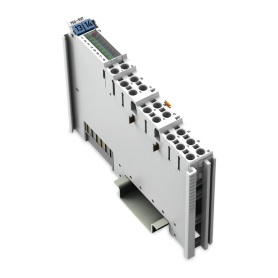
WAGO I/O SYSTEM 750 Table of Contents 750-597 8AO 0-10V/±10V DC View Figure 1: View of Device Table 4: Legend for Figure “View” Pos. Description Details See Section Marking possibility with Mini- “Device Description” > “Display Elements” Status LEDs “Device Description” > “Connectors”... -
Page 20: Figure 2: Data Contacts
Table of Contents WAGO I/O SYSTEM 750 750-597 8AO 0-10V/±10V DC Connectors 3.2.1 Data Contacts/Local Bus Communication between the fieldbus coupler/controller and the I/O modules as well as the system supply of the I/O modules is carried out via the local bus. The contacting for the local bus consists of 6 data contacts, which are available as self-cleaning gold spring contacts. -
Page 21: Figure 3: Power Jumper Contacts
The blade contacts are sharp-edged. Handle the I/O module carefully to prevent injury. Do not touch the blade contacts. The I/O module 750-597 has 2 self-cleaning power jumper contacts that supply and transmit power for the field side. The contacts on the left side of the I/O module are designed as blade contacts and those on the right side as spring contacts. -
Page 22: Figure 4: Push-In Cage Clamp
Table of Contents WAGO I/O SYSTEM 750 750-597 8AO 0-10V/±10V DC Use supply modules for ground (earth)! The I/O module has no power jumper contacts for receiving and transmitting the earth potential. Use a supply module when an earth potential is needed for the subsequent I/O modules. -
Page 23: Table 6: Legend For The "Push-In Cage Clamp
WAGO I/O SYSTEM 750 Table of Contents 750-597 8AO 0-10V/±10V DC ® Table 6: Legend for the “Push-in CAGE CLAMP Connections” – 8-Channel, 2-Wire Channel Designation Connection Function Analog output 1: Signal Common Ground 0V ground potential Analog output 2: Signal... -
Page 24: Figure 5: Display Elements
Table of Contents WAGO I/O SYSTEM 750 750-597 8AO 0-10V/±10V DC Display Elements Figure 5: Display Elements Table 7: Legend for Figure “Display Elements” Channel Designation LED State Function Not ready for operation or no/faulty local bus communication Function AO1... -
Page 25: Figure 6: Schematic Diagram
WAGO I/O SYSTEM 750 Table of Contents 750-597 8AO 0-10V/±10V DC Operating Elements The I/O module 750-597 has no operating elements. Schematic Diagram Figure 6: Schematic Diagram Manual Version 1.2.0... -
Page 26: Table 8: Technical Data - Device
Table of Contents WAGO I/O SYSTEM 750 750-597 8AO 0-10V/±10V DC Technical Data 3.6.1 Device Data Table 8: Technical Data — Device Width 12 mm Height (from top edge of DIN rail) 64 mm Depth 100 mm Weight 50 g 3.6.2... -
Page 27: Table 11: Technical Data - Outputs
WAGO I/O SYSTEM 750 Table of Contents 750-597 8AO 0-10V/±10V DC 3.6.4 Outputs Table 11: Technical Data – Outputs No. of outputs 8 (short-circuit-protected) Signal connection 2-wire connection −10 … +10 V Signal voltage 0 … 10 V −11 … +11 V Signal voltage max. -
Page 28: Table 15: Technical Data - Climatic Environmental Conditions
Table of Contents WAGO I/O SYSTEM 750 750-597 8AO 0-10V/±10V DC 3.6.6 Climatic Environmental Conditions Table 15: Technical Data – Climatic Environmental Conditions Surrounding air temperature, operation 0 °C … 55 °C −25 °C … +85 °C Surrounding air temperature, storage 0 …... - Page 29 Locations UL 61010-2-201 Korea Certification MSIP-REM-W43-AOM750 The following Ex approvals have been granted to 750-597 I/O modules: TÜV 07 ATEX 554086 X I M2 Ex d I Mb II 3 G Ex nA IIC T4 Gc II 3 D Ex tc IIIC T135°C Dc IECEx TUN 09.0001 X...
- Page 30 “I/O Modules” included in the description concerning the process image of the corresponding coupler/controller. The 750-597 I/O module provides 1 status byte (8 bit) and 1 data word (16 bit) per channel. The digitized process value is output in a data word via the process image of the fieldbus coupler/controller as output byte “0”...
-
Page 31: Table 16: Process Image - I/O Module 750-597
Presentation of control/status bytes a function of fieldbus coupler/controller! The I/O module always makes a complete process image incl. control/status bytes available to the fieldbus coupler/controller. The WAGO-I/O-CHECK startup tool accesses the startup process image. The fieldbus coupler/controller uses a different process image, in which display of control/status bytes can be supported, to stage cyclic process data via the fieldbus. -
Page 32: Table 17: Status Byte Ch1_S0
Table of Contents WAGO I/O SYSTEM 750 750-597 8AO 0-10V/±10V DC Status Bytes The status byte for channel 1 displays the diagnoses “Undervoltage field supply” and “General Error”. Table 17: Status Byte CH1_S0 Status byte CH1_S0, Byte 0 Bit 7... - Page 33 WAGO I/O SYSTEM 750 Table of Contents 750-597 8AO 0-10V/±10V DC Process Data 4.3.1 Overview of Signal Types The following table serves as an overview of all supported signal types. The following sections contain detailed information about the individual signal types.
-
Page 34: Table 19: Process Image, Signal Type "0-10 V", Amount/Sign Format
Table of Contents WAGO I/O SYSTEM 750 750-597 8AO 0-10V/±10V DC Signal Type “0-10 V”, ID0 4.3.2 4.3.2.1 Amount/Sign Format For the power supply with signal type “0-10 V”, the numerical range of 0x0000 … 0x7FFF is scaled to the output voltage range of 0 V … +10 V. -
Page 35: Table 21: Process Image, Signal Type
WAGO I/O SYSTEM 750 Table of Contents 750-597 8AO 0-10V/±10V DC Signal Type “+/- 10 V”, ID1 4.3.3 4.3.3.1 Amount/Sign Format For the power supply with signal type “+/− 10 V”, the numerical range of 0xFFFF … 0x7FFF is scaled to the output voltage range of −10 V … +10 V. -
Page 36: Table 22: Process Image, Signal Type "+/−10 V", Two's Complement Representation
Table of Contents WAGO I/O SYSTEM 750 750-597 8AO 0-10V/±10V DC 4.3.3.2 Two's Complement Representation For the power supply with signal type “+/− 10 V”, the numerical range of 0x8000 … 0x7FFF is scaled to the output voltage range of −10 V … +10 V. - Page 37 Always plug a bus end module (750-600) onto the end of the fieldbus node! You must always use a bus end module at all fieldbus nodes with WAGO I/O SYSTEM 750 fieldbus couplers or controllers to guarantee proper data transfer.
-
Page 38: Figure 7: Insert I/O Module (Example)
Table of Contents WAGO I/O SYSTEM 750 750-597 8AO 0-10V/±10V DC Inserting and Removing Devices Do not work when devices are energized! High voltage can cause electric shock or burns. Switch off all power to the device prior to performing any installation, repair or maintenance work. -
Page 39: Figure 9: Removing The I/O Module (Example)
WAGO I/O SYSTEM 750 Table of Contents 750-597 8AO 0-10V/±10V DC 5.2.2 Removing the I/O Module Remove the I/O module from the assembly by pulling the release tab. Figure 9: Removing the I/O Module (Example) Electrical connections for data or power jumper contacts are disconnected when removing the I/O module. -
Page 40: Figure 10: Connecting A Conductor To A Push-In Cage Clamp
Do not connect more than one conductor at one single connection! If more than one conductor must be routed to one connection, these must be connected in an up-circuit wiring assembly, for example using WAGO feed- through terminals. Terminate both solid and stranded or ferruled conductors by simply pushing them ®... -
Page 41: Figure 11: Connection Example - 2-Wire Connection
WAGO I/O SYSTEM 750 Table of Contents 750-597 8AO 0-10V/±10V DC Connection Example Use shielded signal lines! Only use shielded signal lines for analog signals and I/O modules which are equipped with shield clamps. Only then can you ensure that the accuracy and interference immunity specified for the respective I/O module can be achieved even in the presence of interference acting on the signal cable. - Page 42 Calibration of channels and adjustment of analog outputs • Monitoring WAGO-I/O-CHECK You can obtain the WAGO-I/O-CHECK software on a CD under Item No. 759- 302. This CD contains all the application program files and an explanation. You can find a description at the internet page at http://www.wago.com...
-
Page 43: Figure 12: Wago-I/O-Check User Interface
WAGO I/O SYSTEM 750 Table of Contents 750-597 8AO 0-10V/±10V DC To open specific parameterization dialogs for the I/O module 750-597, proceed as follows: If enabled, disable Monitor or Control mode. Click the respective button in the toolbar, so that it is no longer highlighted. -
Page 44: Figure 13: Display Of Process Data
Table of Contents WAGO I/O SYSTEM 750 750-597 8AO 0-10V/±10V DC To display the process date for the configured 750-597 I/O module, proceed as follows: Click the I/O module and then the Process data button. Right-click on the I/O module and then click the Process data menu item (see figure). -
Page 45: Figure 14: Parameterization Dialog For The I/O Module 750-597
Table of Contents 750-597 8AO 0-10V/±10V DC 7.1.1 Parameterization Dialog The parameterization dialog is divided into the following areas: Figure 14: Parameterization Dialog for the I/O Module 750-597 Title bar Horizontal tab menu Main menu Vertical tab menu Display range... -
Page 46: Figure 15: Title Bar In The Parameterization Dialog
Table of Contents WAGO I/O SYSTEM 750 750-597 8AO 0-10V/±10V DC 7.1.1.1 Title Bar The title bar in the parameterization dialog contains the program icon, a window title and buttons for exiting, minimizing and maximizing the application window. Figure 15: Title Bar in the Parameterization Dialog... -
Page 47: Figure 16: Horizontal Tab Menu
WAGO I/O SYSTEM 750 Table of Contents 750-597 8AO 0-10V/±10V DC 7.1.1.3 Horizontal Tab Menu The horizontal tab menu contains the following tabs: Figure 16: Horizontal Tab Menu Click one of the tabs to display the respective selection options in the main menu. -
Page 48: Table 24: Buttons In The Application Menu
7.1.1.3.1.1 Only open parameter files created with WAGO-I/O-CHECK! Please note that only parameter files created with WAGO-I/O-CHECK can be opened. The parameter files have the extension *.ao. In this menu item you can open and load an existing parameter file. Proceed as follows: 1. -
Page 49: Figure 18: Contents Of The Horizontal Tab Start
WAGO I/O SYSTEM 750 Table of Contents 750-597 8AO 0-10V/±10V DC “Save” Menu Item 7.1.1.3.1.2 The calibration settings are not saved! Please note that the calibration settings cannot be saved in the parameter file. Note the memory range! Please note that only the settings are saved in the parameter file that you have... -
Page 50: Figure 19: Start > Main Menu > Channel Selection List
Table of Contents WAGO I/O SYSTEM 750 750-597 8AO 0-10V/±10V DC Figure 19: Start > Main Menu > Channel Selection List The exact meaning of the individual selection options is described in the “Main Menu” section. 7.1.1.3.3 “Connection” Tab Click the Connection tab in the horizontal tab menu to display the following selection options in the main menu. -
Page 51: Figure 22: Overview Of The Vertical Tab Menu
WAGO I/O SYSTEM 750 Table of Contents 750-597 8AO 0-10V/±10V DC Figure 22: Overview of the Vertical Tab Menu Click one of the menu items to call up the related parameterization options in the display area. The exact meaning of the individual selection options is described in the following sections. -
Page 52: Figure 23: Module Settings Menu Item View
Table of Contents WAGO I/O SYSTEM 750 750-597 8AO 0-10V/±10V DC 7.1.1.4.1 “Module settings” Menu Item Save settings! Click the [Write] or [Write all button to write any settings you have made to the I/O module. Figure 23: Module settings Menu Item View... -
Page 53: Figure 24: Channel Settings Menu Item View
WAGO I/O SYSTEM 750 Table of Contents 750-597 8AO 0-10V/±10V DC 7.1.1.4.2 “Channel settings” Menu Item Save settings! Click the [Write] or [Write all button to write any settings you have made to the I/O module. Figure 24: Channel settings Menu Item View... -
Page 54: Figure 25: Scaling Menu Item View
Table of Contents WAGO I/O SYSTEM 750 750-597 8AO 0-10V/±10V DC 7.1.1.4.3 “Scaling” Menu Item Save settings! Click the [Write] or [Write all button to write any settings you have made to the I/O module. Selecting the scaling method! If user scaling is enabled, enabling or disabling manufacturer scaling has no effect. -
Page 55: Table 27: Scaling Menu Item
WAGO I/O SYSTEM 750 Table of Contents 750-597 8AO 0-10V/±10V DC Table 27: Scaling Menu Item Option Description Channel x Manufacturer scaling is enabled (no scaling of Gain and Offset). Manufacturer scaling is disabled (no scaling of Gain and Offset). -
Page 56: Figure 26: Calibration Menu Item View
Table of Contents WAGO I/O SYSTEM 750 750-597 8AO 0-10V/±10V DC 7.1.1.4.4 “Calibration” Menu Item Save settings! Click the [Write] or [Write all button to write any settings you have made to the I/O module. Figure 26: Calibration Menu Item View Manual Version 1.2.0... -
Page 57: Table 28: Calibration Menu Item
WAGO I/O SYSTEM 750 Table of Contents 750-597 8AO 0-10V/±10V DC Table 28: Calibration Menu Item Option Description Enable factory configuration Factory calibration is enabled and user calibration is disabled. Enable Factory calibration is disabled and user calibration is enabled. -
Page 58: Figure 27: Process Value Menu Item View
Table of Contents WAGO I/O SYSTEM 750 750-597 8AO 0-10V/±10V DC 7.1.1.4.5 “Process Value” Menu Item In this area, an overview of all I/O module channels and the respective process value are displayed. Save settings! Click the [Write] or [Write all button to write any settings you have made to the I/O module. -
Page 59: Figure 28: Information Menu Item View
WAGO I/O SYSTEM 750 Table of Contents 750-597 8AO 0-10V/±10V DC 7.1.1.4.6 “Information” Menu Item This area provides an overview of the specifications for the I/O module used. You obtain information about the following points: • Article number • Description •... -
Page 60: Figure 29: Expanding The Status Messages Window
Table of Contents WAGO I/O SYSTEM 750 750-597 8AO 0-10V/±10V DC 7.1.1.6 Status Messages This area provides information about occurring undervoltages of the field supply. A requirement for displaying status message is that the checkbox for the “Enable diagnostic functions globally” function is activated in the Module Settings menu item. -
Page 61: Table 31: Signal Types
WAGO I/O SYSTEM 750 Table of Contents 750-597 8AO 0-10V/±10V DC Calibrating Process Values Manufacturer calibration serves to compensate for tolerances in electrical components of the I/O module. User calibration allows you to compensate for the tolerances of electrical components of both the I/O module and connected devices and to take into account factors such as component age and different ambient temperatures at the installation site. - Page 62 = y1 – (m × x1) b = 1 V − (0.99 × 0.97 V) = 0.04 V 10. Enter the calculated gain value (“0.99”) in WAGO-I/O-CHECK. 11. Convert the result for the calibration offset based on the process value resolution: 0.04 V / 0.000305 V per digit = 131 digit...
-
Page 63: Table 33: Variable Legend - Scaling Process Values
WAGO I/O SYSTEM 750 Table of Contents 750-597 8AO 0-10V/±10V DC Scaling Process Values User scaling allows you to scale the process value application specific with the following voltage ranges by means of parameterizing the Gain and Offset values: •... - Page 64 The response of the I/O module if a diagnostic is present depends on the configuration. You can enable or disabled these diagnostics separately in WAGO-I/O-CHECK (see section “Startup” > … > “Parameterization with WAGO- I/O-CHECK”). The I/O module allows a field supply undervoltage to be displayed. A dedicated bit in the status byte for channel 1 is assigned to the error for the entire module.
- Page 65 Table of Contents 750-597 8AO 0-10V/±10V DC Use in Hazardous Environments The WAGO I/O SYSTEM 750 (electrical equipment) is designed for use in Zone 2 hazardous areas and shall be used in accordance with the marking and installation regulations. The following sections include both the general identification of components (devices) and the installation regulations to be observed.
-
Page 66: Figure 31: Marking Example Per Atex And Iecex
Table of Contents WAGO I/O SYSTEM 750 750-597 8AO 0-10V/±10V DC Marking Configuration Examples 9.1.1 Marking for Europe According to ATEX and IECEx Figure 31: Marking Example per ATEX and IECEx Figure 32: Text Detail – Marking Example per ATEX and IECEx Manual Version 1.2.0... -
Page 67: Table 34: Description Of The Marking Example Per Atex And Iecex
WAGO I/O SYSTEM 750 Table of Contents 750-597 8AO 0-10V/±10V DC Table 34: Description of the Marking Example per ATEX and IECEx Marking Text Description TUEV 07 ATEX 554086 X Approving authority or certificate numbers IECEx TUN 09.0001 X Dust... -
Page 68: Figure 33: Marking Example Of An Approved I/O Module Ex I Per Atex And Iecex
Table of Contents WAGO I/O SYSTEM 750 750-597 8AO 0-10V/±10V DC Figure 33: Marking Example of an Approved I/O Module Ex i per ATEX and IECEx Figure 34: Text Detail – Marking Example of an Approved I/O Module Ex i... -
Page 69: Table 35: Description Of The Marking Example Of An Approved I/O Module Ex I Per Atex And Iecex
WAGO I/O SYSTEM 750 Table of Contents 750-597 8AO 0-10V/±10V DC Table 35: Description of the Marking Example of an Approved I/O Module Ex i per ATEX and IECEx Marking Text Description TUEV 12 ATEX 106032 X Approving authority or... -
Page 70: Figure 35: Marking Example According To Nec
Table of Contents WAGO I/O SYSTEM 750 750-597 8AO 0-10V/±10V DC 9.1.2 Marking for the United States of America (NEC) and Canada (CEC) Figure 35: Marking Example According to NEC Figure 36: Text Detail – Marking Example According to NEC 500... -
Page 71: Figure 37: Text Detail - Marking Example For Approved
WAGO I/O SYSTEM 750 Table of Contents 750-597 8AO 0-10V/±10V DC Figure 37: Text Detail – Marking Example for Approved Ex i I/O Module According to NEC 505 Table 37: Description of Marking Example for Approved Ex i I/O Module According to NEC 505... -
Page 72: Figure 39: Text Detail - Marking Example For Approved
Table of Contents WAGO I/O SYSTEM 750 750-597 8AO 0-10V/±10V DC Figure 39: Text Detail – Marking Example for Approved Ex i I/O Modules According to CEC 18 attachment J Table 39: Description of Marking Example for Approved Ex i I/O Modules According to CEC 18... - Page 73 Special Notes including Explosion Protection The following warning notices are to be posted in the immediately proximity of the WAGO I/O SYSTEM 750 (hereinafter “product”): WARNING – DO NOT REMOVE OR REPLACE FUSED WHILE ENERGIZED! WARNING – DO NOT DISCONNECT WHILE ENERGIZED! WARNING –...
- Page 74 Table of Contents WAGO I/O SYSTEM 750 750-597 8AO 0-10V/±10V DC Explosive atmosphere occurring simultaneously with assembly, installation or repair work must be ruled out. Among other things, these include the following activities • Insertion and removal of components •...
- Page 75 WAGO I/O SYSTEM 750 Table of Contents 750-597 8AO 0-10V/±10V DC 9.2.2 Special Notes Regarding UL Hazardous Location For UL Hazardous Location acc. to UL File E198726, the following additional requirements apply: • Use in Class I, Division 2, Group A, B, C, D or non-hazardous areas only •...
-
Page 76: Table 40: Configuration Profibus Dp
Table of Contents WAGO I/O SYSTEM 750 750-597 8AO 0-10V/±10V DC Appendix 10.1 Configuration and Parameterization using a GSD File with PROFIBUS DP and PROFINET IO 10.1.1 Configuration 8 AO 0-10 V, ±10 V DC S.E. 10.1.1.1 PROFIBUS DP Fieldbus Coupler/Controller... -
Page 77: Figure 40: Example Of The Profibus Dp Fieldbus Coupler Parameterization Dialog
WAGO I/O SYSTEM 750 Table of Contents 750-597 8AO 0-10V/±10V DC 10.1.2 Parameterization 8 AI 0-10 V, ±10 V DC S.E. The GSD file can be used to provide the I/O module on the PROFIBUS DP and PROFINET IO fieldbus coupler with all operating parameters. - Page 78 Table of Contents WAGO I/O SYSTEM 750 750-597 8AO 0-10V/±10V DC Figure 42: Example of the 750-370 fieldbus coupler parameterization dialog part 2 Figure 43: Example of the 750-375(/025-000) and 750-377(/025-000) fieldbus coupler parameterization dialog part 1 Manual Version 1.2.0...
-
Page 79: Table 43: Specific Module / Channel Parameters For 750-597
All PROFIBUS DP and PROFINET IO Fieldbus Couplers The following assignment applies to the parameters of the I/O module when using PROFIBUS DP and PROFINET IO fieldbus devices. Table 43: Specific module / channel parameters for 750-597 GSD File WAGO-I/O-CHECK... -
Page 80: Table 44: General Module / Channel Parameters
Table of Contents WAGO I/O SYSTEM 750 750-597 8AO 0-10V/±10V DC 10.1.2.2 PROFIBUS DP Fieldbus Coupler 750-333(/0xx-000), 750-833(/0xx-000) The aforementioned fieldbus couplers or controllers allow module-specific parameterization of diagnosis behavior as well as channel-specific parameterization of a substitute value. Table 44: General module / channel parameters... -
Page 81: Table 45: General Module / Channel Parameters
WAGO I/O SYSTEM 750 Table of Contents 750-597 8AO 0-10V/±10V DC 10.1.2.3 PROFINET IO Fieldbus Coupler 750-370 The aforementioned fieldbus coupler allows module-specific parameterization of diagnosis and the substitute value behavior of the outputs as well as channel- specific parameterization of the process data representation and the output substitute value. -
Page 82: Table 46: General Module / Channel Parameters
Table of Contents WAGO I/O SYSTEM 750 750-597 8AO 0-10V/±10V DC 10.1.2.4 PROFINET IO Fieldbus Coupler 750-375(/025-000), 750-377(/025-000) The aforementioned fieldbus couplers allow module-specific parameterization of behavior at diagnosis. Table 46: General module / channel parameters Parameter Value Explanation An undervoltage of the I/O module’s field side power supply... -
Page 83: Table Of Contents
Figure 11: Connection Example – 2-Wire Connection ........41 Figure 12: WAGO-I/O-CHECK User Interface ............43 Figure 13: Display of Process Data ..............44 Figure 14: Parameterization Dialog for the I/O Module 750-597 ......45 Figure 15: Title Bar in the Parameterization Dialog ..........46 Figure 16: Horizontal Tab Menu .................47 Figure 17: Buttons in the Application Menu ............47... - Page 84 List of Figures WAGO I/O SYSTEM 750 750-597 8AO 0-10V/±10V DC Figure 41: Example of the 750-370 fieldbus coupler parameterization dialog part 1 ..............77 Figure 42: Example of the 750-370 fieldbus coupler parameterization dialog part 2 ..............78 Figure 43: Example of the 750-375(/025-000) and 750-377(/025-000) fieldbus coupler parameterization dialog part 1 ...78...
- Page 85 Table 13: Technical Data – Power Jumper Contacts ..........27 Table 14: Technical Data – Data Contacts ............27 Table 15: Technical Data – Climatic Environmental Conditions ......28 Table 16: Process Image – I/O Module 750-597 ..........31 Table 17: Status Byte CH1_S0 ................32 Table 18: Status Byte CH2_S1 ................32 Table 19: Process Image, Signal Type “0-10 V”,...
- Page 86 Table 40: Configuration PROFIBUS DP .............76 Table 41: Configuration 750-370 ................76 Table 42: Configuration 750-375(/025-000), 750-377(/025-000) ......76 Table 43: Specific module / channel parameters for 750-597 ......79 Table 44: General module / channel parameters ..........80 Table 45: General module / channel parameters ..........81 Table 46: General module / channel parameters ..........82...
- Page 87 WAGO I/O SYSTEM 750 List of Tables 750-597 8AO 0-10V/±10V DC Manual Version 1.2.0...
- Page 88 WAGO Kontakttechnik GmbH & Co. KG • Postfach 2880 D - 32385 Minden Hansastraße 27 • D - 32423 Minden +49 571 887 – 0 Phone: +49 571 887 – 844169 Fax: E-Mail: info@wago.com Internet: www.wago.com...
Need help?
Do you have a question about the 750-597 and is the answer not in the manual?
Questions and answers