
Related Manuals for FujiFilm PB-30


Summary of Contents for FujiFilm PB-30
- Page 1 English フジノン和文 Balloon Controller PB-30 OPERATION MANUAL (Ver. 1.0*) Thank you for purchasing our product. Read this manual carefully before use to avoid unexpected accidents and to take full advantage of the product’s capabilities.
-
Page 2: Important Safety Information
Important Safety Information Important Safety Information 1. Intended Use This product is a device to feed air to or evacuate a balloon that assists insertion of an endoscope into the small intestine at a medical facility under the management of a physi- cian. - Page 3 Foreign substance or liquid may cause fire or electric shock if it enters inside of this product. In such a case, stop using the equipment immediately, disconnect the power plug from the power outlet, and contact your local FUJIFILM dealer. 8. If Any Abnormality Occurs During Clinical Procedure If any abnormality occurs with the equipment or any error code is indicated, refer to Chapter 12 “Troubleshooting.”...
-
Page 4: Table Of Contents
5.1 Outline ..................26 5.2 Graphic Display ................26 Chapter 6 Preparation and Inspection ..............28 6.1 Connecting PB-30 and an External Monitor ........29 6.2 Attaching the Filter and Tube ............29 6.3 Installation of PB-30 ..............34 6.4 Connecting PB-30 and the Endoscope .........36 6.5 Inspecting PB-30 ................38... - Page 5 Contents Chapter 8 Cleaning ....................51 8.1 Conditions of Cleaning ..............51 8.2 Necessary Equipment and Materials ..........52 8.3 Cleaning..................53 Chapter 9 Chemical Disinfection ................55 9.1 Methods of Chemical Disinfection..........55 9.2 Conditions of Disinfection ............56 9.3 Chemical Disinfection of Balloon ..........57 9.4 Disinfection of Tube Kit...............59 Chapter 10 Sterilization ...................61 10.1 Methods of Sterilization ...............61 10.2 Sterilizing Tube Kit ..............62...
-
Page 6: Preface
Preface Preface This manual describes how to use the balloon controller PB-30 as well as how to clean, disinfect, sterilize and store it. PB-30 is used in combination with an endoscope for G.I. tract. For details on how to use it, refer to the operation manual of each endoscope. -
Page 7: Chapter 1 Safety
Chapter 1 Safety Chapter 1 Safety 1. Precautions in Using the Product 1) Preparation and inspection before use Prior to using this product, prepare a spare one to avoid unexpected accidents such as equipment failure. If a replacement is not available, you may not be able to continue endoscopic procedures. - Page 8 Chapter 1 Safety 5) Electromagnetic interference This equipment has been tested and found to comply with the limits for medical devices defined in EN 60601-1-2:2007. These limits are designed to provide reasonable protection against harmful interference in a typical medical installation. However, it is possible that it may cause harmful interference to other devices in the vicinity, even though it is installed and used in accordance with the instructions.
- Page 9 4. “ Warning” and “ Caution” Messages Appearing in Individual Chapters Chapter 6 Preparation and Inspection 6.1 Connecting PB-30 and an External Monitor If an external monitor is used, connect the power cable to receptacles for peripherals on the cart or a receptacle via an insulating transformer. Not doing so may increase the enclosure leakage current, posing a risk of injury or electric shock to the patient and/or the physician when he/she comes into contact with those devices.
- Page 10 Chapter 1 Safety Chapter 8 Cleaning 8.1 Conditions of Cleaning Clean and sterilize (or disinfect) this product properly according to the procedures described in this manual, immediately after an examination is completed. There is a risk of infection and/or damaging this product. Chapter 9 Chemical Disinfection 9.3 Chemical Disinfection of Balloon The balloon must be completely immersed in chemical solution.
-
Page 11: Chapter 2 Composition Of Pb-30 And System Configuration
Chapter 2 Composition of PB-30 and System Configuration Chapter 2 Composition of PB-30 and System Configuration 2.1 Composition of PB-30 The PB-30 set consists of the following items. [Note] Figures in parentheses indicate quantities. Main unit PB-30 (1) Power Cord (1) -
Page 12: System Configuration
Chapter 2 Composition of PB-30 and System Configuration 2.2 System Configuration The balloon controller is used in combination with the applicable endoscope and over-tube. [Note] Refer to “<Devices Used in Combination>” in “Main Specifications” for the combinations of endoscopes, over-tubes and tube kits. -
Page 13: Chapter 3 Name And Function Of Each Part
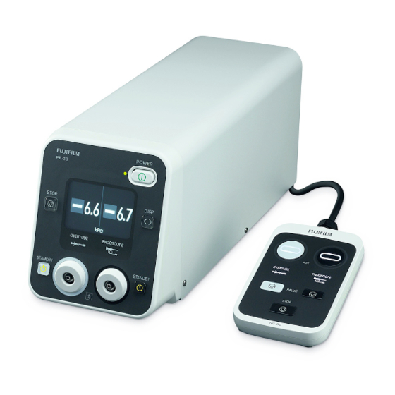
Chapter 3 Name and Function of Each Part Chapter 3 Name and Function of Each Part Main Unit (PB-30) <Front Panel> Power button This switch is used to turn on/off the power. When the power is on, the green LED on the left side is lit. - Page 14 Chapter 3 Name and Function of Each Part Tube connector 2 (Endoscope side) The tube 2 is connected to this part through the filter of the tube kit. Tube connector 1 (Over-tube side) The tube 1 is connected to this part through the filter of the tube kit. Balloon switch 1 (White: Over-tube side) This switch is used to start/stop supplying air to or discharging air from the balloon on the over-tube side.
- Page 15 Chapter 3 Name and Function of Each Part <Back Panel> Remote terminal The cable of the remote switch is connected to this terminal. S video terminal A component signal separated into a Y signal for brightness and a C signal for color is output.
- Page 16 Chapter 3 Name and Function of Each Part Foot switch terminal This terminal is used to connect the foot switch (optional accessory). RS232C connector Service personnel use this connector for maintenance and inspection. Normally, this connector is not used. Fuse holder One T2.5A H 250V fuse is contained in each holder. Power cord Equipotential terminal The equipotential plug is connected to this terminal.
-
Page 17: Remote Switch (Rc-30)
Chapter 3 Name and Function of Each Part 3.2 Remote Switch (RC-30) 3.2.1 Name and Function of Each Part of Remote Switch Toggle switch 1 (White: Over-tube side) This switch toggles between air supply and air discharge to/from the balloon on the over-tube side. When the power is turned on, the inside light turns on and air is discharged from the balloon. - Page 18 Chapter 3 Name and Function of Each Part Toggle switch 2 (Black: Endoscope side) This switch toggles between air supply and air discharge to/from the balloon on the endoscope side. When the power is turned on, the inside light turns on and air is discharged from the balloon.
- Page 19 Chapter 3 Name and Function of Each Part 3.2.2 Operation of Remote Swtich Switch operation Switch state Air supply or discharge Air is discharged from the balloon or over-tube. Inside light: On Power-on [Note] When the power is turned on, both the Outside light: Off toggle switches 1 and 2 are set to air discharge.
-
Page 20: Tube Kit [Note] Optional Accessory
Chapter 3 Name and Function of Each Part 3.3 Tube Kit [Note] Optional Accessory [Note] Use the tube kit in combination with the devices in “Main Specifications”. [Note] The filter and tube are consumable supplies. Replace them with new once a month or once every 10 cases, whichever comes first. - Page 21 Chapter 3 Name and Function of Each Part 3.3.2 TY-400 and TY-500 TY-400 [Note] Optional accessory TY-500 [Note] Optional accessory Filter If the balloon is broken, body fluid that flows backwards is trapped here. Rubber plate This plate integrates the tubes to prevent cross connection of the tube on the over-tube side and that on the endoscope side.
-
Page 22: Foot Switch (Fs1) [Note] Optional Accessory
Chapter 3 Name and Function of Each Part 3.4 Foot Switch (FS1) [Note] Optional Accessory Gray switch (Gray) This switch is used to supply or discharge air to/from the balloon on the over-tube side. When the power is turned on, air is discharged from the balloon. When this switch is pressed once, air is supplied to the balloon. -
Page 23: Symbols
Chapter 3 Name and Function of Each Part 3.5 Symbols Symbol Description Lot number Serial number Date of manufacture Manufacturer Authorised representative in the European Community Consult instructions for use Temperature limitation Keep dry CE marking Type BF applied part WEEE marking [Note] Humidity limitation Atmospheric pressure limitation... -
Page 24: Chapter 4 Pressure Display
Chapter 4 Pressure Display Chapter 4 Pressure Display 4.1 Outline The status of the balloon on the endoscope or over-tube connected to the tube connector is displayed on the pressure display on the front panel of the main unit. Two types of pressure display are available: pressure value display and pressure indicator display. -
Page 25: Pressure Indicator Display
Chapter 4 Pressure Display 4.3 Pressure Indicator Display The status of the balloon on the endoscope or over-tube connected to the tube connector is displayed with the pressure indicator. The pressure indicator of the tube connector 1 (over-tube side) is displayed on the left side, and that of the tube connector 2 (endoscope side) is displayed on the right side. -
Page 26: Chapter 5 Graphic Display
Chapter 5 Graphic Display Chapter 5 Graphic Display 5.1 Outline The status of the balloon on the endoscope or over-tube connected to the tube connector is displayed graphically on the monitor. The status of the balloon connected to the tube can be displayed graphically by connecting the video output terminal on the back panel of the main unit and an NTSC monitor. - Page 27 Chapter 5 Graphic Display 5.2.1 List of Graphic Displays Status Display Description Air discharge The pressure in the balloon is -6.0 kPa or stopped lower. Air discharge in Air discharge from the balloon is in progress progress. Air discharge from the balloon is paused Air discharge with the pause switch on the remote paused...
-
Page 28: Chapter 6 Preparation And Inspection
Connect the filter and tube to the main unit. "6.2.1 Inspecting the Filter and Tube" "6.2.3 Connecting the Filter and Tube to the Main Unit" Install PB-30 onto the cart and connect the remote "6.3 Installation of PB-30" switch. Connect PB-30 and the endoscope. -
Page 29: Connecting Pb-30 And An External Monitor
Connect the external monitor in accordance with the specification of the insulating transformer. Connect PB-30 and an external monitor with a cable. PB-30 External monitor For the S video terminal For the video output terminal 6.2 Attaching the Filter and Tube... - Page 30 Chapter 6 Preparation and Inspection 6.2.1 Inspecting the Filter and Tube (1) Clean and disinfect (or sterilize) the filter and tube of the tube kit in accordance with Chapter 8 “Cleaning” and Chapter 10 “Sterilization.” (2) Make sure that there is no irregularity such as a flaw or deformation in the appearance of the filter and tube.
- Page 31 Chapter 6 Preparation and Inspection 6.2.2 Connection Between PB-30 and Tube [Note] Use the tube kit in combination with the devices in“Main Specifications”. <Tube Connection (TY-04)> Tube 1 Tube 2 <Tube Connection (TY-06)> Tube 1 Tube 2...
- Page 32 Chapter 6 Preparation and Inspection <Tube Connection (TY-400)> Tube 1 Tube 2 <Tube Connection (TY-500)> Tube 1 Tube 2...
- Page 33 Chapter 6 Preparation and Inspection 6.2.3 Connecting the Filter and Tube to the Main Unit (1) Attach a filter on each tube connector. Hold the outer side of the filter and turn clockwise to attach. (2) Connect the tube to the attached filter. <In the case of TY-04 and TY-06>...
-
Page 34: Installation Of Pb-30
Chapter 6 Preparation and Inspection 6.3 Installation of PB-30 WARNING Use the power source at the rated voltage. Only use the power cord provided with this product. Improper use of power may cause electric shock or fire. Connect the power plug to the protective earth receptacle. Do not set up this product in locations where there is any risk of contact with water. - Page 35 Chapter 6 Preparation and Inspection CAUTION Do not close the vent holes. Otherwise, the instrument may get overheated. Install this product in a flat place where there is no vibration or shock. If not installed, it may fall down or be broken. Use the power source at the rated voltage.
-
Page 36: Connecting Pb-30 And The Endoscope
(7) Insert the power plug of this product into the peripheral receptacle on the cart. 6.4 Connecting PB-30 and the Endoscope [Note] For details on how to attach the over-tube and the balloon, refer to the operation manual of the over-tube and that of endoscope. - Page 37 Chapter 6 Preparation and Inspection (3) Connect the the tube 1 (over-tube side) of the tube kit to the over-tube. <In the case of TY-04 and TY-06> Connect the connector of the tube to the balloon air feed inlet of the over-tube. In case of TY-04 and TY-06 <In the case of TY-400 and TY-500>...
-
Page 38: Inspecting Pb-30
Chapter 6 Preparation and Inspection 6.5 Inspecting PB-30 6.5.1 Inspecting the Functions of the Pump and the Balloon (1) Turn on the power switch. The power switch lights up and self-diagnosis starts. If there is no abnormality, the balloon switch lights up in green and air is discharged from the channel on the over-tube side and that on the endoscope side. - Page 39 Chapter 6 Preparation and Inspection (4) Press the toggle switch 1 once again. Make sure that the inside light lights up and the balloon deflates. (5) Put the end of the over-tube into water. Press the toggle switch 1 to inflate the balloon by supplying air. Make sure that there is no air leakage by putting the end of the over-tube into water.
- Page 40 Chapter 6 Preparation and Inspection (8) Press the toggle switch 2 once again. Make sure that the inside light lights up and the balloon deflates. (9) Inflate the balloon again and make sure that there is no air leakage by putting the end of the endoscope into water. After confirmation, press the toggle switch 2 to deflate the balloon by discharging air.
- Page 41 Chapter 6 Preparation and Inspection (3) Make sure that the indications on the pressure indicator 1 and 2 are stable at about -6 kPa. (4) Wrap the balloon on the over-tube lightly with your hand. (5) Press the toggle switch 1 of the remote switch to supply air.
- Page 42 Chapter 6 Preparation and Inspection (7) Press the toggle switch 1 once again to deflate the balloon by discharging air. (8) Wrap the balloon on the endoscope lightly with your hand. (9) Press the toggle switch 2 of the remote switch to supply air.
- Page 43 Chapter 6 Preparation and Inspection (11) Press the toggle switch 2 once again to deflate the balloon by discharging air.
-
Page 44: Installation And Operation Of Foot Switch
Chapter 6 Preparation and Inspection 6.6 Installation and Operation of Foot Switch The balloon can be controlled with the optional foot switch (FS1) connected to the foot switch terminal. Connect the connector of the foot switch (FS1) to the foot switch terminal of the main unit. -
Page 45: Chapter 7 How To Use The Equipment
Chapter 7 How to Use the Equipment Chapter 7 How to Use the Equipment This chapter outlines how to operate this product according to the general procedures. 7.1 Operating the Balloon CAUTION Do not operate the balloon forcibly. Doing so may damage mucous membrane. - Page 46 Chapter 7 How to Use the Equipment (2) If the balloon is inflated and the pressure inside the channel reaches +5.6 kPa, air supply is adjusted automatically to keep the balloon inflated. <Supplying Air into the Balloon on the Over-tube> (1) Press the toggle switch 1 on the remote switch.
- Page 47 Chapter 7 How to Use the Equipment <Discharging Air from the Balloon on the Over-tube> (1) Press the toggle switch 1 of the remote switch. The inside light lights up and air is discharged from the balloon on the over-tube side. (2) If the balloon is deflated and the pressure inside the channel reaches -6.0 kPa, air discharge is adjusted automatically to keep the balloon deflated.
-
Page 48: Completion Of Examination
Chapter 7 How to Use the Equipment 7.2 Completion of Examination (1) Discharge air from the balloons of the endoscope and over-tube by operating the toggle switch or stop switch. (2) After the balloons are completely deflated, slowly withdraw the endoscope and over-tube. [Note] Withdraw the endoscope after the balloon is completely deflated. -
Page 49: Removing Pb-30
Chapter 7 How to Use the Equipment 7.3 Removing PB-30 Remove the tube kit from the endoscope. <In the case of TY-04 and TY-400> (1) Rotate the tube counterclockwise to disconnect it from the balloon air feed inlet of the endoscope and the over-tube's air feed inlet. - Page 50 Chapter 7 How to Use the Equipment (4) Remove the tube kit and the filter from the main unit of PB-30. [Note] Turn off the power switch before removing the filter and tube from the main unit.
-
Page 51: Chapter 8 Cleaning
FUJIFILM dealer. Refer to the detergent manufacturer's instructions for preparation and use. Personal protective equipment should be worn by end users during reprocessing. Table 8.1 Compatible methods of cleaning for PB-30 and consumable supplies Chemical cleaning Ultrasonic cleaning... -
Page 52: Necessary Equipment And Materials
Chapter 8 Cleaning 8.2 Necessary Equipment and Materials Prepare the necessary equipment. Sterile gauze Syringe Personal protective equipment. Rubber gloves Goggles Mask Protective clothing Cleaning fluid Container for cleaning fluid... -
Page 53: Cleaning
Chapter 8 Cleaning 8.3 Cleaning 8.3.1 Cleaning Tube Kit (1) Fill a basin with fresh cleaning fluid prepared according to the cleaning fluid manufacturer’s recommendations to completely immerse the tube kit. (2) Immerse the entire tube kit in the cleaning fluid. (3) Clean the surface of the tube kit in the cleaning fluid using a clean lint-free cloth. - Page 54 Chapter 8 Cleaning (7) Remove the tube kit from the cleaning fluid. (8) Inject air with a syringe into the tube kit to purge the cleaning fluid. (9) Fill a basin with potable water to completely immerse the tube kit. (10) Soak the tube kit in the potable water, and rinse it while gently shaking.
-
Page 55: Chapter 9 Chemical Disinfection
Chapter 9 Chemical Disinfection 9.1 Methods of Chemical Disinfection Prior to disinfection, cleaning should be performed according to Section 8.3. Table 9.1 Compatible methods of cleaning, disinfection and sterilization for PB-30 and consumable supplies Method of cleaning Method of disinfection and sterilization... -
Page 56: Conditions Of Disinfection
Legally marketed 2.4 to 3.5% glutaraldehyde solutions can be used with the tube and balloon for disinfection when used in accordance with the manufacturer’s instructions. Contact your local FUJIFILM dealer for names of compatible glutaraldehyde solutions. Refer to the chemical solution manufacturer’s instructions regarding preparation, use and exposure conditions. -
Page 57: Chemical Disinfection Of Balloon
Chapter 9 Chemical Disinfection 9.3 Chemical Disinfection of Balloon WARNING The balloon must be completely immersed in a chemical solution. Remove air bubbles completely. If any air bubbles remain, effective disinfection cannot be achieved and an inadequately balloon may pose an infection risk. - Page 58 Chapter 9 Chemical Disinfection (8) Keep the balloon immersed in the chemical solution in accordance with the temperature, concentration and time recommended by the chemical solution manufacturer, and cover the basin to prevent the vaporization of the chemical solution. [Note] Confirm that no potions of the balloon fold over onto itself which may prevent contact of balloon surfaces with the chemical solution.
-
Page 59: Disinfection Of Tube Kit
Chapter 9 Chemical Disinfection 9.4 Disinfection of Tube Kit WARNING The tube kit must be completely immersed in a chemical solution. Remove air bubbles completely. If any air bubbles remain, effective disinfection cannot be achieved and an inadequately disinfected tube kit may pose an infection risk. - Page 60 Chapter 9 Chemical Disinfection (9) Soak the tube kit in sterile water, and rinse it well while gently shaking. (10) Flush sterile water into the tube kit to rinse inside of it. (11) Repeat steps (9) and (10) two more times for a total of 3 rinses.
-
Page 61: Chapter 10 Sterilization
10.1 Methods of Sterilization The tube kit can be sterilized with a pre-vacuum steam sterilizer. To ensure effective sterilization, carry out cleaning carefully before autoclaving. Table 10.1 Compatible methods of cleaning, disinfection and sterilization for PB-30 and consumable supplies Method of cleaning... -
Page 62: Sterilizing Tube Kit
Chapter 10 Sterilization 10.2 Sterilizing Tube Kit [Note] Prior to steam sterilization, ensure that the tube kit has been thoroughly cleaned following the instructions provided. (1) Dry out the tube kit completely. (2) Put the tube kit in a sterile pack, and then seal the sterile pack tightly. -
Page 63: Autoclave
Drying time 20 minutes [Note] The above pre-vacuum steam sterilization (autoclaving) conditions (132°C for 4 minutes) were used in FUJIFILM's validation studies. However, each health care facility should follow the relevant industry standards, facility-specific procedures and sterilizer manufacturer's instructions to ensure the... -
Page 64: Sterilization Of Balloon
Chapter 10 Sterilization 10.4 Sterilization of Balloon WARNING Proceed with gas sterilization after removing moisture from the balloon. Applying gas sterilization to wet surfaces may compromise sterilization. CAUTION Proceed with aeration after gas sterilization. Gas residuals remaining in the balloon after gas sterilization may be harmful to the human body. Use gas sterilization to sterilize the balloon. -
Page 65: Chapter 11 Storage And Maintenance
Chapter 11 Storage and Maintenance Chapter 11 Storage and Maintenance WARNING Dry the tube kit before storing them. If the tube kit is stored without drying it, there is a risk of infection. CAUTION Clean the equipment in the proper way as specified. Do not store the equipment in locations that do not satisfy the storage conditions. -
Page 66: Storage
Chapter 11 Storage and Maintenance 11.2 Storage CAUTION Store in a state in which no force is applied to the tube. Do not store in locations that do not satisfy the storage conditions. Otherwise, equipment failure may occur. Store this product in a location that satisfies the following storage conditions. Sterilize the tube and filter before storing them. -
Page 67: Chapter 12 Troubleshooting
If the problem persists even after taking countermeasures or if the phenomenon is not found in the table below, contact your local FUJIFILM dealer. If the measured pressure and the error code is displayed alternately on the pressure display, refer to “12.3 Error Codes.”... - Page 68 Stop the examination and contact your local FUJIFILM dealer. 2) Faulty filter 2) Replace the filter with a new one. The balloon on the...
- Page 69 Chapter 12 Troubleshooting Air supply to the balloon Software malfunction Remove the tube from the air inlet of the endoscope or air discharge from and over-tube and carry out evacuation manually the balloon cannot be using a syringe. Then, withdraw the endoscope stopped.
-
Page 70: If The Buzzer Sounds
If any of the following conditions occurs, it is considered as an occurrence of an abnormality, which makes the PB-30 buzzer sound. • If the state in which the pressure inside the channel is exceeded +8.2 kPa continues for 5 seconds •... - Page 71 Chapter 12 Troubleshooting < If the pressure does not reach “- 6.0 kPa” within 30 seconds after starting evacuation> Cause : A tube or connector is disconnected. Countermeasure : Press the stop switch to clear the buzzer. The equipment automatically maintains the balloon status.
-
Page 72: Error Codes
Chapter 12 Troubleshooting 12.3 Error Codes If any abnormality occurs, the measured pressure and the error code are displayed alternately on the pressure display. Error code Indication method Possible cause Action to take Alternate indication Tube disconnection Clear the buzzer using the STOP switch. of the error and the detected at power-on Turn the power off, connect the tube and... -
Page 73: Main Specifications
7.0 ± 1.0 kg (main unit), 0.4 kg (remote switch) [Note] Refer to “<Devices Used in Combination>” for the tube kits necessary to connect the applicable endoscope and over-tube. For combinations other than those listed in the section, contact your local FUJIFILM dealer. - Page 74 Main Specifications <Operation Environment> Temperature +10 to +40°C Humidity 30 to 85%RH (no dew condensation) Pressure 70 to 106 kPa (within range of atmospheric pressure) <Storage Environment> Temperature -10 to +45°C Humidity 30 to 95%RH (no dew condensation) Pressure 70 to 106 kPa (within range of atmospheric pressure) <Transport Environment>...
- Page 75 Main Specifications <Medical Device Directive> This product complies with the requirements of European Directive 93/42/EEC. Classification : Class IIa <Electromagnetic Compatibility (EMC) Information> This product is intended for use in the electromagnetic environments specified below. The customer or the user of this product should assure that it is used in such an environment.
- Page 76 Main Specifications Electromagnetic immunity compliance information and guidance Compliance EN 60601-1-2 Immunity test Guidance Test level level Floors should be wood, concrete, or ceramic tile. If floors are Electrostatic discharge (ESD) ± 6kV: contact Same as left covered with synthetic material, ±...
- Page 77 Main Specifications Electromagnetic immunity compliance information and guidance Compliance EN 60601-1-2 Immunity test Guidance Test level level Portable and mobile RF communications equipment should be used no closer to any part of this product, including cables, than the recommended separation distance calculated from the equation applicable to the frequency of the transmitter.
- Page 78 Main Specifications <Specifications of Video Signal> Graphic display out put function Output signal Composite video signal Terminal shape BNC connector S video terminal <Block Diagram> By operating the air feed pump and the evacuating pump in the apparatus, the endoscope balloon and the over-tube balloon are alternately inflated and deflated.
-
Page 79: Warranty And After-Sales Service
If the equipment does not work properly, check it first by reading this manual again and follow all instructions. If the equipment is still not working well, contact your local FUJIFILM dealer. Repairs during the warranty period We will repair your equipment free of charge according to the provisions of the warranty. -
Page 80: Disposal Of Electric And Electronic Equipment
The recycling of materials will help to conserve natural resources. For more detailed information about recycling of this product, contact your local FUJIFILM dealer. In Countries outside the EU: If you wish to discard this product, contact your local... -
Page 81: Index
Index Index <B> <W> Buzzer ..............70 Warning ............2, 6, 9 <C> Caution ............2, 6, 9 Chemical .............. 55 Cleaning ............8, 51 Clinical procedures ..........3 Conventions used in this manual ......6 <E> Equipotential terminal .......... 16 <F>... -
Page 82: Service Centers
Contact our regional representative below or the distributor from which you purchased the product. <Europe> FUJIFILM Europe GmbH http://www.fujifilm.eu/eu/ See our website to locate our representative in your country. <USA> Fujifilm Medical Systems U.S.A., Inc http://www.fujifilmendoscopy.com/ (800) 385-4666 <Australia> FUJIFILM Australia Pty Ltd. http://www.fujifilm.com.au/ 1800 060 209 <Asia>... - Page 83 Service Centers...
- Page 84 FUJIFILM Corporation 26-30, Nishiazabu 2-chome, Minato-ku, Tokyo 106-8620, Japan FUJIFILM Europe GmbH Heesenstrasse 31, 40549 Duesseldorf, Germany EU Importer: FUJIFILM Europe B.V. Oudenstaart 1, 5047 TK Tilburg, The Netherlands 897N120519D 170815 - 5.0 - DT - E2 FV623A Printed in Japan...
Need help?
Do you have a question about the PB-30 and is the answer not in the manual?
Questions and answers