Table of Contents
Advertisement
Advertisement
Table of Contents

Related Manuals for MotorGuide Tour Pro 82


Summary of Contents for MotorGuide Tour Pro 82
- Page 1 Operation Maintenance Installation Warranty Manual...
- Page 3 An official copy of the Declaration of Conformity can be found at www.motorguide.com/us/en/support‑certifications.html. Thank You Thank you for choosing MotorGuide, one of the finest trolling motors available. Years of experience have been committed to the goal of producing the finest quality products. This led to MotorGuide's reputation for strict quality control, excellence, durability, long‑lasting performance and being the best at providing...
- Page 4 Warranty Message The product you have purchased comes with a Three Year Limited Warranty from MotorGuide, the terms of the policy are set forth in the Warranty Information section of this manual. The policy statement contains a description of the duration of coverage, important disclaimers and limitations of damages, and other related information.
-
Page 5: Table Of Contents
Protecting People in the Water................4 Passenger Safety Message................4 Safe Boating Suggestions.................. 4 Product Overview Box Contents...................... 6 Tour Pro 82/Tour Pro 109 MotorGuide Trolling Motor........9 Specifications....................10 Wiring and Battery Information Wiring and Battery Information................. 11 Recommended Practice and Procedures............11 Battery Recommendations................ - Page 6 Trolling Motor Installation and Operation Installing the Steering System on the Mount............ 16 Trolling Motor Installation.................. 18 Permanent Foot Pedal Mounting—Optional............. 21 Bounce Buster Installation................22 Installing the Gas Spring................... 24 NMEA 2000 Pinpoint Connection..............25 Connecting the Sonar Display to the Trolling Motor......... 26 Reducing Sonar Transducer Interference............
-
Page 7: Warranty Information
WARRANTY INFORMATION Disclaimers, Limitations, and Waivers No individual or entity, including Mercury Marine authorized dealers, has been given authority by Mercury Marine to make any affirmation, representation or warranty regarding the Product, other than those contained in this Mercury Marine Limited Warranty, and if made, shall not be enforceable against Mercury Marine. -
Page 8: Motorguide Limited Three Year Warranty
2. MotorGuide electric trolling motors are warranted to the original purchaser to be free from defects in material and/or workmanship for three (3) years. 3. MotorGuide, at its discretion, will repair or replace items covered under the terms of this warranty. Neither MotorGuide nor MotorGuide service... - Page 9 3) use of an accessory or part not manufactured by MotorGuide/ Mercury; 4) alteration or removal of parts; 5) opening the lower unit (motor) by anyone other than the Factory Service Center will void this warranty.
-
Page 10: General Information
GENERAL INFORMATION Boater's Responsibilities The operator (driver) is responsible for the correct and safe operation of the boat and safety of its occupants and general public. It is strongly recommended that each operator (driver) read and understand this entire manual before operating the trolling motor. - Page 11 GENERAL INFORMATION Do not overload your boat. Most boats are rated and certified for maximum load (weight) capacities, refer to your boat capacity plate. If in doubt, contact your dealer or the boat's manufacturer. Perform safety checks and required maintenance. Follow a regular schedule and ensure all repairs are made properly.
-
Page 12: Product Overview
PRODUCT OVERVIEW 70276... -
Page 13: Box Contents
PRODUCT OVERVIEW Box Contents Ref. No. Qty. Description Steering assembly Cable routing cable tie Cable routing cable tie screws Nylon lock nuts Mounting washers Rubber mounting spacers Mounting screws Bounce buster assembly Mount Gas spring Cable routing clips Tie down strap Allen screws Plastic retaining washers T20 Torx bit... - Page 14 PRODUCT OVERVIEW RECOMMENDED TOOL LIST The following list of tools is recommended to aid in assembly and installation of the motor. 1. Drill 2. 6 mm (1/4 in.) drill bit 3. P3 screwdriver 4. 11 mm (7/16 in.) wrench 5. 6 mm (1/4 in.) Allen wrench 6.
-
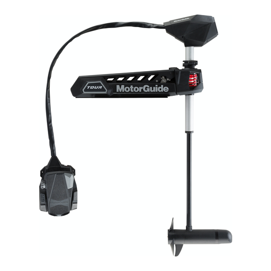
Page 15: Tour Pro 82/Tour Pro 109 Motorguide Trolling Motor
PRODUCT OVERVIEW Tour Pro 82/Tour Pro 109 MotorGuide Trolling Motor 70275 Top housing Depth collar handle Integrated bounce buster (optional) HD+ universal sonar cable (some models) Stow/deploy handle Speed control knob Foot pedal NMEA 2000 cable Momentary on button Anchor button... -
Page 16: Specifications
PRODUCT OVERVIEW Composite column Specifications Speeds Peak Control/ Integrated Pinpoint Shaft Model Volts Thrust Motor Sonar Length Direction Digital TR Pro 114.3 cm 24 V Variable/ 82 45" (45 in.) Forward Digital TR Pro 114.3 cm 36 V Variable/ 109 45" (45 in.) Forward TR Pro... -
Page 17: Wiring And Battery Information
MotorGuide retailer or from www.motorguide.com. • Do not extend the included 10‑gauge battery cables more than 1.8 m (6 ft) for a total of 3 m (10 ft). If longer battery cables are required, MotorGuide offers accessory 8 mm² (8‑gauge) battery cables. •... -
Page 18: Battery Precautions
Any depth sounders or fish finders must be powered from the engine starting or accessory battery. Recommended MotorGuide Accessory Description 8‑gauge battery cable and terminals with 50‑amp manual reset circuit breaker 50‑amp manual reset circuit breaker 60‑amp manual reset circuit breaker... -
Page 19: Wire Color Code Abbreviations
WIRING AND BATTERY INFORMATION Wire Color Code Abbreviations Wire Color Abbreviations Black Blue Brown Gray Green Orange Pink Purple White Yellow Light Dark Battery Connection WARNING Before working around electrical system components, disconnect the battery cables from the battery to prevent injury or damage to the electrical system due to an accidental short circuit. - Page 20 WIRING AND BATTERY INFORMATION 5. Connect the trolling motor negative (–) lead to the negative (–) terminal on battery A. 6. Starting with the positive (+) lead, reconnect the battery cables to the engine starting or accessory battery. BLACK Battery A Battery B 37824 24-volt battery connection...
- Page 21 WIRING AND BATTERY INFORMATION 6. Connect the trolling motor negative (–) lead to the negative (–) terminal on battery A. 7. Starting with the positive (+) lead, reconnect the battery cables to the engine starting or accessory battery. Battery A Battery B Battery C 37825...
-
Page 22: Installing The Steering System On The Mount
3. Remove the steering assembly from the packaging. 4. Remove the plastic latch spacer from the mount. Latch spacer Mount 70112 5. Remove the Motorguide Tour mount accessory kit from the packaging. 6. Install the Allen screws on the steering system assembly. - Page 23 TROLLING MOTOR INSTALLATION AND OPERATION 7. Push the plastic retaining washers onto the Allen screws. 70056 Steering assembly Plastic retaining washers Allen screws IMPORTANT: Be careful not to pinch the stow/deploy handle and cable between the mounting bracket and the steering system. 8.
-
Page 24: Trolling Motor Installation
TROLLING MOTOR INSTALLATION AND OPERATION 9. Tighten one of the two Allen screws to the specified torque. Then tighten the second Allen screw to the specified torque. When the second Allen screw is tightened, verify that the first Allen screw is still tightened to the specified torque. - Page 25 TROLLING MOTOR INSTALLATION AND OPERATION 2. Install the tie‑down strap through the slots in the mount, hook‑and‑loop side down, with the buckle facing toward the outside of the boat. Tie‑down strap Slots Buckle 70015 IMPORTANT: If planning to install the provided bounce buster ensure that the bounce buster contacts the boat on a desired location prior to drilling holes and mounting the motor.
- Page 26 4" hole uncover the 10.2 cm (4 in.) mounting hole pattern pattern that matches the legacy MotorGuide trolling motor mounts. 70119 7.6 cm (3 in.) pattern 10.2 cm (4 in.) pattern...
-
Page 27: Permanent Foot Pedal Mounting-Optional
TROLLING MOTOR INSTALLATION AND OPERATION IMPORTANT: To prevent galling of the mounting hardware, do not use a drill to tighten the mounting screws. If necessary, shim the rubber washers with 25 mm (1 in.) outside diameter stainless steel washers to create a level mounting surface. The mount bracket must lay flush against the rubber isolators before being bolted to the deck or the mount will bind, making it difficult or impossible to unlatch. -
Page 28: Bounce Buster Installation
TROLLING MOTOR INSTALLATION AND OPERATION 6. Push the pedal into the full heel down position and install the rear screw on the foot pedal. Rear screw Front screws (2) 70278 Bounce Buster Installation 1. Place the trolling motor in the stowed position. 2. - Page 29 TROLLING MOTOR INSTALLATION AND OPERATION 5. Cut the bounce buster to the new measurement on the non‑assembled end of the bounce buster. 70135 Distance between the boat deck and outside surface of the mounting bracket Non‑assembled end Add 6.35 mm (1/4 in.) Bounce buster 6.
-
Page 30: Installing The Gas Spring
TROLLING MOTOR INSTALLATION AND OPERATION NOTE: Install the steering system if removed. Refer to Installing the Steering System on the Mount 10. Stow the trolling motor. 70020 11. Adjust the boot end of the bounce buster by removing the rubber boot, loosen the jam nut by turning the screw counter clockwise to the desired length. -
Page 31: Nmea 2000 Pinpoint Connection
TROLLING MOTOR INSTALLATION AND OPERATION 4. Repeat the previous step for the rod end fitting of the gas spring onto the ball stud located on the base of the mount. Piston end fitting Ball stud Gas spring Rod end fitting Mount 70140 5. -
Page 32: Connecting The Sonar Display To The Trolling Motor
NMEA 2000 T‑connector 70279 3. Attach the T‑connector to an existing NMEA 2000 network backbone. If no existing network exists, purchase MotorGuide NMEA 2000 Starter Kit (Part #8M0107522). 4. Use a termination resistor to cap off the remaining open connector end of the T‑Connector if it is the last T in a NMEA 2000 network. -
Page 33: Reducing Sonar Transducer Interference
TROLLING MOTOR INSTALLATION AND OPERATION The trolling motor is equipped with a MotorGuide HD+ universal sonar plug. Adapters are available to connect other brands of sonar displays to the trolling motor. Match the cable connector to the sonar port on the back of the sonar display. -
Page 34: Cable Routing Clip Installation
TROLLING MOTOR INSTALLATION AND OPERATION 5. Connect the sonar display to a separate accessory battery with only the sonar display connected. This will verify if the interference is coming from the power cables or the transducer cable. a. If the interference stops when the sonar display is connected to a separate accessory battery, inspect the boat wiring. -
Page 35: Stowing The Trolling Motor
TROLLING MOTOR INSTALLATION AND OPERATION IMPORTANT: The clip must be within 2.54 cm (1 in.) of the raised part of the side plate to avoid damage to the clip when stowing and deploying. 6. Insert the clip, open side up, into the overhang on the top of either side of the trolling motor mount. -
Page 36: Deploying The Trolling Motor
TROLLING MOTOR INSTALLATION AND OPERATION 3. Continue to pull the stow/deploy handle to raise the lower unit onto the mount. Stow/deploy handle 70019 4. Once the motor is in the stowed position, the stow latch engages to secure the trolling motor. 70021 Mount Tie‑down strap... - Page 37 TROLLING MOTOR INSTALLATION AND OPERATION CAUTION Moving parts, such as hinges and pivot points, can cause serious injury. Keep away from moving parts when stowing, deploying, or tilting the motor. CAUTION Avoid possible serious injury from the motor dropping suddenly when adjusting the motor depth.
-
Page 38: Adjusting The Trolling Motor Depth
TROLLING MOTOR INSTALLATION AND OPERATION 4. Once the motor is in the deployed position, the deploy latch hooks will engage to secure the trolling motor. 70022 Adjusting the Trolling Motor Depth CAUTION Avoid possible serious injury from dropping the motor when adjusting the motor depth. -
Page 39: Directional Indicator
TROLLING MOTOR INSTALLATION AND OPERATION 4. Rotate the cam lock lever until the depth collar binds tightly on the outer column, then close the cam lock arm. Cam lock lever Outer column 70023 Directional Indicator The indicator provides directional information at a glance. 1. -
Page 40: Pinpoint Gps Overview
TROLLING MOTOR INSTALLATION AND OPERATION 4. To reverse direction, continue to press the toe or heel all the way down to point the lower unit toward the back of the boat to move the boat in reverse. 70024 Directional indicator Right turn ‑... - Page 41 TROLLING MOTOR INSTALLATION AND OPERATION Keep unnecessary wiring and power cables away from the trolling motor. Verify that the trolling motor power cables are bundled together. Do not route the power cables separately, particularly within 91.4 cm (36 in.) of the trolling motor.
- Page 42 TROLLING MOTOR INSTALLATION AND OPERATION 15.2 cm (6 in.) 62195 Objects may cause disturbance to the magnetic field within 91 cm (36 in.) of the trolling motor Objects containing iron (such as anchors) Trolling motor power cables (install no more than 15.2 cm [6 in.] apart) LINKING THE HANDHELD REMOTE TO THE TROLLING MOTOR The first time the trolling motor is powered up, the handheld remote will need to be linked to the trolling motor.
- Page 43 TROLLING MOTOR INSTALLATION AND OPERATION If you are having trouble syncing your remote, start with the motor unplugged and deployed. Hold down the left arrow, right arrow, and propeller buttons at the same time before you plug in the motor. Once the battery light turns green, let go of the buttons and the link process should be complete.
- Page 44 TROLLING MOTOR INSTALLATION AND OPERATION WARNING Rotating propellers can cause serious injury or death. Never start or operate the motor out of water. 2. Use the left turn and right turn buttons to steer the unit so that it is facing straight ahead, parallel with the keel of the boat, with the nose cone of the lower unit facing forward and the propeller facing aft.
- Page 45 TROLLING MOTOR INSTALLATION AND OPERATION IMPORTANT: GPS signal strength may vary, depending on satellite reception. This can affect GPS performance. Manual mode #1 button 53737 a. If performing the compass calibration with the boat in the water: locate a suitable area clear of obstructions to navigation (both above and below the waterline) to perform the compass calibration.
-
Page 46: Operating The Pinpoint Gps System
TROLLING MOTOR INSTALLATION AND OPERATION PINPOINT ALIGNMENT CALIBRATION IMPORTANT: This calibration is required and must be completed. It should be repeated when the trolling motor is moved from one boat to another. This calibration can be done with the boat in or out of the water. Left turn Right turn Manual mode... - Page 47 TROLLING MOTOR INSTALLATION AND OPERATION • Lights and functions: a. The Power indicator LED will illuminate when power is connected to the trolling motor. b. The Propeller LED will flash on and off when the Prop button is pressed or when a GPS function requiring the propeller to be on is activated indicating that the prop is moving.
- Page 48 TROLLING MOTOR INSTALLATION AND OPERATION • The trolling motor will emit a three‑beep tune once it has acquired a fixed GPS position, and the GPS status indicator light will illuminate. NOTE: Areas near the North and South poles, remote Northern areas, bridges, severe weather, mountain ranges, and other large obstructions may affect the GPS signal strength.
- Page 49 TROLLING MOTOR INSTALLATION AND OPERATION • The trolling motor will emit a two‑beep tone when the propeller is started, and the propeller status indicator light on the trolling motor will illuminate. • The trolling motor will emit a two‑beep tone when the propeller is stopped, and the propeller status indicator light will turn off.
- Page 50 TROLLING MOTOR INSTALLATION AND OPERATION WARNING A spinning propeller, a moving boat, or any solid device attached to the boat can cause serious injury or death to swimmers. Stop the trolling motor immediately whenever anyone in the water is near your boat. Anchor mode Manual mode 53018...
- Page 51 TROLLING MOTOR INSTALLATION AND OPERATION CAUTION Avoid injury or property damage due to unintended operation. Certain objects —especially magnetic metal objects, such as anchors—can affect the GPS system if they are within or passing through the magnetic field surrounding the trolling motor. Objects obstructing the GPS signal can also have a negative effect on system operation.
- Page 52 TROLLING MOTOR INSTALLATION AND OPERATION Adjusting the Anchor Position 54151 Left turn—"jog" left Increase speed—"jog" ahead Right turn—"jog" right Decrease speed—"jog" behind Once the trolling motor is in anchor mode, the anchor position can be adjusted by pressing the left turn, right turn, increase speed (+), or decrease speed (–) buttons.
- Page 53 TROLLING MOTOR INSTALLATION AND OPERATION NOTE: Pressing a button multiple times will move the anchor position five feet for each time the button is pressed. Storing or Overwriting an Anchor Position Memory buttons (1–8) 54420 NOTE: An anchor position can be stored or overwritten from any operating mode except route record mode.
- Page 54 TROLLING MOTOR INSTALLATION AND OPERATION WARNING Avoid serious injury from colliding with other boats, running aground, or striking objects in the water. The Pinpoint GPS system cannot detect other boats, shallow water, or objects in the water. Always beware of possible obstructions to navigation when operating in any Pinpoint GPS mode.
- Page 55 Both heading lock modes offer advantages to the angler. You can tailor the bait presentation depending on the species of fish, type of bait, underwater terrain, structures, water depth, or environmental conditions. MotorGuide recommends that you experiment with each heading lock mode in different conditions to learn what works best for you.
- Page 56 TROLLING MOTOR INSTALLATION AND OPERATION OPERATING IN HEADING LOCK—COURSE MODE When heading lock—course mode is selected, the trolling motor will lock in and navigate along the trolling motor's heading, while compensating for current, tide, and wind conditions. While in this mode, the operator can adjust the speed and the heading by using the handheld remote or foot pedal.
- Page 57 TROLLING MOTOR INSTALLATION AND OPERATION Heading Lock—Course Mode Operation IMPORTANT: If the trolling motor loses the GPS signal while in a heading lock mode, the trolling motor will emit an error tone, automatically return to manual mode, and continue running at the selected speed. If Cruise control was operating while in a heading lock mode and the GPS signal is lost, the trolling motor will emit an error tone, automatically return to manual mode, and the trolling motor will stop.
- Page 58 TROLLING MOTOR INSTALLATION AND OPERATION Changing the Heading Lock Mode Heading lock—course mode is the default heading lock mode. To switch to heading lock—compass mode, press and hold the manual mode button, then press the 2, 1, 2 buttons in sequence. To switch back to heading lock—course mode, press and hold the manual mode button, then press the 2, 1, 1 buttons in sequence.
- Page 59 TROLLING MOTOR INSTALLATION AND OPERATION 70337 Heading lock button Heading Lock—Compass Mode Operation IMPORTANT: If the trolling motor loses the GPS signal while in a heading lock mode, the trolling motor will emit an error tone, automatically return to manual mode, and continue running at the selected speed.
- Page 60 TROLLING MOTOR INSTALLATION AND OPERATION To switch back to heading lock—course mode, press and hold the manual mode button, then press the 2, 1, 1 buttons in sequence. Adjusting Motor Speed If a heading lock mode is selected from manual mode, the trolling motor will run at the last selected speed.
- Page 61 TROLLING MOTOR INSTALLATION AND OPERATION WARNING Avoid serious injury from colliding with other boats, running aground, or striking objects in the water. The Pinpoint GPS system cannot detect other boats, shallow water, or objects in the water. Always beware of possible obstructions to navigation when operating in any Pinpoint GPS mode.
- Page 62 TROLLING MOTOR INSTALLATION AND OPERATION Recalling a Stored Route A stored route can be recalled while operating in any mode by pressing the route playback button, then pressing the desired memory button. The trolling motor will emit an ascending chirp to indicate that the route has been successfully recalled.
- Page 63 TROLLING MOTOR INSTALLATION AND OPERATION If the selected memory position is empty, or if the boat is over 1.6 km (1 mile) from a point on the selected route, the trolling motor will emit an error tone and exit the route mode. IMPORTANT: If the trolling motor loses the GPS signal while in any GPS mode, the trolling motor will emit an error tone and automatically return to manual mode.
- Page 64 TROLLING MOTOR INSTALLATION AND OPERATION WARNING Avoid serious injury from colliding with other boats, running aground, or striking objects in the water. The Pinpoint GPS system cannot detect other boats, shallow water, or objects in the water. Always beware of possible obstructions to navigation when operating in any Pinpoint GPS mode.
- Page 65 TROLLING MOTOR INSTALLATION AND OPERATION IMPORTANT: If the trolling motor loses the GPS signal while in any GPS mode, the trolling motor will emit an error tone and automatically return to manual mode. IMPORTANT: Cruise control function can be affected by the quality of the GPS signal.
- Page 66 TROLLING MOTOR INSTALLATION AND OPERATION Audio Audio Mode 1 Audio Audio Condition Pattern (Default) Mode 2 Mode 3 Speed + (when less Short beep – – than maximum speed) Speed + (at maximum 2 beeps – speed) Speed – (when greater Short beep –...
-
Page 67: Speed Control
TROLLING MOTOR INSTALLATION AND OPERATION Speed Control All Tour Pro motors are equipped with digital variable speed control. Control the speed of your motor by rolling the speed control knob with your hand or foot until you reach the desired speed. 70342 Momentary switch Foot pedal... - Page 68 TROLLING MOTOR INSTALLATION AND OPERATION • 5: 2, 3, 5 ‑ Most resistance, heavier feel.
-
Page 69: Maintenance
Do not perform maintenance or service on your trolling motor if you are not familiar with the correct service and safety procedures. SELECTING REPLACEMENT PARTS We recommend using original MotorGuide Certified replacement parts. Inspection and Maintenance Schedule BEFORE EACH USE •... -
Page 70: Lubrication Points
15 minutes before going above 30% operation. Lubrication Points NOTE: Preferred lubricants can be obtained at any authorized MotorGuide or Mercury Marine service center. To reduce friction and quiet squeaks, lubricate the specified locations periodically with the following lubricants: •... -
Page 71: Propeller Replacement
MAINTENANCE Propeller Replacement WARNING Performing service or maintenance without first disconnecting the battery can cause product damage, personal injury, or death due to fire, explosion, electrical shock, or unexpected motor starting. Always disconnect the battery cables from the battery before maintaining, servicing, installing, or removing motor components. -
Page 72: Adjusting The Steering Cable Tension
MAINTENANCE 2. Install the propeller onto the motor shaft by engaging the propeller onto the propeller pin. 3. Install the washer onto the propeller shaft, then install the propeller nut. Use a wrench or a socket and ratchet to tighten the propeller nut until it is snug, then tighten the nut another 1/4 turn. -
Page 73: Troubleshooting
TROUBLESHOOTING Trolling Motor Performance Symptom Possible Cause Resolution Weak battery Refer to Wiring and Battery Loose or corroded battery Information. connections Propeller is loose, Refer to Maintenance. damaged, or off‑balance Wire gauge from the battery Loss of power Wiring or electrical to the trolling motor is connection faulty insufficient. -
Page 74: Reducing Sonar Transducer Interference
TROUBLESHOOTING Symptom Possible Cause Resolution Lubricate the lock pins on the Mount bracket Lock pins need lubrication mount bracket with 2‑4‑C squeaks with PTFE. Loosen the cable tension The cable tension screw screw and tighten only until Excessive steering is too tight. there is no play in the foot pedal pad. - Page 75 TROUBLESHOOTING 7. Connect the sonar display to a different transducer.
-
Page 76: Owner Service Assistance
OWNER SERVICE ASSISTANCE Mercury Marine Service Offices For assistance, call, fax, or write. Please include your daytime telephone number with mail and fax correspondence. United States, Canada English +1 920 929 5040 Mercury Marine Telephone Français + 905 636 4751 W6250 Pioneer Road P.O.
Need help?
Do you have a question about the Tour Pro 82 and is the answer not in the manual?
Questions and answers