Table of Contents
Advertisement
Advertisement
Table of Contents

Related Manuals for MotorGuide Wireless


Summary of Contents for MotorGuide Wireless
- Page 1 90-MM5981...
- Page 2 This device may not cause harmful interference, This device must accept any interference received, including interference that may cause undesired operation. This device complies with FCC Rules. Changes or modifications not expressly approved by MotorGuide could void the user's authority to operate the equipment.
- Page 3 Congratulations … on your purchase of the MotorGuide Wireless Trolling Motor. This motor has been designed, engineered, and manufactured to give you the best possible dependability and exceptional performance for years of enjoyment. These features offer an unrivaled fishing experience:...
-
Page 4: Table Of Contents
Safety DO’s and DON’Ts ..............3 Operating Safety ................4 NOTES: ....................5 Features & Components FEATURES.....................6 Remote Capabilities ................6 COMPONENTS ..................7 Wireless Remote Foot-Pedal .............7 Lower Unit ..................7 Column ....................7 Top Housing ..................7 Cradle Lock™ Mount .................8 Battery Indicator .................8 Installation INSTALLATION ..................10 Mount Installation ................10... - Page 5 MAINTENANCE ...................21 Foot-Pedal Battery Replacement .............21 Care & Cleaning Instructions ............22 Customer Responsibilities..............22 Battery..................22 Freezing Temperature Storage............23 Installing or Replacing the Propeller ..........23 Troubleshooting & Accessories TROUBLESHOOTING .................25 Frequently Asked Questions ............25 MOTORGUIDE ACCESSORIES 28 Warranty MOTORGUIDE LIMITED THREE-YEAR WARRANTY .......29...
- Page 6 MOTORGUIDE WIRELESS NOTES: ____________________________________________________ ____________________________________________________ ____________________________________________________ ____________________________________________________ ____________________________________________________ ____________________________________________________ ____________________________________________________ ____________________________________________________ ____________________________________________________ ____________________________________________________ ____________________________________________________ ____________________________________________________ ____________________________________________________ ____________________________________________________ ____________________________________________________ ____________________________________________________ 8M4000137 For Questions, Contact Consumer Affairs at #1-920-929-5040 © 2005, MotorGuide www.motorguide.com...
-
Page 7: General Information
The description and specifications contained herein were in effect at the time this manual was approved for printing. MotorGuide, whose policy is one of continual improvement, reserves the right to discontinue models at any time, to change specifications, designs, and methods of procedure without notice and without incurring obligation. -
Page 8: Safety Do's And Don'ts
MOTORGUIDE WIRELESS CAUTION Disconnect the trolling motor from the battery(s) before charging. How to Use This Manual Review the following information carefully. These notices will alert you to potential dangers and important information. The observance of WARNINGS and CAUTIONS alone does not eliminate the possibility of personal injury or product damage. -
Page 9: Operating Safety
MOTORGUIDE WIRELESS Circuit Protection – MotorGuide recommends installing a 50 amp manual-reset circuit breaker and power switch in line with the trolling motor positive leads within (1.8 m) 72 inches of the battery(s). To order a circuit breaker kit, contact your local Service Dealer, request kit number MM5870. -
Page 10: Notes
The use of a sacrificial anode causes all of the other metals on the tolling motor to become the cathodes. The anode will corrode and the trolling motor will not. Maintenance: If excessive corrosion occurs, replace the anode. To order a Wireless Sacrificial Anode Kit contact your local Service Dealer, request kit number MM5870. NOTES:... -
Page 11: Features
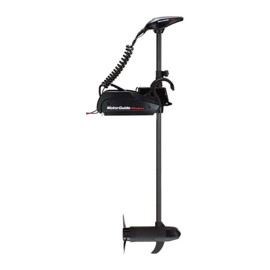
Top Housing Wireless Foot-Pedal Remote Capabilities The MotorGuide Wireless uses a remote foot-pedal with the receiver built into the trolling motor mount. These remote capabilities work with the Digital Remote Control (DRC) product and up to four remotes (including the foot- pedal) can be used with one motor. -
Page 12: Components
The oversized brushes increase battery life and extend trolling time. Column he MotorGuide Wireless composite shaft is exceptionally strong, and flexible. The shaft comes in 48, 54 and 60 inch lengths. Top Housing The sleek top housing design indicates, at-a-glance, the direction of the motor. -
Page 13: Cradle Lock™ Mount
MOTORGUIDE WIRELESS Prop The MotorGuide Wireless uses the 3½ inch two blade Power Prop. Cradle Lock™ Mount The rock solid design of the MotorGuide Wireless mount has a quick-release mounting plate and an easy access lever for trouble-free stowing and deploying the motor. - Page 14 MOTORGUIDE WIRELESS NOTES: ____________________________________________________ ____________________________________________________ ____________________________________________________ ____________________________________________________ ____________________________________________________ ____________________________________________________ ____________________________________________________ ____________________________________________________ ____________________________________________________ ____________________________________________________ ____________________________________________________ ____________________________________________________ ____________________________________________________ ____________________________________________________ ____________________________________________________ ____________________________________________________ 8M4000137 For Questions, Contact Consumer Affairs at #1-920-929-5040 © 2005, MotorGuide www.motorguide.com...
-
Page 15: Installation
MOTORGUIDE WIRELESS INSTALLATION Mount Installation It is recommended that two people install the motor and mount. ! WARNING Do not connect the motor to a power source until the motor and mount are fully installed on the boat. The tools required for the installation are:... - Page 16 MOTORGUIDE WIRELESS Place the mount base plate on the boat deck aligning the holes on the plate to the holes on the deck. Install the four (4) stainless steel mounting bolts through each of the mounting holes. Install the four (4) stainless steel washers and nuts on the bottom side of the deck and tighten securely.
- Page 17 MOTORGUIDE WIRELESS 10) Sit the back of the mount housing over the back of the mount base. Press down on the back of the mount base and turn the mount locking knob just enough to engage the cam locking mechanism and secure the mount onto the base plate.
-
Page 18: Wiring & Battery Information
For storage and security purposes the MotorGuide Wireless Cradle Lock™ mount makes it easy to completely remove and reinstall the mount and motor. When the mount and motor are removed from the boat, a snap-on Wireless Mounting Plate Cover (see the Accessories section of this manual for order information) is available to protect the mounting plate. -
Page 19: Establishing A Common Ground
(6) gauge (13 mm) wires if extending the existing wire beyond the standard battery cable supplied with the product. Bow Plugs – MotorGuide recommends the use of a quality plug designed 8M4000137 For Questions, Contact Consumer Affairs at #1-920-929-5040 ©... - Page 20 MOTORGUIDE WIRELESS for marine applications. 12 Volt Battery Hook-up A) Black battery lead (-) D) Jumper Wire B) Red battery lead (+) C) 50 amp circuit E) To trolling r Breaker and a power motor connections switch Connect the red battery lead from the power cable to the battery positive (+) post and the black battery lead from the power cable to the battery negative (-) post.
- Page 21 MOTORGUIDE WIRELESS 24 Volt Battery Hook-up A) Battery A E) Red battery leads (+) B) Battery B F) 50 amp circuit breaker and a power C) To trolling motor connections switch D) Black battery leads (-) G) Jumper wires Connect the black battery lead from the power cable to the negative (-) post on battery A and the red lead from the power cable o the positive (+) post on battery B.
-
Page 22: Activating The Foot-Pedal Electronic Id
MOTORGUIDE WIRELESS Activating the Foot-Pedal Electronic ID Each foot-pedal has a unique electronic ID number. Up to four electronic ID numbers (Digital Remote Control units and/or foot-pedals) can be stored by your receiver. For your foot-pedal to respond to your commands only and not those of other boaters, you must activate the electronic ID number into your receiver. -
Page 23: Motor & Mount Operation
MOTORGUIDE WIRELESS MOTOR & MOUNT OPERATION Adjusting the Motor Depth and Deploying the Motor Loosen the depth collar by turning the knob handle. Slide the depth collar up or down the shaft to a position that will allow the lower unit to be submerged at least 12 inches (30cm) below the water surface when the motor is fully deployed. -
Page 24: Stowing The Motor
MOTORGUIDE WIRELESS Stowing the Motor Pull up the release handle and then, holding the shaft or top housing, lift the motor up. Release Handle While lifting the motor out of the water, rotate the shaft until the lower unit is aligned with the locking cradle. -
Page 25: Operating The Foot-Pedal
MOTORGUIDE WIRELESS Operating the Foot-Pedal INFORMATION Ensure the foot-pedal electronic ID has been activated. See the “Installation” section of this manual for instructions. On/Off Button Slower Button Faster Button Prop On/Off Turn the prop on or off by pressing the center button and it will alternate between on and off. -
Page 26: Maintenance
MOTORGUIDE WIRELESS MAINTENANCE Foot-Pedal Battery Replacement Use only a 3V lithium type CR2032 replacement battery. These batteries are not rechargeable. Follow these instructions to change the battery: Remove the five screws on the battery cover plate located on the underside of the foot-pedal. -
Page 27: Care & Cleaning Instructions
MOTORGUIDE WIRELESS Care & Cleaning Instructions To keep your trolling motor looking its best: Periodically wash it with warm soapy water and a soft cloth or sponge. Do not use a high pressure or power washer. Use a vinyl/rubber UV protector, available in any auto store, to keep the cables looking fresh. -
Page 28: Freezing Temperature Storage
Do not strike a bent prop pin with a hammer to remove the pin. This may cause damage to the armature, which is not covered by warranty. MotorGuide recommends using pliers. When handling the prop, first check for sharp edges or wear protective gloves to prevent cuts to the hands. - Page 29 If the propeller pin is bent, replace it. Align the new propeller with the propeller pin. Reinstall the propeller nut and tighten securely with your fingers. Tighten another 1/4 turn using a MotorGuide Prop Wrench, part number MGA050B6. 8M4000137 For Questions, Contact Consumer Affairs at #1-920-929-5040 ©...
-
Page 30: Troubleshooting
MOTORGUIDE WIRELESS TROUBLESHOOTING Frequently Asked Questions The receiver beeps when I press a button on the foot-pedal but nothing happens. The receiver does not have the foot-pedals electronic ID number programmed; refer to the “Activating the Electronic ID number” section of this manual. - Page 31 MOTORGUIDE WIRELESS exist in the boat wiring or trolling motor wiring. • The permanent magnets may be cracked or chipped. The motor will whine or grind. • There may be water in the lower unit. • The propeller may be fouled. Remove the...
- Page 32 Refer to your nearest Service Dealer for assistance with trolling motor repairs. FOR REPAIR SERVICE Contact your nearest MotorGuide Service Dealer. See a complete listing of Service Dealers in the US and Canada at our MotorGuide web site: www.motorguide.com. Call Mercury Marine Consumer Affairs to obtain the name and location of the Service Dealer nearest you.
-
Page 33: Motorguide Accessories
MOTORGUIDE WIRELESS MOTORGUIDE ACCESSORIES Making It More Perfect. Who says you cannot make the best even better? MotorGuide® factory accessories let fishermen customize motors to their own unique needs. In addition, every one is a perfect fit. REPLACEMENT PROPS Prop Description Number 3.5"... -
Page 34: Motorguide Limited Three-Year Warranty
(3). MotorGuide will provide a new Wireless composite shaft at no cost for any Wireless composite shaft which contains a defect in material or workmanship. The installation costs are the sole responsibility of the purchaser. - Page 35 MOTORGUIDE WIRELESS IMPORTANT!! REGISTER YOUR PRODUCT The warranty registration card (located in the box) should be completed and mailed to Mercury Marine to validate your warranty. To replace a lost warranty card, contact the Mercury Marine Registration Department at 1-920-929-5054.
- Page 36 MotorGuide 835 W. 41 Street Tulsa, Oklahoma 74107 (920) 929-5040...
Need help?
Do you have a question about the Wireless and is the answer not in the manual?
Questions and answers
I have a Model 940200090 S/N 9D533640. I would like to convert it to a wireless remote, if possible. If so, what parts will I need. Also is there a link to show me how.