Table of Contents
Advertisement
Advertisement
Table of Contents

Subscribe to Our Youtube Channel
Related Manuals for MotorGuide X3-40


Summary of Contents for MotorGuide X3-40
- Page 1 Operation Maintenance Installation Warranty Manual...
- Page 3 EU Compliance Statement Attwood Corporation hereby declares that the MotorGuide X3 trolling motor is in compliance with the essential requirements and other relevant provisions of the 99/5/EC R&TTE directive. CE Declaration Manufacturer: Attwood Corporation Address: 1016 N. Monroe Lowell, MI 49331 USA Telephone: 616‑897‑9241...
- Page 4 Warranty Message The product you have purchased comes with a Two Year Limited Warranty from MotorGuide, the terms of the policy are set forth in the Warranty Information section of this manual. The policy statement contains a description of the duration of coverage, important disclaimers and limitations of damages, and other related information.
-
Page 5: Table Of Contents
Warranty Information MotorGuide Limited Two Year Warranty............1 General Information Boater's Responsibilities..................3 Protecting People in the Water................3 Passenger Safety Message................3 Safe Boating Suggestions.................. 3 Product Overview X3‑40/X3‑45/X3‑55/X3‑70 MotorGuide Trolling Motor........5 Specifications...................... 6 Wiring and Battery Information Wiring and Battery Information................ - Page 6 Trolling Motor Care................... 26 Inspection and Maintenance Schedule............. 26 Lubrication Points..................... 27 Battery Inspection..................... 27 Propeller Replacement..................28 Adjusting the Steering Cable Tension.............. 30 MotorGuide Accessories Inquiries..............31 Troubleshooting Trolling Motor Performance................32 Owner Service Assistance Mercury Marine Service Offices................ 34...
-
Page 7: Warranty Information
(2) years. Warranty is NOT transferable to any subsequent purchaser. 3. MotorGuide, at its discretion, will repair or replace items covered under the terms of this warranty. Neither MotorGuide nor MotorGuide service... - Page 8 3) use of an accessory or part not manufactured by MotorGuide/ Mercury; 4) alteration or removal of parts; 5) opening the lower unit (motor) by anyone other than the Factory Service Center will void this warranty.
-
Page 9: General Information
GENERAL INFORMATION Boater's Responsibilities The operator (driver) is responsible for the correct and safe operation of the boat and safety of its occupants and general public. It is strongly recommended that each operator (driver) read and understand this entire manual before operating the trolling motor. - Page 10 GENERAL INFORMATION Do not overload your boat. Most boats are rated and certified for maximum load (weight) capacities, refer to your boat capacity plate. If in doubt, contact your dealer or the boat's manufacturer. Perform safety checks and required maintenance. Follow a regular schedule and ensure all repairs are made properly.
-
Page 11: Product Overview
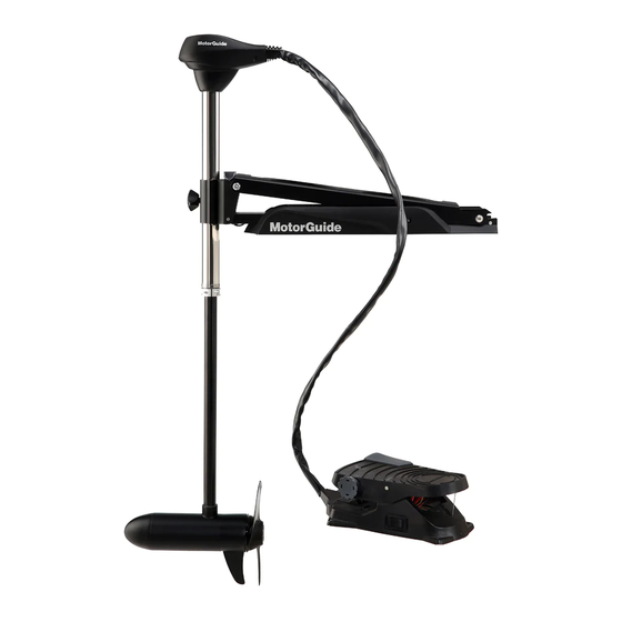
PRODUCT OVERVIEW X3‑40/X3‑45/X3‑55/X3‑70 MotorGuide Trolling Motor CABLE STEER MODELS Directional indicator Mount bracket Battery cables Latch release handle Speed control Three‑position switch Foot pedal Serial number decal (under the foot pedal) Momentary switch Propeller Lower unit Composite column Bracket door knob... -
Page 12: Specifications
PRODUCT OVERVIEW HAND-OPERATED MODELS 54512 Top housing Extendable speed control tiller handle Serial number decal Battery cables Latch release handle Mount bracket Composite column Propeller Lower unit Bracket door knob Steering tension collar Depth adjustment collar Specifications Speeds Freshwater/ Peak Shaft Model Control... - Page 13 PRODUCT OVERVIEW Speeds Freshwater/ Peak Shaft Model Control Volts Forward/ Saltwater Thrust Length Reverse Extendable X3‑55 24.9 kgf 127.0 cm hand/ Freshwater 12 V (55 lbf) (50 in.) twist‑tiller Extendable X3‑70 31.8 kgf 127.0 cm hand/ Freshwater 24 V (70 lbf) (50 in.) twist‑tiller X3‑55...
- Page 14 PRODUCT OVERVIEW Speeds Freshwater/ Peak Shaft Model Control Volts Forward/ Saltwater Thrust Length Reverse X3‑55 Foot pedal/ 24.9 kgf 91.4 cm Freshwater 12 V Variable cable steer (55 lbf) (36 in.) Digital X3‑55 Foot pedal/ 24.9 kgf 106.7 cm Freshwater 12 V cable steer (55 lbf)
-
Page 15: Wiring And Battery Information
MotorGuide retailer or from www.motorguide.com. • Do not extend the included 10‑gauge battery cables more than 1.8 m (6 ft) for a total of 3 m (10 ft). If longer battery cables are required, MotorGuide offers accessory 8 mm² (8‑gauge) battery cables. •... -
Page 16: Battery Precautions
WIRING AND BATTERY INFORMATION Recommended MotorGuide Accessory Description 60‑amp manual reset circuit breaker Battery Precautions WARNING An operating or charging battery produces gas that can ignite and explode, spraying out sulfuric acid, which can cause severe burns. Ventilate the area around the battery and wear protective equipment when handling or servicing batteries. -
Page 17: Battery Connection
WIRING AND BATTERY INFORMATION Battery Connection WARNING Before working around electrical system components, disconnect the battery cables from the battery to prevent injury or damage to the electrical system due to an accidental short circuit. CAUTION Disconnecting or connecting the battery cables in the incorrect order can cause injury from electrical shock or can damage the electrical system. - Page 18 WIRING AND BATTERY INFORMATION 6. Starting with the positive (+) lead, reconnect the battery cables to the engine starting or accessory battery. 45086 Power cables to trolling motor Manual reset circuit breaker Trolling motor battery Engine starting or accessory battery Power cables to engine Common ground bond 24-VOLT BATTERY CONNECTION...
- Page 19 WIRING AND BATTERY INFORMATION 6. Starting with the positive (+) lead, reconnect the battery cables to the engine starting or accessory battery. BLACK Battery A Battery B 37824 Power cables to trolling motor Manual reset circuit breaker Jumper wire (not supplied) Negative (–) battery terminal...
-
Page 20: Trolling Motor Installation And Operation
TROLLING MOTOR INSTALLATION AND OPERATION Mount Bracket Installation 54513 X3 bow mount bracket Latch release handle Bracket door knob 1. Select an appropriate area on the deck of the boat to install the mount. Ensure that the forward mounting screws will not penetrate the hull. IMPORTANT: Choose an area on the boat deck that allows a 7.6 cm (3 in.) clearance between the bow of the boat and the column of the trolling motor. - Page 21 TROLLING MOTOR INSTALLATION AND OPERATION IMPORTANT: A minimum of four mounting bolts are required to mount the trolling motor to the boat. Spread the mounting bolts as far apart as practical for the most secure mounting. Mount bracket mounting holes a a a 54516 3.
-
Page 22: Permanent Foot Pedal Mounting (Optional)
TROLLING MOTOR INSTALLATION AND OPERATION IMPORTANT: If necessary, shim the rubber washers with 25 mm (1 in.) outside diameter stainless steel washers to create a level mounting surface. Mount bracket Mounting bolt Rubber isolator Deck Washer Nylon locking nut 56543 6. -
Page 23: Installing The Motor Into The Bow Mount
TROLLING MOTOR INSTALLATION AND OPERATION 4. Use four #8 x 2 in. stainless steel screws to secure the foot pedal to the boat deck. 54589 Installing the Motor into the Bow Mount Steering tension collar (hand‑operated models only) Bracket door Bracket door knob 54517 1. -
Page 24: Stowing The Trolling Motor
TROLLING MOTOR INSTALLATION AND OPERATION Stowing the Trolling Motor WARNING Rotating propellers can cause serious injury or death. Never start or operate the motor out of water. CAUTION Moving parts, such as hinges and pivot points, can cause serious injury. Keep away from moving parts when stowing, deploying, or tilting the motor. -
Page 25: Deploying The Trolling Motor
TROLLING MOTOR INSTALLATION AND OPERATION 4. Once the motor is in the stowed position, the lock pin engages to secure the trolling motor. 54520 X3 in the stowed position 5. Position the tie‑down strap over the composite column and through the buckle. -
Page 26: Adjusting The Steering Tension (Hand-Operated Motors Only)
TROLLING MOTOR INSTALLATION AND OPERATION 3. Snap the latch release handle to disengage the lock pin. 4. Continue to maintain tension on the latch release handle while lowering the trolling motor into the water. IMPORTANT: Gently lower the trolling motor into the water. Do not release the latch release handle until the lock pin is engaged. -
Page 27: Adjusting The Motor Depth
TROLLING MOTOR INSTALLATION AND OPERATION 2. To reduce the steering tension, turn the steering tension collar counterclockwise. Steering tension collar 54522 Adjusting the Motor Depth CAUTION Avoid possible serious injury from dropping the motor when adjusting the motor depth. Firmly grasp the motor shaft with one hand when raising or lowering the motor. - Page 28 TROLLING MOTOR INSTALLATION AND OPERATION CABLE STEER MODELS IMPORTANT: When adjusting the motor depth, ensure that the propeller blades are fully submerged 15–30 cm (6–12 in.) below the water surface to avoid ventilation. 1. Firmly grasp the column with one hand. 2.
-
Page 29: Directional Indicator-Cable Steer Models
TROLLING MOTOR INSTALLATION AND OPERATION Directional Indicator—Cable Steer Models The indicator provides directional information at a glance. 54533 Directional indicator Right turn ‑ toe down; motor steers boat to right (continue to press all the way down for reverse) Straight ahead ‑ foot pedal in middle Left turn ‑... -
Page 30: Speed Control-Cable Steer Models
TROLLING MOTOR INSTALLATION AND OPERATION Speed Control—Cable Steer Models FIVE-SPEED AND DIGITAL VARIABLE SPEED MOTORS Foot operated motors are available as five‑speed models or with digital variable speed control. Control the speed of your motor by rolling the speed control knob with your hand or foot until you reach the desired speed. -
Page 31: Speed Control-Hand-Operated Models
TROLLING MOTOR INSTALLATION AND OPERATION Speed Control—Hand‑Operated Models Adjust the speed control to the desired direction and thrust level. Rotate the twist‑tiller handle clockwise for forward movement or counterclockwise for reverse movement. The "off" handle position stops the motor. Five‑speed models have five forward speed settings and two reverse speed settings. -
Page 32: Maintenance
Do not perform maintenance or service on your trolling motor if you are not familiar with the correct service and safety procedures. SELECTING REPLACEMENT PARTS We recommend using original MotorGuide Certified Tough replacement parts. Inspection and Maintenance Schedule BEFORE EACH USE •... -
Page 33: Lubrication Points
15 minutes before going above 30% operation. Lubrication Points NOTE: Preferred lubricants can be obtained at any authorized MotorGuide or Mercury Marine service center. To reduce friction and quiet squeaks, lubricate the specified locations periodically with the following lubricants: •... -
Page 34: Propeller Replacement
MAINTENANCE IMPORTANT: Read the safety and maintenance instructions which accompany your battery. 1. Ensure that the battery is secured to the vessel. 2. Ensure that the battery cable terminals are clean, tight, and correctly installed. For installation instructions, refer to Battery Connection. 3. - Page 35 MAINTENANCE NOTE: If the propeller pin is bent, replace the propeller pin. 53442 44663 INSTALLING THE PROPELLER 1. Rotate the motor shaft to insert the propeller pin horizontally. Propeller pin 44664 2. Install the propeller onto the motor shaft by engaging the propeller onto the propeller pin.
-
Page 36: Adjusting The Steering Cable Tension
MAINTENANCE 3. Install the washer (or anode, for saltwater models) onto the propeller shaft then install the propeller nut. Tighten the propeller nut securely. 53442 4. Tighten the propeller nut another ¼ turn. Adjusting the Steering Cable Tension WARNING Neglecting to inspect, maintain, or repair your trolling motor can result in product damage or serious injury or death. -
Page 37: Motorguide Accessories Inquiries
MAINTENANCE Description lb‑in. lb‑ft Cable tension screw – Bottom of foot pedal Cable tension screw 54574 MotorGuide Accessories Inquiries Refer to www.motorguide.com for factory authorized accessories for all MotorGuide trolling motors. -
Page 38: Troubleshooting
TROUBLESHOOTING Trolling Motor Performance Symptom Possible Cause Resolution Weak battery Refer to Wiring and Battery Loose or corroded battery Information. connections Propeller is loose, Refer to Maintenance. damaged, or off‑balance Wire gauge from the battery Loss of power Wiring or electrical to the trolling motor is connection faulty insufficient. - Page 39 TROUBLESHOOTING Symptom Possible Cause Resolution Lubricate the lock pins on the Mount bracket Lock pins need lubrication mount bracket with 2‑4‑C squeaks with PTFE.
-
Page 40: Owner Service Assistance
OWNER SERVICE ASSISTANCE Mercury Marine Service Offices For assistance, call, fax, or write. Please include your daytime telephone number with mail and fax correspondence. United States, Canada English +1 920 929 5040 Mercury Marine Telephone Français + 905 636 4751 W6250 Pioneer Road P.O.
Need help?
Do you have a question about the X3-40 and is the answer not in the manual?
Questions and answers