Table of Contents
Advertisement
Advertisement
Table of Contents

Related Manuals for MotorGuide X5 Series


Summary of Contents for MotorGuide X5 Series
- Page 1 Operation Maintenance Installation Warranty Manual...
- Page 3 EU Compliance Statement Attwood Corporation hereby declares that the MotorGuide X5 trolling motor is in compliance with the essential requirements and other relevant provisions of the 99/5/EC R&TTE directive. CE Declaration Manufacturer: Attwood Corporation Address: 1016 N. Monroe Lowell, MI 49331 USA Telephone: 616‑897‑9241...
- Page 4 Warranty Message The product you have purchased comes with a Two Year Limited Warranty from MotorGuide, the terms of the policy are set forth in the Warranty Information section of this manual. The policy statement contains a description of the duration of coverage, important disclaimers and limitations of damages, and other related information.
-
Page 5: Table Of Contents
Warranty Information MotorGuide Limited Two Year Warranty............1 General Information Boater's Responsibilities..................3 Protecting People in the Water................3 Passenger Safety Message................3 Safe Boating Suggestions.................. 3 Product Overview X5‑55/X5‑70/X5‑80/X5‑105 MotorGuide Trolling Motor........5 Specifications...................... 7 Wiring and Battery Information Wiring and Battery Information................ - Page 6 Battery Inspection..................... 30 Corrosion Control Anode (Saltwater Models)........... 31 Propeller Replacement..................31 Adjusting the Steering Cable Tension.............. 33 Front Locking Pin Replacement................ 34 MotorGuide Accessories Inquiries..............35 Troubleshooting Trolling Motor Performance................36 Reducing Sonar Transducer Interference............37 Owner Service Assistance...
-
Page 7: Warranty Information
Warranty coverage and duration varies by the country in which the product resides. This warranty applies to X5 series MotorGuide trolling motors sold and residing in the United States. This Limited Warranty begins on the date the product is first sold to a purchaser or the date on which the product is first put into service, whichever occurs first. - Page 8 3) use of an accessory or part not manufactured by MotorGuide/ Mercury; 4) alteration or removal of parts; 5) opening the lower unit (motor) by anyone other than the Factory Service Center will void this warranty.
-
Page 9: General Information
GENERAL INFORMATION Boater's Responsibilities The operator (driver) is responsible for the correct and safe operation of the boat and safety of its occupants and general public. It is strongly recommended that each operator (driver) read and understand this entire manual before operating the trolling motor. - Page 10 GENERAL INFORMATION Do not overload your boat. Most boats are rated and certified for maximum load (weight) capacities, refer to your boat capacity plate. If in doubt, contact your dealer or the boat's manufacturer. Perform safety checks and required maintenance. Follow a regular schedule and ensure all repairs are made properly.
-
Page 11: Product Overview
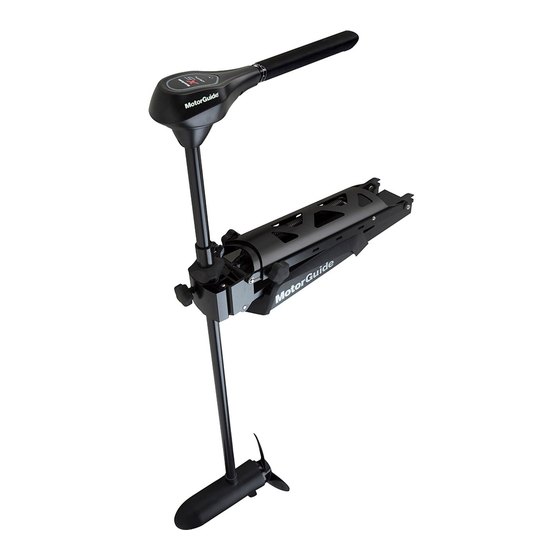
PRODUCT OVERVIEW X5‑55/X5‑70/X5‑80/X5‑105 MotorGuide Trolling Motor CABLE STEER MODELS 58588 Top housing 53.3 cm (21 in.) mount bracket Latch release handle Foot pedal Momentary on button 3‑position switch Speed control knob Battery cables 61 cm (24 in.) mount bracket (optional) - Page 12 PRODUCT OVERVIEW HAND-OPERATED MODELS 62253 Top housing Extendable speed control tiller handle Serial number decal Battery cables Latch release handle 53.3 cm (21 in.) mount bracket Composite column Propeller Lower unit Bracket door knob Steering tension collar Depth adjustment collar...
-
Page 13: Specifications
PRODUCT OVERVIEW Specifications NOTE: Freshwater models are abbreviated as FW . Saltwater models are abbreviated as SW . Speeds Peak Shaft Model Control Type Volts Forward/ Sonar Thrust Length Reverse X5‑55 Foot pedal/ 24.9 kgf 114.3 cm 12 V Variable cable steer (55 lbf) (45 in.) - Page 14 PRODUCT OVERVIEW Speeds Peak Shaft Model Control Type Volts Forward/ Sonar Thrust Length Reverse X5‑105 Foot pedal/ 47.6 kgf 127.0 cm 36 V Variable cable steer (105 lbf) (50 in.) X5‑105 Foot pedal/ 47.6 kgf 127.0 cm 36 V Variable cable steer (105 lbf) (50 in.)
-
Page 15: Wiring And Battery Information
MotorGuide retailer or from www.motorguide.com. • Do not extend the included 10‑gauge battery cables more than 1.8 m (6 ft) for a total of 3 m (10 ft). If longer battery cables are required, MotorGuide offers accessory 8 mm² (8‑gauge) battery cables. •... -
Page 16: Battery Precautions
Any depth sounders or fish finders must be powered from the engine starting or accessory battery. Recommended MotorGuide Accessory Description 8‑gauge battery cable and terminals with 50‑amp manual reset circuit breaker 50‑amp manual reset circuit breaker 60‑amp manual reset circuit breaker... -
Page 17: Wire Color Code Abbreviations
WIRING AND BATTERY INFORMATION Wire Color Code Abbreviations Wire Color Abbreviations Black Blue Brown GRY or GRA Gray Green ORN or ORG Orange Pink PPL or PUR Purple White Yellow LT or LIT Light DK or DRK Dark Battery Connection WARNING Before working around electrical system components, disconnect the battery cables from the battery to prevent injury or damage to the electrical system... - Page 18 WIRING AND BATTERY INFORMATION 6. Starting with the positive (+) lead, reconnect the battery cables to the engine starting or accessory battery. 45086 Power cables to trolling motor Manual reset circuit breaker Trolling motor battery Engine starting or accessory battery Power cables to engine Common ground bond 24-VOLT BATTERY CONNECTION...
- Page 19 WIRING AND BATTERY INFORMATION 6. Starting with the positive (+) lead, reconnect the battery cables to the engine starting or accessory battery. BLACK Battery A Battery B 37824 24-volt battery connection Power cables to trolling motor Manual reset circuit breaker Jumper wire (not supplied) Negative (–) battery terminal 36-VOLT BATTERY CONNECTION...
- Page 20 WIRING AND BATTERY INFORMATION 7. Starting with the positive (+) lead, reconnect the battery cables to the engine starting or accessory battery. Battery A Battery B Battery C 37825 36-volt battery connection Power cables to trolling motor Manual reset circuit breaker Jumper wire (not supplied) Negative (–) battery terminal...
-
Page 21: Trolling Motor Installation And Operation
TROLLING MOTOR INSTALLATION AND OPERATION Mount Bracket Installation 58592 X5 bow mount bracket Latch release handle Bracket door knob 1. Select an appropriate area on the deck of the boat to install the mount. Ensure that the forward mounting screws will not penetrate the hull. IMPORTANT: Choose an area on the boat deck that allows a 7.6 cm (3 in.) clearance between the bow of the boat and the column of the trolling motor. - Page 22 TROLLING MOTOR INSTALLATION AND OPERATION IMPORTANT: A minimum of four mounting bolts are required to mount the trolling motor to the boat. Spread the mounting bolts as far apart as practical for the most secure mounting. 58594 Mount bracket mounting holes (5 per side) 3.
-
Page 23: Permanent Foot Pedal Mounting (Optional)
TROLLING MOTOR INSTALLATION AND OPERATION 5. Install the stainless steel washers and nylon locknuts onto the mounting screws underneath the boat deck. Tighten them securely with a P3 screwdriver and a 7/16 in. wrench. IMPORTANT: If necessary, shim the rubber washers with 25 mm (1 in.) outside diameter stainless steel washers to create a level mounting surface. -
Page 24: Installing The Motor Into The Bow Mount
TROLLING MOTOR INSTALLATION AND OPERATION 4. Use four #8 x 2 in. stainless steel screws to secure the foot pedal to the boat deck. 54589 Installing the Motor into the Bow Mount 1. Turn the bracket door knob counterclockwise to loosen and open the bracket door. -
Page 25: Removing The Motor From The Bow Mount
, and Vexilar brand sonar displays. For compatibility with other sonar units, refer to www.motorguide.com. The trolling motor is equipped with a Lowrance 7‑pin plug. Adapters are available to connect other brands of sonar displays to the trolling motor. Match the cable connector to the sonar port on the back of the sonar display. -
Page 26: Reducing Sonar Transducer Interference
TROLLING MOTOR INSTALLATION AND OPERATION Reducing Sonar Transducer Interference Sonar transducers can be affected by interference, such as radio frequency interference (RFI) and electromagnetic interference (EMI). This interference can cause undesired operation of the sonar display. Refer to the following list to reduce sonar interference sources. - Page 27 TROLLING MOTOR INSTALLATION AND OPERATION 3. Continue to pull the latch release handle to raise the lower unit onto the mount. Latch release handle 58612 IMPORTANT: Gently raise the trolling motor out of the water. Do not release the latch release handle until the lock pin is engaged. 4.
-
Page 28: Deploying The Trolling Motor
TROLLING MOTOR INSTALLATION AND OPERATION 5. Position the tie‑down strap over the composite column and through the buckle. Pull it tight, then secure the hook‑and‑loop backing together to secure the motor to the mount bracket. Tie‑down strap 58617 Deploying the Trolling Motor WARNING Rotating propellers can cause serious injury or death. -
Page 29: Adjusting The Trolling Motor Depth
TROLLING MOTOR INSTALLATION AND OPERATION IMPORTANT: Gently lower the trolling motor into the water. Do not release the latch release handle until the lock pin is engaged. Latch release handle 58612 5. Once the motor is in the deployed position, the lock pin will engage to secure the trolling motor. - Page 30 TROLLING MOTOR INSTALLATION AND OPERATION CABLE STEER MODELS Adjust the depth of the motor to improve trolling motor performance in various water depths and wave conditions. IMPORTANT: When adjusting the motor depth, ensure that the propeller blades are fully submerged 15–30 cm (6–12 in.) below the water surface to avoid ventilation.
-
Page 31: Adjusting The Steering Tension-Hand-Operated Models Only
TROLLING MOTOR INSTALLATION AND OPERATION 4. Adjust the breakaway knobs on each side of the mount so the motor will break away if it encounters underwater obstructions. Depth adjustment collar Steering tension collar Bracket door knob Bracket door 62254 Adjusting the Steering Tension—Hand‑Operated Models Only Adjust the steering tension collar to increase or decrease the effort to turn the motor freely. -
Page 32: Directional Indicator-Cable Steer Models
TROLLING MOTOR INSTALLATION AND OPERATION Directional Indicator—Cable Steer Models The indicator provides directional information at a glance. 58610 Directional indicator Right turn ‑ toe down; motor steers boat to right (continue to press all the way down for reverse) Straight ahead ‑ foot pedal in middle Left turn ‑... -
Page 33: Speed Control-Cable Steer Models
TROLLING MOTOR INSTALLATION AND OPERATION Speed Control—Cable Steer Models DIGITAL VARIABLE SPEED MOTORS Foot operated motors are available with digital variable speed control. Control the speed of your motor by rolling the speed control knob with your hand or foot until you reach the desired speed. -
Page 34: Speed Control-Hand-Operated Models
TROLLING MOTOR INSTALLATION AND OPERATION Speed Control—Hand‑Operated Models Adjust the speed control to the desired direction and thrust level. Rotate the twist‑tiller handle clockwise for forward movement or counterclockwise for reverse movement. The "off" handle position stops the motor. Digital variable speed models allow you to select any speed from 0–10 in forward or reverse. -
Page 35: Maintenance
Do not perform maintenance or service on your trolling motor if you are not familiar with the correct service and safety procedures. SELECTING REPLACEMENT PARTS We recommend using original MotorGuide Certified Tough replacement parts. Inspection and Maintenance Schedule BEFORE EACH USE •... -
Page 36: Lubrication Points
15 minutes before going above 30% operation. Lubrication Points NOTE: Preferred lubricants can be obtained at any authorized MotorGuide or Mercury Marine service center. To reduce friction and quiet squeaks, lubricate the specified locations periodically with the following lubricants: •... -
Page 37: Corrosion Control Anode (Saltwater Models)
MAINTENANCE IMPORTANT: Read the safety and maintenance instructions which accompany your battery. 1. Ensure that the battery is secured to the vessel. 2. Ensure that the battery cable terminals are clean, tight, and correctly installed. For installation instructions, refer to Battery Connection. 3. - Page 38 MAINTENANCE 2. While holding the propeller blade with one gloved hand, use a 9/16 in. wrench or a ratchet to remove the propeller nut. Remove the propeller nut and washer (or anode, for saltwater models). IMPORTANT: Remove the propeller nut with a wrench or a ratchet and socket. Using another tool may damage the propeller nut or shaft.
-
Page 39: Adjusting The Steering Cable Tension
MAINTENANCE 3. Install the washer (and anode, for saltwater models) onto the propeller shaft, then install the propeller nut. Use a wrench or a socket and ratchet to tighten the propeller nut until it is snug, then tighten the nut another 1/4 turn. -
Page 40: Front Locking Pin Replacement
MAINTENANCE Description lb‑in. lb‑ft Cable tension screw – Bottom of foot pedal Cable tension screw 54574 Front Locking Pin Replacement The front locking pin can be easily replaced if the locking pin is damaged. Refer to the following instructions and follow them completely for a successful repair. WARNING Performing service or maintenance without first disconnecting the battery can cause product damage, personal injury, or death due to fire, explosion,... -
Page 41: Motorguide Accessories Inquiries
NOTE: The new locking pin will press out the old locking pin as it is installed. Alignment tabs 58760 7. Release the latch release handle and move the trolling motor to the stowed or deployed position as desired. MotorGuide Accessories Inquiries Refer to www.motorguide.com for factory authorized accessories for all MotorGuide trolling motors. -
Page 42: Troubleshooting
TROUBLESHOOTING Trolling Motor Performance Symptom Possible Cause Resolution Weak battery Refer to Wiring and Battery Loose or corroded battery Information. connections Propeller is loose, Refer to Maintenance. damaged, or off‑balance Wire gauge from the battery Loss of power Wiring or electrical to the trolling motor is connection faulty insufficient. -
Page 43: Reducing Sonar Transducer Interference
TROUBLESHOOTING Symptom Possible Cause Resolution Lubricate the lock pins on the Mount bracket Lock pins need lubrication mount bracket with 2‑4‑C squeaks with PTFE. Reducing Sonar Transducer Interference Sonar transducers can be affected by interference, such as radio frequency interference (RFI) and electromagnetic interference (EMI). This interference can cause undesired operation of the sonar display. -
Page 44: Owner Service Assistance
OWNER SERVICE ASSISTANCE Mercury Marine Service Offices For assistance, call, fax, or write. Please include your daytime telephone number with mail and fax correspondence. United States, Canada English +1 920 929 5040 Mercury Marine Telephone Français + 905 636 4751 W6250 Pioneer Road P.O.
Need help?
Do you have a question about the X5 Series and is the answer not in the manual?
Questions and answers