
Related Manuals for Alpha Technologies AMPS HP2 Power System

Summary of Contents for Alpha Technologies AMPS HP2 Power System
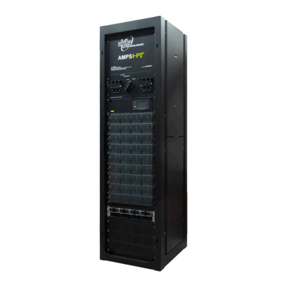
- Page 1 AMPS HP2 Power System Installation & Operation Manual Part #0260080-J0 Effective 09/2017 Your Power Solutions Partner member of The Group ™...
- Page 3 Canada and USA: 1-888-462-7487 International: +1-604-436-5547 Copyright Copyright © 2017 Alpha Technologies Ltd. All rights reserved. Alpha is a registered trademark of Alpha Tech- nologies. No part of this documentation shall be reproduced, stored in a retrieval system, translated, transcribed, or transmitted in any form or by any means manual, electric, electronic, electromechanical, chemical, optical, or otherwise without prior explicit written permission from Alpha Technologies.
-
Page 4: Table Of Contents
Table of Contents 1. Safety ������������������������������������������������������������������������������������������������������������������������������������6 1�1 Safety Symbols ������������������������������������������������������������������������������������������������������������������������������������6 1�2 General Warning and Cautions ������������������������������������������������������������������������������������������������������������6 1�3 General Safety �������������������������������������������������������������������������������������������������������������������������������������7 1�4 External Battery Safety ������������������������������������������������������������������������������������������������������������������������8 1�5 Utility Power Connection ����������������������������������������������������������������������������������������������������������������������8 1�6 Equipment Grounding ��������������������������������������������������������������������������������������������������������������������������9 2� Product Description�������������������������������������������������������������������������������������������������������������10 2.1 Power System Configuration Terminology �����������������������������������������������������������������������������������������10 2�2 Theory of Operation ���������������������������������������������������������������������������������������������������������������������������... - Page 5 6.2 L-ADIO �����������������������������������������������������������������������������������������������������������������������������������������������58 6.3 T2S Inverter Control Card ������������������������������������������������������������������������������������������������������������������60 6.4 Inverter Module Indicators �����������������������������������������������������������������������������������������������������������������61 6.5 Rectifier Features �������������������������������������������������������������������������������������������������������������������������������62 7� Commissioning the System ������������������������������������������������������������������������������������������������65 7.1 Tools Required �����������������������������������������������������������������������������������������������������������������������������������65 7.2 Commissioning the Inverter System ��������������������������������������������������������������������������������������������������67 8� System Maintenance ����������������������������������������������������������������������������������������������������������70 8.1 Preventative Maintenance �����������������������������������������������������������������������������������������������������������������70 8.2 Inverter and T2S Maintenance �����������������������������������������������������������������������������������������������������������72 8.3 Replacing an AIM2500 Inverter Module ���������������������������������������������������������������������������������������������75 8�4 Synchronizing the Maintenance Bypass ��������������������������������������������������������������������������������������������77 8.5 ...
- Page 6 List of Figures Figure 1 — Split Phase from a Single phase supply ��������������������������������������������������������������������������������10 Figure 2 — 2-Pole from a 3-phase supply ������������������������������������������������������������������������������������������������ 11 Figure 3 — Example wiring for AMPS inverter system w/ independent AC input feed for MBS ��������������� 12 Figure 4 — System Schematic with Generator and MBS �������������������������������������������������������������������������13 Figure 5 — AMPS HP2 Box Bay System ��������������������������������������������������������������������������������������������������14 Figure 6 ...
- Page 7 Figure 32 — AC and DC Connections ������������������������������������������������������������������������������������������������������53 Figure 33 — Bypass Aux Contacts AMPS HP2 3-30 ����������������������������������������������������������������������������������������������������������������������������54 Figure 35 — DC Connections, DC1 and DC2 �������������������������������������������������������������������������������������������54 Figure 34 — Bypass Aux Contacts AMPS HP2 1-10 and 2-20 �������������������������������������������������������������������������������������������������������������54 Figure 36 — Cordex CXC HP Controller (left side view) ��������������������������������������������������������������������������55 Figure 37 — LCD Color Touchscreen Display ������������������������������������������������������������������������������������������56 Figure 38 ...
-
Page 8: Safety
Keep it in a safe place. Re- view the drawings and illustrations contained in this manual before proceeding. If there are any questions regard- ing the safe installation or operation of this product, contact Alpha Technologies or the nearest Alpha representa- tive. -
Page 9: 1�3 General Safety
1.3 General Safety • Only qualified personnel shall install, operate, and service the power system and components. • Installation instructions provided with each unit. • Observe all applicable national and local electrical and building codes during installation. • Maintain the security of all SELV circuits in the system when connecting to other equipment like signaling/ alarm circuits, emergency power off (EPO) circuits, relay contacts, Ethernet or CANbus. -
Page 10: 1�4 External Battery Safety
• Remove all rings, watches and other jewelry before servicing batteries. • Recycle used batteries. Spent or damaged batteries are environmentally unsafe. Refer to local codes for the proper disposal of batteries. • A disconnect switch shall be provided by others for the AC input and AC output circuits. •... -
Page 11: 1�6 Equipment Grounding
WARNING! Multiple power inputs: disconnect all inputs before servicing to avoid electric shock. • AMPS-3-75 and AMPS-2-40 UPS are rated for use on a circuit capable of delivering no more than 10 KA rms symmetrical amperes, 120V maximum. • AMPS-3-30, AMPS2-20 and AMPS-1-10 UPS are rated for use on a circuit capable of delivering nor more than 5 KA rms symmetrical amperes, 120V maximum. -
Page 12: 2� Product Description
2. Product Description The Alpha Modular Power System (AMPS HP2) is a unique, high performance AC and hybrid AC/DC power system that is ideally suited to provide highly reliable back-up power to cable headend, telecom or server room facilities. The AMPS HP2 features hot swappable 2.5 kVA/2.0 kW inverter modules and optional 2.4 kW rectifier modules that are the building blocks of a highly reliable power system. -
Page 13: 2�2 Theory Of Operation
208V 208V 208V Figure 2 — 2-Pole from a 3-phase supply 120/208Vac 3-Phase Each phase conductor is 120 degrees out of phase with the other, as shown in Figure 2. All three phases (3-pole) plus the neutral are in use. 2.2 Theory of Operation Each AMPS module includes a reliable 48Vdc to 120Vac inverter as well as an AC-to-DC converter. -
Page 14: Figure 3 - Example Wiring For Amps Inverter System W/ Independent Ac Input Feed For Mbs
Boost Telecom Grade Mains AC Output 400 Vdc DC In Dual redundant communication and CAN bus external synchronization communication between modules AMPS modules also have a ‘Boost’ over-current feature with 10 times the rated current capacity for 20ms, allow- ing it to trip breakers downstream, thus protecting the load. 2.2.1 AC or DC input priority The user can choose either AC or DC input priority. -
Page 15: Figure 4 - System Schematic With Generator And Mbs
2.2.3 Wiring for Generator and/or External MBS Refer to Figure 4 for schematic of a system with a generator and/or external MBS. Figure 4 — System Schematic with Generator and MBS 0260080-J0 Rev D... -
Page 16: Figure 5 - Amps Hp2 Box Bay System
2.2.4 AMPS HP2 Models The versatile AMPS HP2 can be configured for use as an Inverter or a UPS in either single, split, or three-phase arrangements. 19-inch and 23-inch rack-mount versions are available in 10-30kVA inverter configurations. The seven-foot Box Bay, 40kVA & 75kVA are available as an Inverter or a UPS. All AMPS HP2 products use the same core modular inverter modules and are controlled by Alpha’s CXC HP controller. -
Page 17: Module Specifications
3. Module Specifications 3.1 Specifications for 48-120 Inverter Module General specifications: EMC (immunity): EN 61000-4 EMC (emission): EN55022 (Class A), FCC 47 VFR Part 15, class A Safety: IEC 60950, UL 1778 Issue 4 Cooling: Forced Air MTBF: 240000 hrs Efficiency (typical): Enhanced Power Conversion: On Line: AC Output Power Nominal: 2500 VA Resistive Load:... -
Page 18: Specifications For 48-2.4Kw Rectifier Module
3.2 Specifications for 48-2.4kW Rectifier Module Electrical Input Voltage: Nominal:208 to 277Vac Operating:187 to 310Vac Extended:90 to 187Vac (de-rated power) Input Frequency: 44 to 66Hz Power: 2400W continuous (1200W output @ 120Vac Input) Power Factor: >0.99 (50 to 100% load) THD: <5% Efficiency: 96.2% peak Output Voltage: 42 to 58Vdc (No load 46.5 to 58Vdc) Output Current: 44.5A @ 54Vdc (50A max.@ 48Vdc) (~25A @ 48Vdc at 120Vac Input) Load Regulation: <±0.7% (static) Line Regulation: <±0.1% (static) -
Page 19: 4� Amps Hp2: Box Bay Systems
4. AMPS HP2: Box Bay Systems The AMPS HP2 consists of a number of individual subsystems designed to work together to provide highly reli- able, filtered power in support of the load. A typical AMPS HP2 box bay system contains the following: 1. -
Page 20: Figure 8 - Amps Hp2, 40 Kva
1. Main Wiring Access Panel: AC input and output as well as Safety Extra-Low Voltage (SELV) DC battery connections are accessed through the front panel and fed through the knockouts at the top of the rack. 2. Inverter AC Input Breaker: Serves as the main disconnect for the inverter AC input. -
Page 21: Specifications Amps Hp2: Box Bay
4.1 Specifications AMPS HP2: Box Bay Model AMPS 3-75 (N+1) AMPS 3-75 AMPS 2-40 AMPS 2-40R (N+1) R AC Input Voltage 120/208Vac 120/208Vac 120/208Vac 2 Pole 120/208Vac 2 Pole 3-Phase 3-Phase (or) 120/240Vac (or) 120/240Vac Input Split-Phase Split-Phase Full Load inverter AC 190A 190A 160A... - Page 22 4.1.1 DC Fuse/Breaker AMPS HP2: Box Bay Alpha recommends using fuses instead of breakers because they provide better fault protection. NOTE: The recommendations in Table A are for reference only. A registered professional engineer must review and approve or modify these recommendations in compliance with applicable national and local electrical and building codes.
-
Page 23: System Pre-Installation
4.2 System Pre-Installation 4.2.1 Site Selection The AMPS HP systems are designed to be installed in a controlled environment, sheltered from rain, excessive dust and other contaminants. Consider both the floor loading and the physical space required for the power system and the batteries. 4.2.2 Floor Plan Layout Sufficient free space must be provided at the front and rear of the power system to meet the cooling requirements of the inverters and rectifiers(if installed) in the power system and to allow easy access to the power system com-... -
Page 24: Figure 9 - Installation Layout And Clearances
Figure 9 — Installation layout and clearances UNLESS OTHERWISE SPECIFIED THESE DESIGNS AND SPECIFICATIONS ARE DIM ARE IN INCHES CONFIDENTIAL, REMAIN THE PROPERTY OF 0.040 ALPHA TECHNOLOGIES LTD., AND SHALL NOT BE X.XX 0.020 COPIED OR USED WITHOUT ITS WRITTEN CONSENT X.XXX 0.010... -
Page 25: Figure 10 - Transporting The Cabinet
4.2.4 Transporting the Cabinet The cabinet is shipped upright on a 123 cm x 123 cm (48" x 48") pallet. The empty cabinet weighs approximately 320 kg (700 lb). The height of the rack, including pallet and shipping material is 232 cm (91.25"). When tilting the rack to fit through doors, tilt the rack toward the back and ensure that it is not subjected to sudden shock. - Page 26 4.2.5 Unpacking Instructions WARNING! The AMPS HP2 rack weighs 320 kg / 700 lb. Care must be taken to ensure that it does not topple over. 1. Loosen the four screws securing the upper side panel, and the four screws securing the lower side panel. 2.
-
Page 27: Figure 11 - Mounting Hole Pattern
4.2.6 Anchoring the Cabinet The cabinet must be fixed in place by means of anchor bolts. In areas prone to seismic events, use anchors rated for the appropriate Seismic zone. 18.94in 481mm 17.39in 442mm 15.85in 402mm 0.81in (TYP) 20.7mm Total dimensions, 22.00in 20.45in 18.91in... -
Page 28: 4�3 System Installation
4.3 System Installation The AMPS HP2 system is pre-configured from the factory for a single AC feed per phase for inverters, a mainte- nance bypass switch, and rectifiers if present. The installer is responsible for connecting the following: • Utility input to the system (120V line to neutral) •... -
Page 29: 4�4 Installation: Amps Hp2: Box Bay
4.4 Installation: AMPS HP2: Box Bay Carefully review the following schematic and installation notes before proceeding with the installation. Figure 12 — Battery and power connections Installation notes: 1. All wiring must be in accordance with applicable electrical codes. 2. All external wiring by others. 3. -
Page 30: Input/Output Cabling Overview
4.5 Input/Output Cabling Overview Connection points are accessed from the top of the unit. A protective panel partitions the AC and DC connections Protective panel between DC connections AC & DC connections (accessed via top cover) AC connections (accessed via front wiring cover) Figure 13 — Top view showing AC and DC connection partitions 0260080-J0 Rev D... -
Page 31: Figure 14 - Top View Showing Ac And Dc Connection
Frame Ground 1" knockout for rectifier Thermoplastic top cover AC feed (if equipped) for DC cabling (cut as required for pass through) 4 x 2" knockouts for Frame Ground* AC input and AC * Remove masking tape output to expose bare metal� Front cover wiring Removable side covers 1/2" knockout for MBS auxiliary contacts Figure 14 — Top view showing AC and DC connection 4.5.1 Wiring Gauge The required gauge of the AC input, DC+/DC- input and AC output cabling is determined by the current rat- ing, circuit breaker rating, typical ambient temperatures and the applicable local electrical codes. -
Page 32: 4�6 Ac Connections
4.6 AC Connections • Access to connection points is provided from the front of the system rack. • AC wires enter the cabinet through the top. • AC input and AC output wires are connected to box lugs rated for 350 kcmil to #6 AWG. •... -
Page 33: Figure 16 - Ac Connections
Rectifier AC Input Figure 16 — AC Connections (b) 0260080-J0 Rev D... -
Page 34: Figure 17 - Ac Connections Bypass Terminal Block
Bypass Terminal Block Open in Closed in Bypass Bypass Figure 17 — AC Connections Bypass terminal Block (c) 4.6.1 Bypass Terminal Block • The terminal bypass block is provided for customer convenience to monitor the position of the AMPS HP2 bypass switch. • There are two connection points •... -
Page 35: 4�7 Dc Connections
4.7 DC Connections • Access to connection points is provided through the opening in the top of the system rack • Access can also be provided by removing the side panels. Note that this will expose the installer to AC con- ductors and wiring. -
Page 36: Figure 18 - Top Feed System, Single Battery Feed
4.7.3 Top Feed Configured Systems (only) DC - Figure 18 — Top Feed System, Single Battery Feed Cable Tie Bar: For use between all cable landings (6 total) 0260080-J0 Rev D... -
Page 37: Figure 19 - Top Feed System, Dual Independent Battery Feeds
DC1 + DC2+ DC1 - DC2 - Figure 19 — Top Feed System, Dual Independent Battery Feeds Cable Tie Bar: For use between all cable landings (4 total) 0260080-J0 Rev D... -
Page 38: Figure 20 - Top Feed System, Four Independent Battery Feeds (No Tie Bars Required)
DC1 + DC2 + DC3 + DC4 + DC1- DC2 - DC3 - DC4 - Figure 20 — Top Feed System, Four Independent Battery Feeds (no tie bars required) 0260080-J0 Rev D... -
Page 39: Figure 21 - Bottom Feed System, Single Battery Feed
4.7.4 Bottom Feed Factory Configured Systems (only) DC - Figure 21 — Bottom Feed System, Single Battery Feed Cable Tie Bar: For use between all cable landings (6 total) 0260080-J0 Rev D... -
Page 40: Figure 22 - Bottom Feed System, Dual Independent Battery Feeds
DC2 - DC1 - DC2 + DC1 + Figure 22 — Bottom Feed System, Dual Independent Battery Feeds Cable Tie Bar: For use between all cable landings (4 total) 0260080-J0 Rev D... -
Page 41: Figure 23 - Bottom Feed System, Four Independent Battery Feeds (No Tie Bars Required)
DC3 - DC1 - DC2 - DC4 - DC1 + DC2 + DC3 + DC4 + Figure 23 — Bottom Feed System, Four Independent Battery Feeds (no tie bars required) 0260080-J0 Rev D... -
Page 42: Figure 24 - Single Battery Feed
4.7.5 Battery Feed Connections Battery cable lugs (3/8" diameter on 1" centers) Tie bars Figure 24 — Single Battery Feed Tie bars Figure 25 — Dual Independent Battery Feeds Figure 26 — Four Independent Battery Feeds (use with no tie bars) 0260080-J0 Rev D... -
Page 43: Amps Hp2: Rack Mount Systems
5. AMPS HP2: Rack Mount Systems The AMPS HP2 consists of a number of individual subsystems designed to work together to provide highly reli- able, filtered power in support of the load. A typical AMPS HP2 rack mount system contains the following: 1. -
Page 44: Specifications Amps Hp2: Rack Mount
5.1 Specifications AMPS HP2: Rack Mount Model AMPS-3-30 AMPS-2-20 AMPS-1-10 AC Input Voltage 120/208Vac 120/208Vac 2-Pole 120V Single Phase 3-Phase (or) 120/240Vac Split- Input Phase Full Load inverter AC Input Current (per phase) AC Input poles & wiring 4 w + G 3 w + G 2 w + G Wiring 3Φ Wye 2Φ... - Page 45 5.1.1 DC Fuse/Breaker AMPS HP2: Rack Mount Alpha recommends using fuses instead of breakers because they provide better fault protection. NOTE: The recommendations in Table B are for reference only. A registered professional engineer must review and approve or modify these recommendations in compliance with applicable national and local electrical and building codes.
-
Page 46: System Pre-Installation
5.2 System Pre-Installation 5.2.1 Site Selection The AMPS HP systems are designed to be installed in a controlled environment, sheltered from rain, excessive dust and other contaminants. Consider both the floor loading and the physical space required for the power system and the batteries. 5.2.2 Floor Plan Layout Sufficient free space must be provided at the front and rear of the power system to meet the cooling requirements of the inverters and rectifiers(if installed) in the power system and to allow easy access to the power system com-... -
Page 47: Figure 29 - Installation Layout And Clearances
THESE DESIGNS AND SPECIFICATIONS ARE DIM ARE IN INCHES Figure 29 — Installation layout and clearances CONFIDENTIAL, REMAIN THE PROPERTY OF 0.040 ALPHA TECHNOLOGIES LTD., AND SHALL NOT BE X.XX 0.020 COPIED OR USED WITHOUT ITS WRITTEN CONSEN X.XXX 0.010... - Page 48 5.2.4 Installing Into 23" Racks The AMPS HP2 Rack Mount system can be front mounted or mid mounted into a 23" rack using the adpater plates as shown in the following figures. Front Mount 30 KVA with 19 - 23" Adapter Plates FRONT MOUNT 30 KVA WITH ADAPTER PLATES 19"- 23"...
- Page 49 FRONT MOUNT 20 KVA WITH ADAPTER PLATES 19"- 23" Front Mount 20 KVA with 19 - 23" Adapter Plates 7X 1/2" TRS SCREWS FOR RACK INSTALL PER SIDE 2X 9 RU ADAPTER PLATE FRONT MOUNT 10 KVA WITH ADAPTER PLATES 5901456-009 19"- 23"...
- Page 50 Mid Mount 30 KVA with 19 - 23" Adapter Plates MID MOUNT 30 KVA WITH ADAPTER PLATES 19"- 23" 9X 1/2" TRS SCREWS FOR RACK INSTALL PER SIDE 2X 9 RU ADAPTER PLATE 5901456-009 4X 2 RU ADAPTER PLATE 5901456-002 9X 1/2"...
- Page 51 MID MOUNT 20 KVA WITH ADAPTER PLATES 19"- 23" Mid Mount 20 KVA with 19 - 23" Adapter Plates 7X 1/2" TRS SCREWS FOR RACK INSTALL PER SIDE 2X 9 RU ADAPTER PLATE 5901456-009 2X 2 RU ADAPTER PLATE MID MOUNT 10 KVA WITH ADAPTER PLATES 5901456-002 19"- 23"...
-
Page 52: 5�3 System Installation
5.3 System Installation The AMPS HP2 system is pre-configured from the factory for a single AC feed per phase for inverters, and a maintenance bypass switch. The installer is responsible for connecting the following: • Utility input to the system (120V line to neutral) •... -
Page 53: Installation: Amps Hp2: Rack Mount
5.4 Installation: AMPS HP2: Rack Mount Carefully review the following schematic and installation notes before proceeding with the installation. Figure 30 — Battery and power connections Installation notes: 1. All wiring must be in accordance with applicable electrical codes. 2. All external wiring by others. 3. -
Page 54: Figure 31 - Top View Showing Ac And Dc Connection
AC OUTPUT KNOCK OUT CHASSIS GROUND AC INPUT KNOCK OUT DC REAR ACCESS AC REAR ACCESS Figure 31 — Top view showing AC and DC connection 5.4.1 Wiring Gauge The required gauge of the AC input, DC+/DC- input and AC output cabling is determined by the current rating, circuit breaker rating, typical ambient temperatures and the applicable local electrical codes. -
Page 55: 5�5 Ac Connections
5.5 AC Connections DO NOT SCALE DRAWING • Access to connection points is provided from the front of the system rack. • AC wires enter the cabinet through the top. • AC input and AC output wires are connected to box lugs rated for 2/0 to #10AWG. AC IN DC2- DC1-... -
Page 56: 5�6 Dc Connections
THESE DESIGNS AND SPECIFICATIONS ARE DIM ARE IN INCHES CONFIDENTIAL, REMAIN THE PROPERTY OF DO NOT SCALE DRAWING 0.040 ALPHA TECHNOLOGIES LTD., AND SHALL NOT BE UNLESS OTHERWISE SPECIFIED X.XX 0.020 COPIED OR USED WITHOUT ITS WRITTEN CONSENT THESE DESIGNS AND SPECIFICATIONS ARE X.XXX... -
Page 57: 6� System Components
6. System Components 6.1 Cordex HP Controller The Cordex™ HP (CXC HP) controller provides centralized setup, control and monitoring of power systems. This ranges from simple monitoring and threshold alarms for temperature, voltage and current, to advanced battery charging and diagnostic features. The controller supports dual Ethernet ports and a 4.3”... -
Page 58: Figure 37 - Lcd Color Touchscreen Display
• USB: dual ports on both the front and rear of the controller for upgrades and file management via a standard USB flash drive. • CAN: dual independent CAN bus ports for communication with the Alpha Cordex™ and AMPS family of products, which allows for a greater number of devices. -
Page 59: Figure 38 - Inverter System Menus
6.1.1 Web Interface Features This section provides an overview of the Inverter system features via the controller's web interface. Refer to the Cordex HP Controller Software manual (0350058-J0) for more details. Inverter System Menus The Inverter system consists of menus to access inverter alarms, signals and settings. From the main dashboard go to Power System >... -
Page 60: L-Adio
6.2 L-ADIO The L-ADIO is the standard analog and digital I/O peripheral for low voltage (<60Vdc) systems. The L-ADIO com- municates on CAN bus to the controller and provides user access to I/O management via the CXC HP controller. 3 LED Status Indicators CAN Ports Power Input... - Page 61 6.2.4 LED Indication Each L-ADIO contains three LEDs for peripheral status indication. LVD – Yellow = LVD Override Engaged Power – Blue = Power present to device Comms – Green = L-ADIO has been acquired by CXC HP 6.2.5 Front Panel Reset Button A reset button is located on the front panel.
-
Page 62: T2S Inverter Control Card
6.3 T2S Inverter Control Card The CXC HP unified system controller monitors and manages inverter modules by communicating with the T2S inverter control card. The T2S may be useful in troubleshooting inverter alarms. LEDs 1 through 3 on the front panel of the T2S indicate the following alarm conditions: •... -
Page 63: Inverter Module Indicators
6.4 Inverter Module Indicators AC output DC input AC input Output power Status LEDs indicator LEDs Figure 41 — Fig. 4.1 Inverter module status, power LEDs 6.4.1 Status LEDs Inverter Status LED Description Remedial action No input power or forced stop Check AC input Permanent green AC Input OK, normal operation None required Flashing green Inverter OK but conditions are not ... -
Page 64: Rectifier Features
6.5 Rectifier Features 6.5.1 Front Panel LEDs The front panel LEDs indicate the rectifier status summary and patterned response to Locate Module command. Refer to the Cordex CXRF 48-2.4 kW manual for further details. LEDs 1 2 3 Figure 43 — Rectifier front panel LEDs ALARM / FAULT (1) The red LED is on during an active Module Fail alarm if the module is unable to source power due to a fault con- dition. - Page 65 6.5.2 Rectifier Rear Panel Refer to the Cordex CXRF 48-2.4 kW manual for shelf power and communications connections details. 6.5.3 True Module Fail Alarm The power modules have a “true” fail alarm that provides a true indication of the power module’s ability to source current.
-
Page 66: Figure 44 - Locking Handle Disengaged/Engaged
6.5.9 Start Delay The rectifier modules are equipped with a delay timer to stagger-start a series of modules. When multiple mod- ules and multiple shelves, part of a larger system are used in conjunction with a controller, a start delay prevents all rectifiers from starting at the same time and causing an inrush on the utility. -
Page 67: 7� Commissioning The System
7. Commissioning the System 7.1 Tools Required The following tools are required to commission the AMPS HP system for the first time: • Medium flat screwdriver with approximately 3/8" (5 mm) blade width • True RMS digital multimeter • Computer with Ethernet connection and Internet Explorer (9+), Chrome Safari or Firefox •... -
Page 68: Figure 45 - Inverter Module Showing Ac Input Led
AC input LED Figure 45 — Inverter module showing AC input LED Starting-up the system 12. Switch on the AC mains/utility power. 13. Verify the AMPS HP system AC input voltages at the AC wiring terminals. System Voltage Value Neutral to Earth Ground System Voltage Value 3 phase L1 to L2, L2 to L3, L3 to L1... -
Page 69: Commissioning The Inverter System
7.2 Commissioning the Inverter System Once a system has been created, and a T2S is assigned to the system, it can be commissioned. There are three stages to commissioning an inverter system: 1. Setting system options 2. Commissioning seed inverters 3. - Page 70 7.2.2 Commission Seed Inverters The second stage of commissioning involves inserting one seed inverter for each phase. The seed inverter provides a reference for all other inverters in the same phase so they can learn their power configuration and the phase shift.
- Page 71 7.2.4 Mapping Alarms to Relays 1. Connect a computer to the controller. Refer to the controller software manual. The 48Vdc power must be switched on before the controller can operate. Provide either DC power on the main DC1 connections or switch on at least one rectifier.
-
Page 72: 8� System Maintenance
8.1 Preventative Maintenance This equipment requires regular maintenance. The maintenance must be done by qualified service personnel only. Contact Alpha Technologies at 1-888-462-7487 for any assistance with maintenance. WARNING! WARNING: HIGH VOLTAGE AND SHOCK HAZARD Use extreme care when working inside the enclosure/shelf while the system is energized. - Page 73 Table C — Tools 9/16" ratchet socket 9/16" ratchet socket extended neck 5/8" ratchet socket 5/8" ratchet socket extended neck 10 mm combo wrench 10 mm flat gear ratchet 3/8" Allen key on a 3/8" ratchet socket 3/16" Allen key on a 3/8" ratchet socket Flash light or trouble light Crossover Ethernet cable Straight through Ethernet cable Computer with Ethernet port and Firefox or Chrome True RMS digital multimeter Other Recommended Tools Service /Maintenance Commissioning Needle nose pliers Side cutters Wire stripper 10 AWG to 20 AWG...
-
Page 74: Inverter And T2S Maintenance
8.2 Inverter and T2S Maintenance This section covers inverter and T2S maintenance including: replacing, identifying, alarms and alerts, DC priority and AC input power limit. 8.2.1 Changing the System Configuration Once the system has been created, most of the system configuration cannot be changed. The number phases, number of DC groups and number of shelves per phase cannot be changed. - Page 75 8.2.3 Taking Power from DC Source The inverter system can take power from the DC source (usually batteries) under three conditions: 1. AC mains is lost; 2. Manual DC Priority is enabled; 3. AC Input power limit is enabled. When AC mains is lost, the inverters will always take power from the DC source if available. Using Manual DC Priority It is possible to manually instruct the inverters to take some amount power from DC.
- Page 76 8.2.6 Identifying an Inverter If an inverter is in alert it is usually necessary to identify and locate the inverter in the rack. There are two ways to do this: 1. Go to Power System > Inverter System > Inventory > Inverters > Status. This view shows all inverters within the system in a table view.
-
Page 77: Replacing An Aim2500 Inverter Module
8.3 Replacing an AIM2500 Inverter Module 8.3.1 Replacing Inverters Follow these step to replace one or more inverters: 1. Go to Power system > Inverter System > Inventory > Inverters > Status. 2. Pull out the inverters that must be replaced. The information on the Status page will help identify inverters in alert. -
Page 78: Figure 48 - Unlocking And Locking An Inverter Module For Removal Or Insertion
A new module can take between 5 and 10 minutes to synchronize with the T2S controller and clear any alarms. Do not interact with the system during the AC output initialization process. DC input When the initialization sequence is complete, the AC input three LEDs on the left hand side of the inverter mod- ule turn a solid green. -
Page 79: 8�4 Synchronizing The Maintenance Bypass
8.4 Synchronizing the Maintenance Bypass For system configurations that use a generator for the AC input, the safest way to initiate a maintenance bypass is to follow the instructions in the Initiate Zero Phase Shift wizard. This wizard should be used whenever the inverter system has to be put into or taken out of bypass. This prevents the inverters from turning off when the bypass switch briefly short-circuits the AC input and output. -
Page 80: Fuse Replacement (Box Bay)
8.5 Fuse Replacement (Box Bay) These fuses are sized to blow only if there is a short on the bypass line. These fuses must be replaced by a quali- fied service person. 1. Put critical loads on External Bypass, refer to 8.4.1. WARNING! There may still be live parts inside the system and shock hazards may be present throughout this procedure. -
Page 81: Tvss Replacement (Box Bay)
8.6 TVSS Replacement (Box Bay) Make sure the spare parts are available on site. WARNING! There may still be live parts inside the system and shock hazards may be present throughout this procedure. Replaceable parts Alpha part number Description 162-602-19 Strikesorb 40 TVSS protection module WARNING! To prevent electrical hazards such as short circuits, ensure that the system is free of... -
Page 82: Fuse Replacement (Rack Mount)
8.7 Fuse Replacement (Rack Mount) 1. Put system into external bypass and remove all AC and DC from the AMPS HP2 system, refer to 8.4.1. 2. Remove the AC cover with a Phillips head screw driver. 3. Remove the fuse using a 7/16 hex nut screwdriver. 4. -
Page 83: Tvss Replacement (Rack Mount)
8.8 TVSS Replacement (Rack Mount) 1. Put system into external bypass and remove all AC and DC from the AMPS HP2 system, refer to 8.4.1. 2. Pull out the surge suppression module. 3. Replace the module with one of the same type and rating. Replaceable parts Alpha part number Description... -
Page 84: Replacing The T2S Inverter Control Card
8.9 Replacing the T2S Inverter Control Card Replacing the T2S Inverter Control Card, use PN 0180072-001. CAUTION! Perform this procedure with the system in bypass mode and/or during a scheduled maintenance window. Step 1: Removal To release the T2S from the shelf, insert a small flat screwdriver in the square hole under the USB port and lift up the lock pin. -
Page 85: 9� Troubleshooting
9. Troubleshooting 9.1 Incorrect System Configuration If the system has been incorrectly configured with the wrong number of phases, the commissioning wizard will need to be executed again. If the number of DC Groups is incorrect, it is likely that some inverters have the incorrect DC group number. It is possible to fix this by manually changing the DC group number in the details screen of each inverter. - Page 86 minder to check the T2S log file. It is recommended to download and view the log file for any possible problems. Downloading the log file will also clear the alarm. To check the T2S log file: 1. Determine which T2S is the source of the alarm. Go to Power System > Inverter System> Live Alerts and look for the Check Log File alarm in the list.
-
Page 87: 10� Warranty
10. Warranty Technical Support In Canada and the USA, call toll free 1-888-462-7487. Customers outside Canada and the USA, call +1-604-436-5547. Warranty Statement For full information details review Alpha's online Warranty Statement at www.alpha.ca/support. Product Warranty Alpha warrants that for a period of two (2) years from the date of shipment its products shall be free from defects under normal authorized use consistent with the product specifications and Alpha’s instructions, the terms of the manual will take precedence. -
Page 88: Certification
11. Certification About CSA and NRTL CSA (Canadian Standards Association also known as CSA International) was estab- lished in 1919 as an independent testing laboratory in Canada. CSA received its rec- ognition as an NRTL (Nationally Recognized Testing Laboratory) in 1992 from OSHA (Occupational Safety and Health Administration) in the United States of America (Docket No. - Page 92 Canada and USA: 1-888-462-7487 International: +1-604-436-5547 Visit us at www.alpha.ca Due to continuing product development, Alpha Technologies reserves the right to change specifications without notice. Copyright © 2017 Alpha Technologies. All Rights Reserved. Alpha® is a registered trademark of Alpha Technologies.
Need help?
Do you have a question about the AMPS HP2 Power System and is the answer not in the manual?
Questions and answers