Sign In
Upload
Manuals
Brands
Alpha Technologies Manuals
Inverter
AMPS HP2 Power System
Alpha Technologies AMPS HP2 Power System Manuals
Manuals and User Guides for Alpha Technologies AMPS HP2 Power System. We have
1
Alpha Technologies AMPS HP2 Power System manual available for free PDF download: Installation & Operation Manual
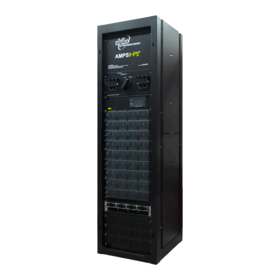
Alpha Technologies AMPS HP2 Power System Installation & Operation Manual (92 pages)
Brand:
Alpha Technologies
| Category:
Inverter
| Size: 16 MB
Table of Contents
Table of Contents
4
Safety
8
1�1 Safety Symbols
8
1�2 General Warning and Cautions
8
1�3 General Safety
9
1�4 External Battery Safety
10
1�5 Utility Power Connection
10
1�6 Equipment Grounding
11
2� Product Description
12
Power System Configuration Terminology
12
Figure 1 - Split Phase from a Single Phase Supply
12
2�2 Theory of Operation
13
Figure 2 - 2-Pole from a 3-Phase Supply
13
Figure 3 - Example Wiring for AMPS Inverter System W/ Independent AC Input Feed for MBS
14
Figure 4 - System Schematic with Generator and MBS
15
Figure 5 - AMPS HP2 Box Bay System
16
Figure 6 - AMPS HP2 Rack Mount System
16
Module Specifications
17
Specifications for 48-120 Inverter Module
17
Specifications for 48-2.4Kw Rectifier Module
18
4� AMPS HP2: Box Bay Systems
19
Figure 7 - AMPS HP2, 3-75
19
Figure 8 - AMPS HP2, 40 KVA
20
Specifications AMPS HP2: Box Bay
21
System Pre-Installation
23
Figure 9 - Installation Layout and Clearances
24
Figure 10 - Transporting the Cabinet
25
Figure 11 - Mounting Hole Pattern
27
4�3 System Installation
28
4�4 Installation: AMPS HP2: Box Bay
29
Figure 12 - Battery and Power Connections
29
Figure 13 - Top View Showing AC and DC Connection Partitions
30
Input/Output Cabling Overview
30
Figure 14 - Top View Showing AC and DC Connection
31
4�6 AC Connections
32
Figure 15 - AC Connections
32
Figure 16 - AC Connections
33
Figure 17 - AC Connections Bypass Terminal Block
34
4�7 DC Connections
35
Figure 18 - Top Feed System, Single Battery Feed
36
Figure 19 - Top Feed System, Dual Independent Battery Feeds
37
Figure 20 - Top Feed System, Four Independent Battery Feeds (no Tie Bars Required)
38
Figure 21 - Bottom Feed System, Single Battery Feed
39
Figure 22 - Bottom Feed System, Dual Independent Battery Feeds
40
Figure 23 - Bottom Feed System, Four Independent Battery Feeds (no Tie Bars Required)
41
Figure 24 - Single Battery Feed
42
Figure 25 - Dual Independent Battery Feeds
42
Figure 26 - Four Independent Battery Feeds (Use with no Tie Bars)
42
AMPS HP2: Rack Mount Systems
43
Figure 27 - AMPS HP2 Rack Mount, Back View
43
Figure 28 - AMPS HP2 Rack Mount, Front View
43
Specifications AMPS HP2: Rack Mount
44
System Pre-Installation
46
Figure 29 - Installation Layout and Clearances
47
5�3 System Installation
52
Figure 30 - Battery and Power Connections
53
Installation: AMPS HP2: Rack Mount
53
Figure 31 - Top View Showing AC and DC Connection
54
5�5 AC Connections
55
Figure 32 - AC and DC Connections
55
5�6 DC Connections
56
Figure 33 - Bypass Aux Contacts
56
Figure 34 - Bypass Aux Contacts
56
Figure 35 - DC Connections, DC1 and DC2
56
6� System Components
57
6�1 Cordex HP Controller
57
Figure 36 - Cordex CXC HP Controller (Left Side View)
57
Figure 37 - LCD Color Touchscreen Display
58
Figure 38 - Inverter System Menus
59
L-Adio
60
Figure 39 - L-ADIO I/O Peripheral
60
T2S Inverter Control Card
62
Figure 40 - T2S Front Panel
62
Inverter Module Indicators
63
Figure 41 - Fig. 4.1 Inverter Module Status, Power Leds
63
Figure 42 - Output Power Indicator Leds
63
Rectifier Features
64
Figure 43 - Rectifier Front Panel Leds
64
Figure 44 - Locking Handle Disengaged/Engaged
66
7� Commissioning the System
67
Tools Required
67
Figure 45 - Inverter Module Showing AC Input LED
68
Commissioning the Inverter System
69
Figure 46 - Commission Inverter System Wizard
69
8� System Maintenance
72
Preventative Maintenance
72
Inverter and T2S Maintenance
74
Figure 47 - Add/Remove Inverters
74
Replacing an AIM2500 Inverter Module
77
Figure 48 - Unlocking and Locking an Inverter Module for Removal or Insertion
78
Figure 49 - Inserting and Removing an Inverter Module
78
8�4 Synchronizing the Maintenance Bypass
79
Fuse Replacement (Box Bay)
80
Figure 50 - MBS Fuse Locations
80
TVSS Replacement (Box Bay)
81
Figure 51 - TVSS Protection Modules
81
Fuse Replacement (Rack Mount)
82
TVSS Replacement (Rack Mount)
83
Replacing the T2S Inverter Control Card
84
Figure 52 - T2S LED Sequence During Initialization
84
9� Troubleshooting
85
Incorrect System Configuration
85
Wrong Inverter AC Input Group
85
Wrong Inverter DC Input Group
85
9�4 T2S Expert Operations
85
9�5 Troubleshooting and Clearing System Error Alarm
85
10� Warranty
87
Certification
88
Advertisement
Advertisement
Related Products
Alpha Technologies ALPHA OUTBACK ENERGY Cordex HP LPS04
Alpha Technologies ALPHA OUTBACK ENERGY Cordex HP LPS36 Compact
Alpha Technologies INVERTER 2000
Alpha Technologies Categories
UPS
Power Supply
Intercom System
Media Converter
Industrial Equipment
More Alpha Technologies Manuals
Login
Sign In
OR
Sign in with Facebook
Sign in with Google
Upload manual
Upload from disk
Upload from URL